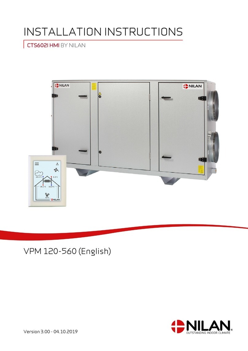
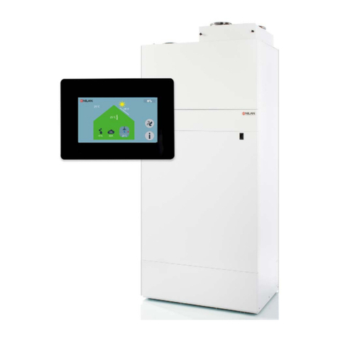
nilan Compact S CTS 602 User manual

INSTALLATION INSTRUCTIONS
CTS602 BY NILAN
Comfort 200 Top (English)
Version 2.10 - 22.08.2017

TABLE OF CONTENTS
Safety
Power supply................................................................................................................................................................................................................................................................... 4
Disposal............................................................................................................................................................................................................................................................................................. 4
Ventilation system....................................................................................................................................................................................................................................................4
General information
Introduction.................................................................................................................................................................................................................................................................................. 5
General information prior to installation.........................................................................................................................................................................................5
Final inspection......................................................................................................................................................................................................................................................................... 5
Ventilation ........................................................................................................................................................................................................................................................................ 5
Unit type........................................................................................................................................................................................................................................................................................... 6
Product description..................................................................................................................................................................................................................................................6
Dimensional drawing left model.................................................................................................................................................................................................................7
Dimensional drawing right model.............................................................................................................................................................................................................8
Accessories................................................................................................................................................................................................................................................................................... 9
Electrical preheating element for frost protection.............................................................................................................................................................. 9
Adjustable water comfort heater............................................................................................................................................................................................................ 9
Electric heating element.....................................................................................................................................................................................................................................9
EM box ....................................................................................................................................................................................................................................................................................9
DBTU damper.................................................................................................................................................................................................................................................................. 9
Pollen filter F7............................................................................................................................................................................................................................................................ 10
Water trap....................................................................................................................................................................................................................................................................... 10
Vibration absorbers.............................................................................................................................................................................................................................................10
Flexible silencing...................................................................................................................................................................................................................................................... 10
CO2 sensor..................................................................................................................................................................................................................................................................... 10
Installation
Mounted........................................................................................................................................................................................................................................................................................ 11
Placement of the unit ........................................................................................................................................................................................................................................ 11
Top unit ............................................................................................................................................................................................................................................................................. 11
Electrical
Electrical Installation...................................................................................................................................................................................................................................................... 12
Safety.................................................................................................................................................................................................................................................................................. 12
Electrical connections........................................................................................................................................................................................................................................12
Control panel............................................................................................................................................................................................................................................................................13
CTS602 control panel......................................................................................................................................................................................................................................... 13
Control panel connection............................................................................................................................................................................................................................... 13
Electrical connection, unit.........................................................................................................................................................................................................................................14
Supply.................................................................................................................................................................................................................................................................................. 14
Unit..........................................................................................................................................................................................................................................................................................14
Electrical connections accessories................................................................................................................................................................................................................. 15
Connection to user option and modbus ........................................................................................................................................................................................ 15
External electrical preheating element ........................................................................................................................................................................................ 16
Electrical comfort heater...............................................................................................................................................................................................................................17
Water comfort heater .......................................................................................................................................................................................................................................18
Plumbing
Condensation drain...........................................................................................................................................................................................................................................................20
Important information .....................................................................................................................................................................................................................................20
Connection bottom............................................................................................................................................................................................................................................... 21
Plumbing connections for accessories........................................................................................................................................................................................................22
Water lock with ball (option)....................................................................................................................................................................................................................... 22
Hot water heater (accessory) .................................................................................................................................................................................................................. 23
2

Ventilation installation
Ducts................................................................................................................................................................................................................................................................................................. 25
Legislation...................................................................................................................................................................................................................................................................... 25
Ducts..................................................................................................................................................................................................................................................................................... 25
Unit..........................................................................................................................................................................................................................................................................................25
Extract air........................................................................................................................................................................................................................................................................26
Supply air......................................................................................................................................................................................................................................................................... 26
Roof stack....................................................................................................................................................................................................................................................................... 26
Installation example.............................................................................................................................................................................................................................................27
Regulation................................................................................................................................................................................................................................................................................... 27
Important information...................................................................................................................................................................................................................................... 27
Software settings
Control panel............................................................................................................................................................................................................................................................................28
Functions..........................................................................................................................................................................................................................................................................28
Service menu............................................................................................................................................................................................................................................................... 29
Heating element ......................................................................................................................................................................................................................................................30
Air quality........................................................................................................................................................................................................................................................................ 31
Air changes.................................................................................................................................................................................................................................................................... 32
Defroster ........................................................................................................................................................................................................................................................................ 33
Temp. control ............................................................................................................................................................................................................................................................. 34
Room control................................................................................................................................................................................................................................................................35
Re-start ............................................................................................................................................................................................................................................................................ 36
Reset..................................................................................................................................................................................................................................................................................... 37
Manual.................................................................................................................................................................................................................................................................................38
PWR save .........................................................................................................................................................................................................................................................................39
Modbus............................................................................................................................................................................................................................................................................... 40
Datalog .............................................................................................................................................................................................................................................................................. 41
User select .....................................................................................................................................................................................................................................................................42
User select 2 ................................................................................................................................................................................................................................................................43
Alarm list.......................................................................................................................................................................................................................................................................... 44
Comfort 200 Top (English) BY NILAN
3

Safety
Power supply
CAUTION
Always disconnect mains electricity to the unit if a fault occurs which cannot be rectified via the
control panel.
CAUTION
If a fault occurs on the electricity-conducting elements of the unit, always contact an
authorised electrical installer to rectify the fault.
CAUTION
Always disconnect mains electricity to the unit before opening the doors, e.g. for installation,
inspection, cleaning and filter change.
Disposal
Ventilation system
Nilan units mainly consist of recyclable materials. They should therefore not be
disposed of with household refuse. Take them to your local recycling centre.
4

General information
Introduction
General information prior to installation
The following documents are supplied with the unit:
• Installation instructions/Software instructions
• User manual
• Wiring diagram
The instructions can be downloaded from the Nilan website: http://www.nilan.dk/da-dk/forside/
download
If you have further questions on unit installation after reading the instructions, contact your nearest
Nilan distributor, who can be found on www.nilan.dk/forhandlere.
The purpose of these instructions is to give the installer advice on correct installation and maintenance
of the unit.
The unit must be started up immediately after installation and connection to the duct system. In
periods where the ventilation system is not in operation, humid air from the rooms may penetrate into
the ducts and form a condensate. The condensate may leak out of the valves and damage furniture and
floors. In addition, condensate may form inside the unit, damaging the unit's electronics and fans.
The unit is supplied fully tested and ready for operation.
Final inspection
Ventilation
How to set the ventilation
This list is made to give the installer an overview of the settings, which he has to make by consulting
the user or builder
Function Settings
Setting the filter change period outdoor air Days:
Setting the filter change period extract air Days:
Which ventilation level is set for basic ventilation Level:
Is low ventilation at low outdoor temperature wanted yes/no Level:
At °C:
Is low ventilation at low humidity wanted yes/no Level:
Is high ventilation at high humidity wanted yes/no Level:
Setting for maximum time high humidity Min:
What is the wanted room temperature °C:
Master sensor for room temperature T3/TExt
Is high ventilation in cooling mode wanted yes/no Level:
Is a cooker-hood connected to the ventilation system yes/no Level:
Is the preheating-element activated (Polar version) yes/no
Comfort 200 Top (English) BY NILAN
5

Unit type
Product description
Comfort 200 Top is a ventilation unit with heat recovery. The unit is designed for air flows up to 308
m3/h at 100 Pa external duct pressure.
The unit draws the humid, vitiated air out of the dwelling via the bathroom, WC, kitchen and utility room
and introduces fresh outdoor air into habitable rooms such as living room, bedrooms and office. The
cold outdoor air is heated up in the heat exchanger by the warm exhaust air.
Comfort 200 Top is supplied as standard with a G4 filter in the outdoor air and extract air ducts. If it is
wished to filter the outdoor air for pollen, an F7 filter can be purchased as an accessory and mounted
subsequent.
1. Duct connections
2. Electrical connections
3. Automatic control system
4. Bypass-damper
5. Extract air filter G4 (left model)
6. Outdoor air filter G4 (F7 filter is fitted here) (left model)
7. Supply air fan (inlet air)
8. Extract air fan (outlet air)
9. Counterflow heat exchanger
10. Condensate drain
6

Dimensional drawing left model
All dimensions are in mm.
600
650
424
Ø 125
105
106
301
105
3 1
2 4
600
5 195
Connections:
1. Outdoor air
2. Supply air
3. Extract air
4. Discharge air
5. Condensate drain
Comfort 200 Top (English) BY NILAN
7

Dimensional drawing right model
All dimensions are in mm.
1 3
600
650
Ø 125
105
106
301
105
4 2
424
600
5 195
Connections:
1. Outdoor air
2. Supply air
3. Extract air
4. Discharge air
5. Condensate drain
8

Accessories
Electrical preheating element for frost protection
In longer periods of sub-zero temperatures, the high-efficiency counterflow heat
exchanger will ice up. To avoid icing, it is recommended that an electrical
preheating element is mounted.
The preheating element uses very little energy, but ensures efficient heat
recovery without de-icing, thus achieving an overall saving in energy
consumption.
Adjustable water comfort heater
A water comfort heater can be used to increase supply air temperature to the
desired level. It is fitted in the supply air duct and must be connected to the
primary heat supply.
Supplied with a two-way regulating valve, temperature sensor and frost
thermostat.
Electric heating element
An electric heating element allows the supply air temperature to be raised to the
desired level. Electric heating elements are supplied for mounting in the supply
air duct, and are provided with the necessary sensors.
EM box
With an EM box it is possible to divide the extract air between the kitchen and
bathroom.
If the cooker hood is operating via the unit and is switched on, air extraction from
the bathroom reduces slightly to allow sufficient air for the cooker hood to
extract kitchen fumes.
The EM box has a metal filter which efficiently separates grease particles from
the cooker hood air, thus protecting the unit.
DBTU damper
If there is not enough space to fit an EM-box, Nilan offers a DTBU damper, which
can be fitted between kitchen and bathroom. The damper functions precisely like
the EM-box but requires longer cables.
Comfort 200 Top (English) BY NILAN
9

Pollen filter F7
The unit is supplied as standard with a G4 filter.
If persons in the dwelling suffer from a pollen allergy, there is an option for
mounting a F7 pollen filter in the outdoor air inlet to minimise the pollen in the
indoor air.
Water trap
To ensure that the condensate can drain off freely, a water trap must be
established.
The water trap must be regularly checked for water. In the summer season,
where no condensation will occur, there is a risk of the water trap drying out. The
Nilan water trap contains a ball which cease to prevent "false" air intake into the
unit, so that condensate can run freely out of the unit.
Vibration absorbers
4 pc. of vibration absorbers are placed under the unit and secure an effective
dimming of the vibrations of the unit againt the surface.
Flexible silencing
To facilitate later servicing of the unit, we recommend fitting a flexible
connection between the unit and the duct system.
Nilan's sound damping flexi-hose gives good sound damping both to the duct
system and to roof stacks.
CO2sensor
Fitting a CO2sensor means the ventilation speed can be pre-programmed to run
higher ventilation levels in the event of high CO2level in the extracted air. CO2
levels can be programmed.
Installation of the CO2sensor must ordered from the factory.
10

Installation
Mounted
Placement of the unit
ATTENTION
When fitting the unit you should always take future service and maintenance in consideration.
It must be easy to replace the filters and ef it must be possible to take out the heat exchanger,
fan or other components.
ATTENTION
A minimum distance of 60 cm in front of the unit is recommended for workspace.
ATTENTION
The unit must be installed level for the sake of the condensate drain.
The unit is low-noise and low-vibration. However potential vibrations spreading from the unit to the
individual building parts must be taken into account. To detach the system from the floor, we
recommend that the system is placed on vibration absorbers. To other building parts and other fixtures
there should be a distance of about 10 mm.
The unit can be installed both inside and outside the building envelope because it is isolated and meets
the requirements for heat loss.
Top unit
Min. 20 cm
Min. 50 cm
Min. 60 cm
Service area in front of the unit
ATTENTION
If a cover is used to protect the unit, this must be easy to remove.
Comfort 200 Top (English) BY NILAN
11

Electrical
Electrical Installation
Safety
ATTENTION
All work must be carried out by qualified personnel and in accordance with applicable legislation
and regulations.
ATTENTION
It is important that power is disconnected when working with the unit's electrical components.
It is important to check that cables have not been damaged or trapped during connection and use.
Electrical connections
All connection points are on the top of the unit
1. Connecting 230V (remember earth wire)
2. Control panel connection
3. Connecting PC via a USB AB kabel
4. Connection through bushing to external connections
12

Control panel
CTS602 control panel
The control panel is supplied as standard with 1.5 m of cable. The panel is connected to the CTS602
control panel on the unit using twisted pair cable type 2x2x0.25 mm2(max. length 50 m).
The CTS602 panel should be located in a dry place protected from frost. Position panel 1.5 m above the
floor and min. 0.5 m from any corner. Wherever possible, avoid installing the panel on an outer wall, as
cold seepage can affect the panel sensor. Installation in areas with strong sunlight should also be
avoided.
Control panel connection
Comfort 200 Top (English) BY NILAN
13

Electrical connection, unit
Supply
CAUTION
Power sypply including safety switch must be installed by a certified electrician.
It comes with a power cable for connection in socket. It is important for the unit to be bonded to
earth.
Unit
Power supply
Safety switch
14

Electrical connections accessories
Connection to user option and modbus
User option: Connection to the user option can be used for e.g. controlling an extractor damper motor
via a potential-free contact. Connection is made in pins 4 and 5 in the control panel's 8 pole connector.
The user option can also be used for other functions, e.g. to create imbalance in supply and extraction
ventilation.
Modbus : It is possible to communicate with the unit via modbus, which can be connected in pins 6 and 7
in the control panel's 8 pole connector.
Please refer to the user guide for setting up software etc.
Connect the plug to the unit at point 2: Control panel connection.
CTS/Computer
Converter
Modbus
Comfort 200 Top (English) BY NILAN
15

External electrical preheating element
If the unit is the non-Polar version, an external preheating element can be purchased for retro-fitting.
The electric preheating element is mounted in the outdoor air duct before the unit with the necessary
temperature sensor.
1x230V ~ 50 Hz max. 16A
7 8
Min. 25 cm
T
It is important that the sensor is placed at least 25 cm from the preheating element to achieve correct
regulation.
The preheating element is fitted with a three-step safety system to prevent
overheating.
1. A thermostat regulates heat and ensures that the supply air temperature does
not go below -1 °C
2. A max. thermostat switches off the preheating element if the temperature
exceeds 50 °C
3. A manual safety thermostat can be used to switch off the preheating element
if the temperature exceeds 100 °C
ATTENTION
When mounting the electric preheating element, there must be a safety gap of minimum 15 cm
from any flammable material. The heating element must be insulated with a fire retardant
insulation material, but the cover on the connection box must not be insulated.
Dimensional drawing:
Ø125
Positioning options:
16

Electrical comfort heater
For precision control of supply air temperature, a comfort heater is required.
A comfort heater can be bought for installation in the supply duct (intake). The sensor and connection
to the control unit are supplied
0-10V
GND
1x230V ~ 50 Hz max. 16A
Min. 50 cm Min. 25 cm
T7
0-10V
GND
T7
Wiring diagrams are included with the products.
Cables are run along the duct and through bushings on the top of the unit down to the PCB, where they
are connected according to the wiring diagram.
ATTENTION
When fitting a comfort heater, ensure a safety gap of minimum 15 cm to any flammable
material. Insulate the comfort heater with a fire-resistant insulation material. Do not insulate
the connection box lid.
Dimensional drawing:
Ø125
Positioning options:
Comfort 200 Top (English) BY NILAN
17

Water comfort heater
For precision control of supply air temperature, a comfort heater is required.
A water heating element can be bought for installation in the supply duct (intake). The sensor and
connection to the control unit are supplied.
Connecting sensors
B3
T7
T9
Min. 50 cm
T9
B3
T7
T7: Temperature sensor - T9: Temperature sensor, comfort heater - B3: Frost protection
Cables are run along the duct and through bushings down to the PCB, where they are connected
according to the wiring diagram.
18

Electrical connection of two-way valve
N
L1
0-10V
GND
Cables are run along the duct and through bushings down to the PCB, where they are connected
according to the wiring diagram.
Dimensional drawing:
83
310
440
Ø 160
238
22
32
31
300
3/4" RG
3/4" RG
Comfort 200 Top (English) BY NILAN
19

Plumbing
Condensation drain
Important information
The unit is supplied with dia. 20 mm condensate drain (PVC, GF-fittings).
ATTENTION
Awater trap must be established in the condensate drain in order to ensure that condensate
can drain off.
ATTENTION
If the unit is assembled outside the climate screen, it is important to secure the condensate
drain against icing with a heating cable. Frost protection of the unit is the installer's
responsibility.
During operation, a underpressure of up to 500 Pa may develop in the drain, corresponding to
50 mm water column. This water trap must therefore be mounted as shown in order to prevent
drying out and return flow.
The connection of the water trap must be air-tight, otherwise air will be let into the unit and
condensate will remain in the unit. This could lead to water damage if the condensate overflows
the condensate tray and from there out of the unit.
After mounting the water trap, its function is tested as follows (the unit must be connected to
the duct system and the lid must be closed).
The condensation tray are filled with water and the unit is operated at the highest fan speed.
Allow it to run for several minutes. Check that there is no water in the condensation tray when
the test is finished.
The water trap may dry out and thus prevent water escaping from the condensate tray, as air
will be sucked into the unit. The water trap should therefore be checked at regular intervals,
especially in the summer, and filled with water as necessary. Increasing the height of the water
trap compared to the minimum requirements will minimize the need tor refilling.
INFO
Nilan offers a water trap with a ball. The ball ensures that no air is sucked into the unit through
the condensate drain if the water trap dries out. This ensures that water in the condensate tray
can drain off and it makes it unnecessary to check the condensate drain so often.
20
Other manuals for Compact S CTS 602
11
This manual suits for next models
1
Table of contents
Other nilan Control Unit manuals
Popular Control Unit manuals by other brands

SimCom
SimCom SIM800 Series Hardware design

USR IOT
USR IOT USR-TCP232-T2 user manual

red lion
red lion DA 8DI installation guide

Delta
Delta MultiChoice T27897 Series owner's manual

AVTECH ELECTROSYSTEMS LTD.
AVTECH ELECTROSYSTEMS LTD. AVX-S3B-P3-NUFB instructions

Delta
Delta MultiChoice T27976-CZLHP installation instructions