entegris AERONEX H Series User manual

AERONEX® H SERIES
GAS PURIFICATION SYSTEM
Continuous ultrapure H2gas at a low cost of ownership

Overview
The Aeronex®HSeries removes gaseous contami-
nants such as H2O, CO, CO2, O2and nonmethane
hydrocarbons to sub-ppb levels in hydrogen gas. The
systems utilize ambient temperaturepurification
technology, have a low pressure drop and offer a
low cost of ownership.
With the Aeronex®HSeries systems, all purifiers
used in a process areintegrated into a single,
microprocessor-controlled cabinet with a touch
screen interface. Systems use two purifier beds in
order to maintain a continuous flow of puregas.
One purifier bed is on line while the other is in
regeneration or is ready for use. Contaminants
are removed to sub-ppb (part-per-billion) and
ppt (part-per-trillion) levels.
All functions such as conditioning and purging
arecompletely automated, requiring minimal user
interface and providing maximum reliability and
cost of ownership. The system offers improved
safety by placing all purifiers in a single location
and, because the purifiers are regenerable, there
areno environmental concerns.
Panel-mounted subsystems are offered specifically
to Original Equipment Manufacturers (OEMs) and
are designed for integration into a process tool.
Applications
• Photolithography
•Metallorganic Chemical Vapor Deposition
(MOVCD)
•Atomic Layer Deposition (ALD)
•Low Temperature Epitaxy (LTE)
•Other applications that require ultrapure
hydrogen gas
Features and Benefits
• Power failure will not damage the
purification system
• Complete automatic operation saves time,
increases reliability
• Purifies to sub-ppb (part-per-billion) and ppt
(part-per-trillion) levels
• Low pressure drop means no changes to inlet
pressure are required
• Self-regenerating purifiers provide the lowest
cost of ownership
•Ambient temperaturepurification means lower
energy costs and resource conservation
• CE and SEMI®S2 certified
• Start-up service is provided, making it easy to
integrate the unit
•The system is designed for easy field mainte-
nance and upgrades
• Available worldwide through Entegris’ global
infrastructure
Models Available
Model Description
PGPS4H Panel-mounted model for OEM use and for
applications requiring a flow rate up to 120 SLM
EGPS4H Enclosed model for use with applications
requiring a flow rate up to 120 SLM
EGPS8H Enclosed model for use with applications
requiring a flow rate up to 300 SLM
EGPS12H Enclosed model for use with applications
requiring a flow rate up to 1000 SLM
AERONEX® H SERIES GAS PURIFICATION SYSTEM
continuous ultrapure H2gas at
a low cost of ownership

Regen vent
Rotameter
Optional
V1A
V1B
V8
(optional)
Process out
System Process and Instrumentation Diagram
Models PGPS4H, EGPS4H, EGPS8H
Process in
R1
V2A
V2B
Purifier A
Purifier B
Moisture
Sensor
Process in Process out
Purifier A
Purifier B
Regen vent
Rotameter
Optional
Moisture
Sensor
Regen input
V8
(optional)
V1B
V2B
V1A
R1 PT2
PT1
V2A V7A
V7B
V5 V6
V3B
V4B
V3A
V4A
Model EGPS12H

AERONEX® H SERIES GAS PURIFICATION SYSTEM
Safety Features
Feature Description PGPS4 EGPS4 EGPS8 EGPS12
Circuit breaker Provides additional electrical protection to the system and
includes a lock-out/tag-out.
N/A Yes Yes Yes
Over temperature
rise condition
Monitored via thermocouple. Heaters sized to prevent runaway
conditions. As a secondary precautionary device, a high-
temperature hardware interlock is included on the EGPS4.
Yes Yes Yes Yes
Hydrogen
detector
Triggers an EMO alarm and shuts down the system in the event
of a gas leak of hydrogen inside system enclosure.
N/A Yes Yes Yes
Rate-of-rise
detector
If the detector senses a rapid increase in temperature inside the
system enclosure, an EMO alarm with be activated and shut
down the system.
N/A Yes Yes Yes
EMO button When activated, power is removed from the cabinet. The system
shuts down. The front panel and controller remain powered.
N/A Yes Yes Yes
Remote EMO Provides input for remote EMO activation and an output for
remote signal of EMO condition.
Yes Yes Yes Yes
Remote alarm In the event of a minor alarm in the system not requiring an
EMO shutdown, the system will send a signal to an external
sensing device that alerts the facility of the alarm.
Yes Yes Yes Yes
Visual alarm In the event of an alarm, a detailed description of the alarm
will be displayed in red on systems that include a touch screen.
In the event of an alarm on a system with LEDs, a red LED
indicator will activate.
Yes Yes Yes Yes
Audible alarm Alarm conditions result in an audible alarm. N/A Yes Yes Yes
Static pressure
switch/door
interlock
Monitors system for adequate static pressure. If enclosure
ventilation falls below acceptable levels, an alarm is generated
in the system; also serves as a door interlock to prevent the
system from being used while the door is opened.
N/A Yes Yes Yes
Isolated
electrical
enclosure
Electronics are physically isolated from the main purifier cabinet in
an attached electrical enclosure in situations where high-voltage
lines are near potentially flammable gas. Low-voltage components
located inside the enclosure are SELV (safety extra low voltage).
N/A Yes Yes Yes
Single or dual
contained plumb-
ing interface
Allows end user to use either single or dual contained plumbing
for installation.
Yes Yes Yes Yes

Model PGPS4 EGPS4 EGPS8 EGPS12
Gases purified H2
Media type Inorganic
Contaminants removed H2O, CO, CO2, O2and nonmethane hydrocarbons
Outlet purity <1 part-per-billion (ppb)*
Operating pressure range 515–1825 kPa (60–250 PSIG) 1136 kPa
(60–150 PSIG)
Pressure drop <15 PSI @ 120 PSIG inlet and max rated flow <17 PSI @ 90 PSIG
and max rated flow
Maximum flow rate 120 SLM 300 SLM 1000 SLM
Gas operating temperature -40°C to +60°C (-40°F to +150°F)
Outlet filtration 0.003 micron @ 99.9999999% efficiency
Leak rating 1 ×10⁻⁹ atm cc/sec.
Product Specifications
*Outlet purity is significantly lower for some contaminants. Test data available upon request.
Facility Specifications
It is the customer’s responsibility to ensure that the equipment is installed according to local building code requirements.
Specifications PGPS4 EGPS4 EGPS8 EGPS12
Process gas input Mechanical connection 1⁄4″face seal 1⁄4″tube stub 1⁄2″tube stub 3⁄4″tube stub
Process gas output Mechanical connection 1⁄4″face seal 1⁄4″tube stub 1⁄2″tube stub 3⁄4″tube stub
Ventilation Mechanical connection N/A 4″duct
Exhaust flow N/A 50 CFM 100 CFM 65 CFM
Power requirements Mechanical connection Standard terminal
Power requirements 200–240 VAC
Power consumption 50W at idle and process mode;
300W during regen
50W at idle and
process mode;
800W during
regen
50W at idle and
process mode;
1000W during
regen
Regeneration Max regen frequency 3 days (May be configured per customer inlet gas purity)
Regen duration 48 hours
Regen gas input 1 Gas N/A N2 515–929 kPa
(60–120 PSIG)
Mechanical connection N/A 1⁄4″tube stub
Regen gas input 2 Gas N/A H2 515–929 kPa
(60–120 PSIG)
Mechanical connection N/A 1⁄4″tube stub
Regen gas output Pressure Atmospheric
Mechanical connection 1⁄4″tube stub
Instrument air Gas and pressure CDA or N2@ 653–791 kPa (80–100 PSIG)
Mechanical connection 1⁄4″compression fitting
Physical requirements Mounting Wall Floor
Shipping weight 32 kg (70 lbs) 39 kg (85 lbs) 113 kg (250 lbs) 205 kg (450 lbs)
Operating conditions 15°–40°C indoor (60°–104°F indoor)
Humidity 10–90% RH noncondensing

AERONEX® H SERIES GAS PURIFICATION SYSTEM
Model PGPS4
Dimensional Information
System Connections
1 Communications port For user interface via PC
2 LED indicators For main power, bed on line, bed regen, heaters and alarms
3 Start Used to begin system operations and to clear alarms
4 A/C terminal block Power connection
5 Gas exhaust/regen vent Exhausts regen gas
6 Process gas input Inlet gas (not purified)
7 Process gas output Outlet gas (purified)
Panel Information
This equipment is not enclosed. It is the user’s responsibility to ensure that it is installed in compliance with
local safety requirements for gas equipment. The PGPS4 is designed using SEMI®S2 guidelines (for gas equip-
ment enclosures). Because it is a subsystem, it must be certified with the final product in which it is used.
381 mm (15.00″)
Top view
264 mm (10.40″)
711 mm
(28.0″)
5 6 7
4 5 6 7
123
Front view
Side view
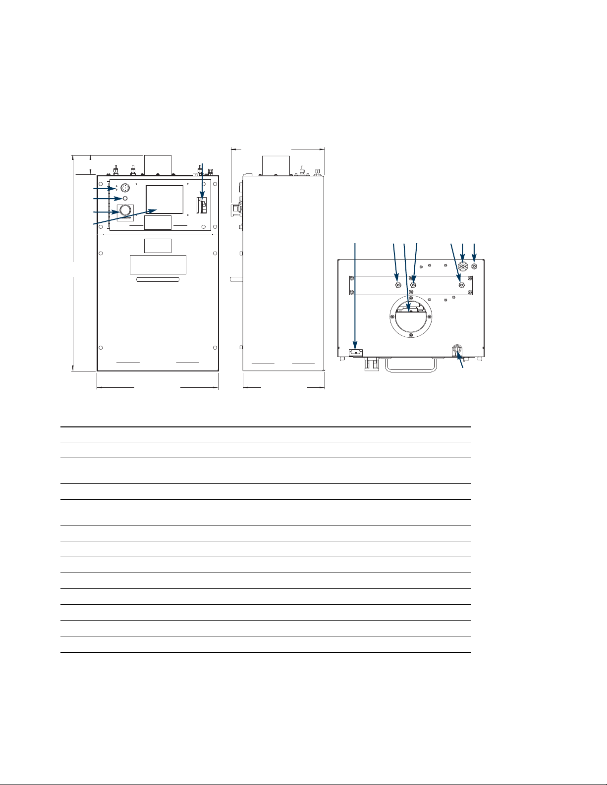
Model EGPS4
Dimensional Information
System Connections
1 Audible alarm Audible warning informs of alarm condition
2 Start Used to begin system operations and to clear alarms
3 EMO When activated, power is removed from the cabinet. The system shuts down.
Front panel and controller remain powered.
4 Touch screen For system status and interface
5 Circuit breaker Provides additional electrical protection to the system and in some models
also acts as an ON/OFF switch for the system
6 Remote alarm interface Allows for remote alarm input and output with female 15 pin DB connector
7 Regen gas vent Exhausts regen gas
8 Exhaust vent Allows ventilation
9 Process gas input Inlet gas (not purified)
10 Process gas output Outlet gas (purified)
11 Reference Atmospheric reference for the internal enclosure flow sensor
12 Instrument air Supplies gas to the air-operated control valves
13 A/C power input Power connection
Enclosure Information
The ventilated enclosure is designed for indoor applications only. The enclosure has mounting locations on
the back surface. The front panel is removable.
457 mm (18.0″)
76 mm (3.0″)
305 mm (12.0″)
342 mm (13.46″)
813 mm
(32.0″)
5
1
2
3
4
Side view
Top view
Front view
6 7 98 121110
13
AERONEX® H SERIES GAS PURIFICATION SYSTEM
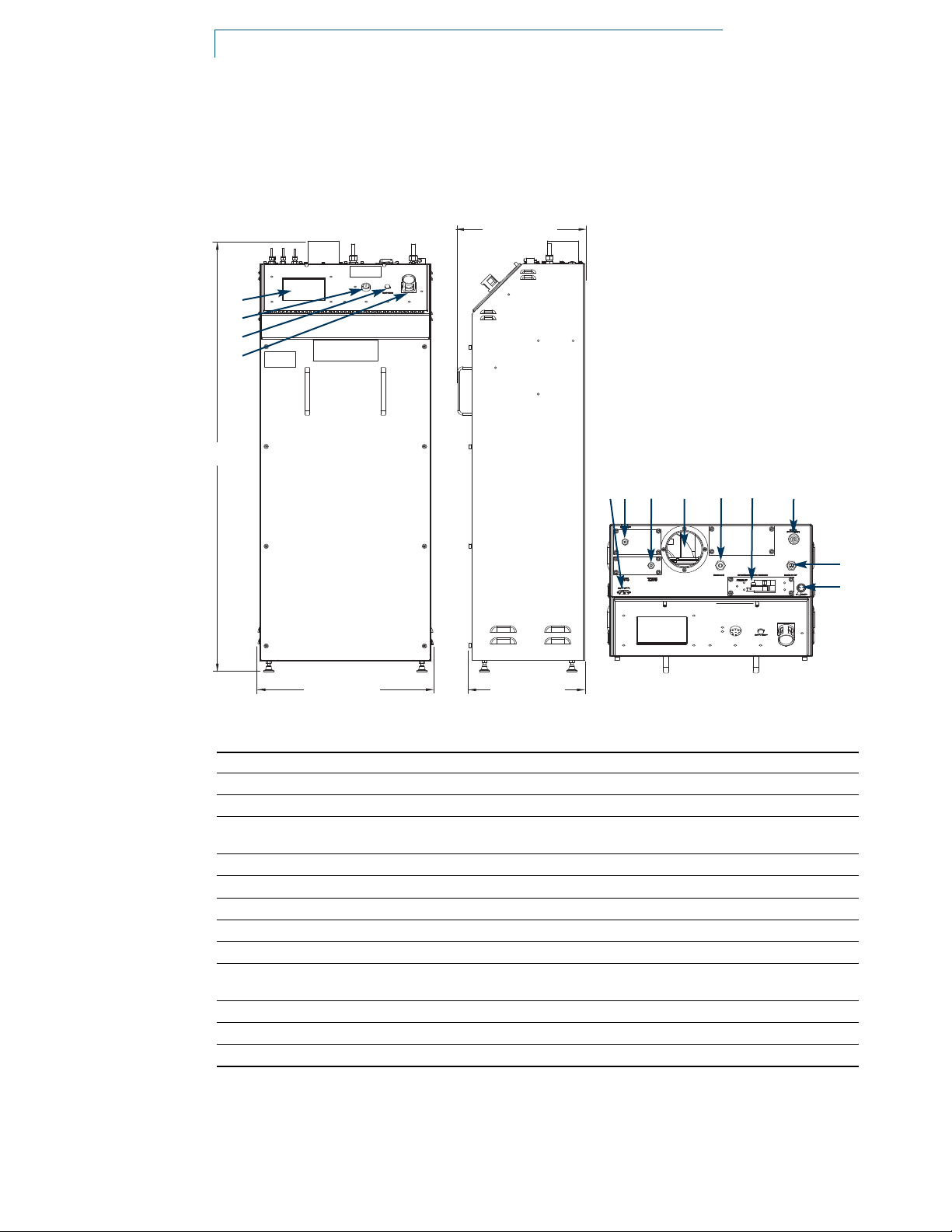
Model EGPS8
Dimensional Information
System Connections
Enclosure Information
The ventilated enclosure is designed for indoor applications only. The enclosure has bolt down locations on
the bottom surface. The front panel is removable.
572 mm (22.50″)
Top view
379 mm (14.92″)
416 mm (16.38″)
1421 mm
(55.94″)
Side view
1 Touch screen For system status and interface
2Audible alarm Audible warning informs of alarm condition
3 Start Used to begin system operations and to clear alarms
4 EMO When activated, power is removed from the cabinet. The system shuts down.
Front panel and controller remain powered.
5 Remote alarm interface Allows for remote alarm input and output with female 15 pin DB connector
6 Instrument air Supplies gas to the air-operated control valves
7 Regen gas vent Exhaust regen gas
8Exhaust vent Allows ventilation
9 Process gas input Inlet gas (not purified)
10 Circuit breaker Provides additional electrical protection to the system and in some models
also acts as an ON/OFF switch for the system.
11Reference Atmospheric reference for the internal enclosure flow sensor
12 Process gas output Outlet gas (purified)
13 A/C power input Power connection
1
2
3
4
12
13
Front view
65 7 8 9 1110

622 mm (24.50″)
Top view
454 mm (17.88″)
1831 mm
(72.08″)
Side view
System Connections
1 Touch screen For system status and interface
2 Audible alarm Audible warning informs of alarm condition
3 Start Used to begin system operations and to clear alarms
4 EMO When activated, power is removed from the cabinet. The system shuts down.
Front panel and controller remain powered.
5 Remote alarm interface Allows for remote alarm input and output with female 15 pin DB connector
6 Regen gas input 1 Nitrogen input
7 Regen gas input 2 Hydrogen input
8 Process gas input Inert gas (not purified)
9 Fire sensor located below cover
10 Exhaust vent Allows ventilation
1
1 Process gas output Outlet gas (purified)
12 Gas monitor located below cover
13 Regen gas vent Exhausts regen gas
14 Instrument air Supplies gas to the air-operated control valves
15 Reference Atmospheric reference for the internal enclosure flow sensor
16 Circuit breaker Provides additional electrical protection to the system and in some models
also acts as an ON/OFF switch for the system
17 A/C power input Power connection
Enclosure Information
The ventilated enclosure is designed for indoor applications only. The enclosure has bolt down locations on
the bottom surface. The front panel is removable.
65 87 9 10 11 13 1412
1
2
3
4
15
16
17
102 mm (4.03″)
Model EGPS12
Dimensional Information
Front view

AERONEX® H SERIES GAS PURIFICATION SYSTEM
Options
Letter
Available Options (Designator) PGPS4 EGPS4 EGPS8 EGPS12
Automatic bypass manifold A Yes Yes Yes Yes
Manual bypass manifold M Yes N/A Yes Yes
Moisture indicator T Yes Yes Yes Yes
Ordering Information
Part Number
PGPS4 EGPS4 EGPS8 EGPS12
Panel-mounted model for OEM Use with applications Use with applications Use with applications
use and applications requiring requiring a flow rate requiring a flow rate requiring a flow rate
a flow rate up to 120 SLM up to 120 SLM up to 300 SLM up to 1000 SLM
PGPS4H EGPS4H EGPS8H EGPS12H
PGPS4HA EGPS4HA EGPS8HA EGPS12HA
PGPS4HAT EGPS4HAT EGPS8HAT EGPS12HAT
PGPS4HM EGPS4HT EGPS8HM EGPS12HM
PGPS4HMT EGPS8HMT EGPS12HMT
PGPS4HT EGPS8HT EGPS12HT
Automatic Manual
Part Bypass Bypass Moisture
Number Manifold Manifold Indicator
PGPS4H
PGPS4HA Yes
PGPS4HAT Yes Yes
PGPS4HM Yes
PGPS4HMT Yes Yes
PGPS4HT Yes
EGPS4H
EGPS4HA Yes
EGPS4HAT Yes Yes
EGPSHT Yes
Automatic Manual
Part Bypass Bypass Moisture
Number Manifold Manifold Indicator
EGPS8H
EGPS8HA Yes
EGPS8HAT Yes Yes
EGPS8HM Yes
EGPS8HMT Yes Yes
EGPS8HT Yes
EGPS12H
EGPS12HA Yes
EGPS12HAT Yes Yes
EGPS12HM Yes
EGPS12HMT Yes Yes
EGPS12HT Yes
Specifications are subject to change.
Please verify prior to order.

ENTEGRIS, INC.
Corporate Headquarters / 3500 Lyman Boulevard / Chaska, Minnesota 55318 USA
Customer Service Tel. 952-556-4181 / Customer Service Fax 952-556-8022
www.entegris.com
The materials integrity management company
Entegris®and Aeronex®are registered trademarks of Entegris, Inc.
SEMI®is a registered trademark of Semiconductor Equipment and Materials International.
U.S. Patent 6,361,696
©2004–2006 Entegris, Inc. All rights reserved Printed in USA 4507-2676ENT-1206
For More Information
Please call your Regional Customer Service Center
today to learn what Entegris can do for you. Visit
www.entegris.com and select “Regional Customer
Service Centers” for the center nearest you.
Terms and Conditions of Sale
All purchases are subject to Entegris’ “Terms
and Conditions of Sale.” To view and print
this information, visit Entegris’ website at
www.entegris.com and select the Legal Notices
link from the footer found on the home page.
This manual suits for next models
4
Table of contents
Other entegris Industrial Equipment manuals


Popular Industrial Equipment manuals by other brands


Balluff
Balluff BTL PA0400 Series installation guide

CIAS Elettronica S.r.l.
CIAS Elettronica S.r.l. PYTHAGORAS3 manual

ABB
ABB HT567947 Operation manual

Purkeys
Purkeys STATUS 45 VOLT installation guide

INOXPA
INOXPA BCI Series Installation, service and maintenance instructions

WITTUR
WITTUR WRG200 Operating instruction