Man VTA User manual


Table of contents
1 Adjustable turbine nozzle ring (VTA) .................................................................................................... 3
1.1 Range of applications .................................................................................................................3
1.2 Application Examples .................................................................................................................8
1.3 Low-speed propulsion engines from MAN B&W ......................................................................11
2 Overview of series ............................................................................................................................... 14
2.1 VTA on TCA turbocharger .........................................................................................................14
2.2 Dimensions ................................................................................................................................14
2.3 Weights ......................................................................................................................................14
2.4 Casing Positions ........................................................................................................................15
3 Design .................................................................................................................................................. 16
3.1 Characteristics of the Assemblies ...........................................................................................16
3.2 Operation Method of the Adjusting Device ..............................................................................17
4 Systems ............................................................................................................................................... 18
4.1 VTA Control (VCS) ......................................................................................................................18
4.2 Cooling Water System ...............................................................................................................20
4.3 Inflation Air ................................................................................................................................22
5 Engine room planning ......................................................................................................................... 24
5.1 Equipment .................................................................................................................................24
5.2 VTA Control System (VCS) ........................................................................................................24
5.3 Multi Purpose Controller (MPC) ................................................................................................25
5.4 Main Operating Panel (MOP) ....................................................................................................25
5.5 Cabling ......................................................................................................................................26
6 Operation ............................................................................................................................................. 27
6.1 Putting into Operation ...............................................................................................................27
6.2 VTA – Adjustment Ranges and Adjustment Speeds ................................................................27
6.3 Emergency Operation on Failure of the VTA Adjusting Device ...............................................27
7 Maintenance and inspection .............................................................................................................. 29
7.1 Introductory Remarks ...............................................................................................................29
7.2 Cleaning the Variable Turbine Area ..........................................................................................29
7.3 Maintenance of the Adjusting Device ......................................................................................29
7.4 Inspection of the Pipe Systems ................................................................................................29
7.5 Electronic Equipment ................................................................................................................29
8 Matching ............................................................................................................................................. 30
8.1 Matching Procedure ..................................................................................................................30
8.2 Adjusting the Charging Air Pressure ........................................................................................30
2013-12-04 - de
Table of contents
MAN Diesel & Turbo
1 (38)

8.3 Surge Tests ...............................................................................................................................31
9 Scope of supply ................................................................................................................................... 32
9.1 Delivery Scope, VTA and Equipment ........................................................................................32
9.2 Hardware ...................................................................................................................................32
9.3 Software ....................................................................................................................................33
9.4 Cable Sets ..................................................................................................................................33
10 Retrofits – worldwide turbocharger service ...................................................................................... 35
10.1 Retrofitting a Variable Turbine Area ........................................................................................35
10.2 MAN | PrimeServ .......................................................................................................................35
10.3 Worldwide service addresses ...................................................................................................36
Table of contents
2013-12-04 - de
MAN Diesel & Turbo
2 (38)

1 Adjustable turbine nozzle ring (VTA)
1.1 Range of applications
The VTA was designed for applications on turbocharged large diesel engines
with different load profiles. Due to its adjustability, the VTA adapts the turbo-
charging characteristics so that the engine works efficiently over a wide load
range.
In order to meet the requirements of modern large diesel engines, a variable
fresh air supply is required. One particularly efficient way of achieving this is
to use an adjustable turbine nozzle ring, or VTA. This modifies the pressure
level in the engine by adapting the narrowest nozzle ring cross section for the
air flow. The area through which the air flows is modified by adjusting the
guide vanes of the turbine nozzle ring.
If adjusting the guide vanes makes the air flow cross section narrower, this
increases the speed of the air flow to the turbine wheel. This increases the
turbocharger speed, thereby causing the charge pressure on the compres-
sor side to rise.
The VTA technology is available for all turbocharger sizes in the TCA Series
and can be used with both 2-stroke and 4-stroke engines. Both diesel
engine and gas-powered engine applications can be improved significantly
using a VTA.
Engine performance is optimised in accordance with customer requirements
by means of adapted control programs.
See table Overview – VTA range of applications.
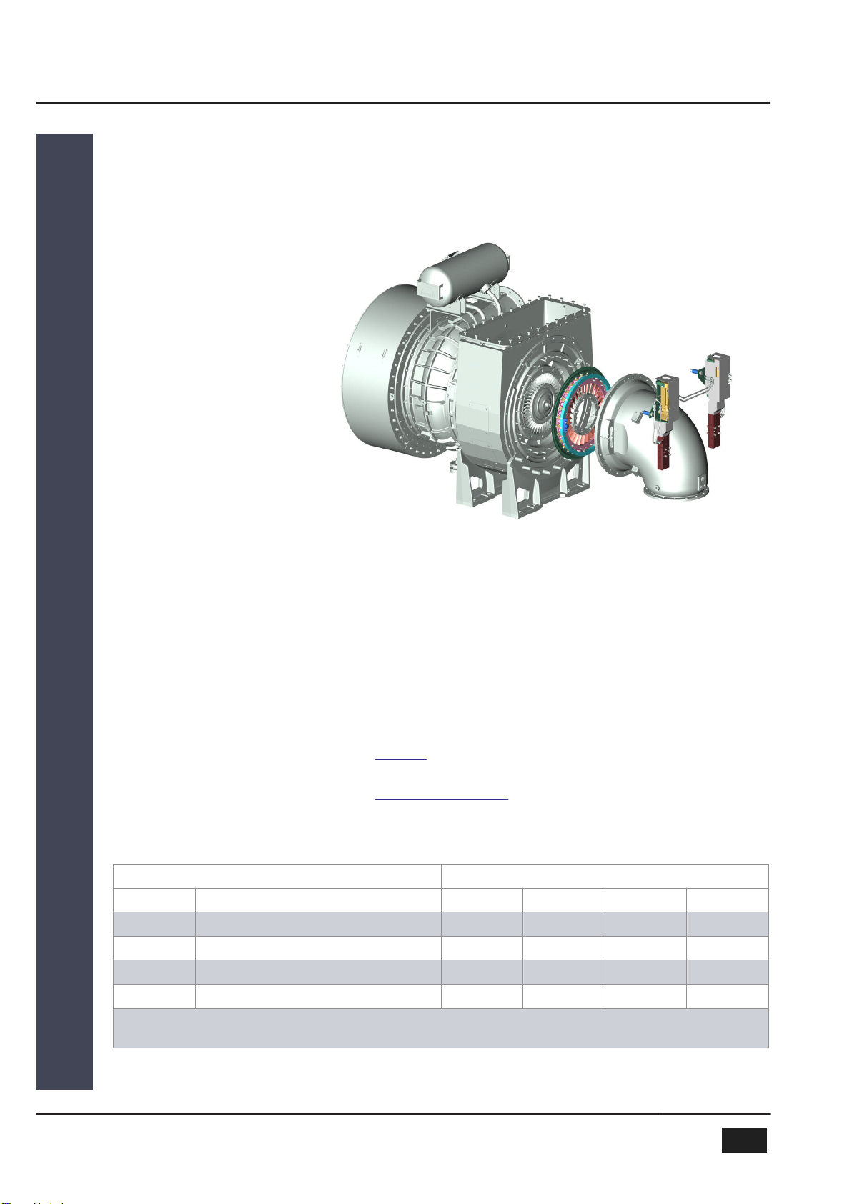
Figure 1: TCA turbocharger with adjustable turbine nozzle ring
Functional Principle
VTA for TCA Turbocharger
2013-12-04 - de
1 Adjustable turbine nozzle ring (VTA) 1.1 Range of applications
MAN Diesel & Turbo 1
EN-US 3 (38)

1 Adjustable turbine nozzle ring (VTA) 1.1 Range of applications
2013-12-04 - de
1MAN Diesel & Turbo
4 (38) EN-US

Application Functional principle Effect
2-stroke diesel engine
▪Scavenge air pressure at partial
load is increased by closing the
VTA:
▪At partial load either
Economy Mode (Mode 1.)
Increased ignition pressure for reduction
of SFOC 3)
Reduced fuel consumption
(NOx increased) or
Emission Mode (Mode 2.)
Ignition pressure is kept constant by
ignition retard.
▪Compensation of ambient tem-
perature influences on scavenge
pressure
▪Closing on acceleration
▪Compensation of extracted gas
flows (e.g. for power turbine
applications, see “Power tur-
bine” line)
▪Plants with EGR 4):
Scavenge air pressure kept con-
stant when EGR rate is modified
3) Specific fuel oil consumption
4) Exhaust gas recirculation
Reduced NOx emissions
(Fuel consumption slightly higher than
Mode 1.).
In conjunction with a variable injection
system and appropriate optimization, the
VTA enables reduced consumption and
flexible changing between Mode 1. and
Mode 2.
▪Slight increase in consumption at
full load
▪Shifting of auxiliary blower
switch-off point towards lower
outputs
▪Elimination of a bypass for scav-
enge pressure compensation at
extremely low intake tempera-
tures
(“Arctic conditions”)
▪Improved load application behav-
ior
▪Additional improvement of partial
load performance by shifting the
maximum efficiency towards a
lower engine load
▪Exhaust gas temperatures at
partial load reduced
NOTE!
In the dedicated “Economy Mode”
(Mode 1.), the VTA rating must be
adapted to the NOx limit values.
Table 1: VTA range of applications on 2-stroke diesel engine
2013-12-04 - de
1 Adjustable turbine nozzle ring (VTA) 1.1 Range of applications
MAN Diesel & Turbo 1
EN-US 5 (38)

Application Functional principle Effect
4-stroke diesel engine ▪VTA closes at partial load
▪Compensation of ambient tem-
perature influences on charge
pressure
▪Closing on acceleration
▪Compensation of extracted gas
flows (e.g. for power turbine
applications, see “Power tur-
bine” line)
▪Plants with EGR 4):
Charge air pressure kept con-
stant when EGR rate is modified
▪HAM 5) applications:
Increased water content at par-
tial load.
4) Exhaust gas recirculation
5) Humid air motor
▪Reduced fuel consumption at
partial load
▪Increased NOx emissions ⇨
With appropriate rating within the
limit values or constant cycle val-
ues, similar to 2-stroke
▪Reduction of exhaust gas tem-
peratures at partial load
▪Elimination of blow-off valves
▪Improved load application behav-
ior
▪Reduction of soot emissions in
the case of low load and load
application
▪Additional improvement of partial
load performance by shifting the
maximum efficiency towards a
lower engine load
Table 2: VTA range of applications on 4-stroke diesel engine
Application Functional principle Effect
Gas-powered engine ▪VTA opens at partial load
▪Compensation of ambient tem-
perature influences on charge
pressure
▪Closing on load application to
prevent overgreasing
▪Variation of the charge pressure
to adapt to changing gas quali-
ties
▪Reduced fuel consumption due
to increased turbocharging effi-
ciency compared with blow-off
valves or throttle
▪Elimination of blow-off valves/
throttle
Table 3: VTA range of applications on gas-powered engine
Application Functional principle Effect
Dual-fuel engine See gas-powered and diesel engine See gas-powered and diesel engine
Table 4: VTA range of applications on dual-fuel engine
Application Functional principle Effect
Test engine ▪Adaptation of the charge air
pressure to changing engine
parameters
▪Elimination of conversions
▪Infinitely adjustable setting of the
charge air pressure
Table 5: VTA range of applications on test engine
Application Functional principle Effect
Power turbine 1. VTA only on power turbine
▪“Closing” of the VTA to throttle
the power turbine output
▪Increased turbocharging effi-
ciency at a given power turbine
output, compared with power
turbine control by means of con-
trol flaps, due to elimination of
pressure losses
1 Adjustable turbine nozzle ring (VTA) 1.1 Range of applications
2013-12-04 - de
1MAN Diesel & Turbo
6 (38) EN-US

Application Functional principle Effect
2. VTA on every turbocharger and power turbine
▪“Closing” of all VTAs with con-
stant area factor (and thus con-
stant bypass ratio)
▪In full load range:
“Closing” of the VTA of the
power turbine to throttle the
power turbine output,
“opening” of the VTAs on the
turbochargers to limit the charge
pressure.
▪At partial load:
“Closing” of the VTA to throttle
the power turbine output, analo-
gous to 1.
▪Increased power turbine output
and reduced SFOC by increasing
the scavenge air pressure (see
“2-stroke engine” line) and
exhaust gas pressure
▪Increased turbocharging effi-
ciency at a given power turbine
output, compared with power
turbine control by means of
bypass
▪Increased turbocharging effi-
ciency at a given power turbine
output – see 1.
Table 6: VTA range of applications on power turbine
Application Functional principle Effect
Plant technology ▪Compensation of flow rate fluc-
tuations
▪Closing during a starting opera-
tion
▪Elimination of control flaps prone
to a high degree of loss
Table 7: VTA range of applications in plant technology
2013-12-04 - de
1 Adjustable turbine nozzle ring (VTA) 1.1 Range of applications
MAN Diesel & Turbo 1
EN-US 7 (38)
1.2 Application Examples
1000
1500
2000
2500
3000
3500
4000
20 30 40 50 60 70 80 90 100
pscav in mbar
Engine load in %MCR
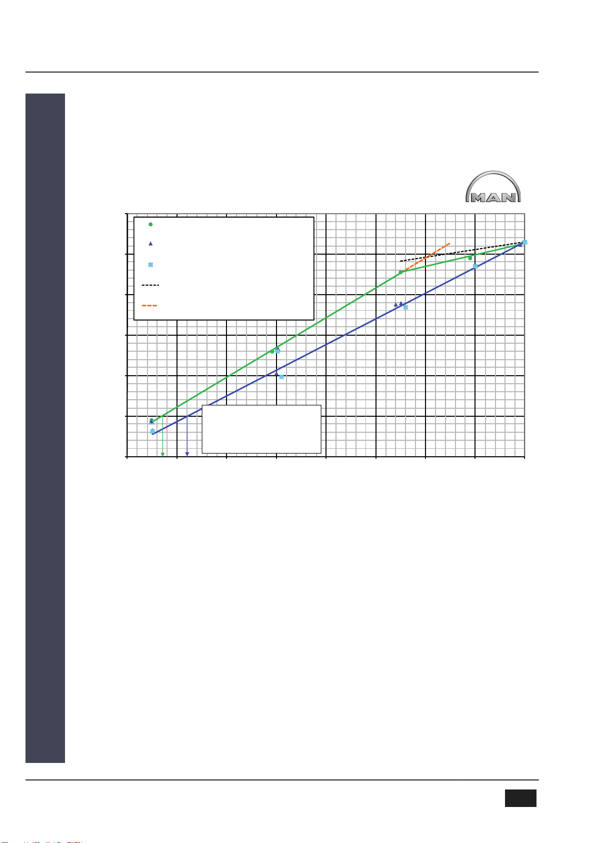
TCA55-21004V on 6S46MC-C
S pe c ific a tio n TC A5 5-21 00 4V, VT A c lo s ing
S pe c ific a tio n TC A5 5-21 00 4V, VT A ope n
S ta nd ard s p ec ific ation T C A55 -20 027 w ith fixed
noz z le ring
Max. a llo w ab le ps c a v
S am e s p ec ific ation as T C A55-210 04V but w ith
fixe d n oz z le ring
A ux. B lowe r switc h po int
with V TA = 2 7% Lo ad
A ux. B lowe r switc h po int
without VTA = 3 2% L oa d
pscav Scavenge air pressure
MCR Maximum Continuous Rating
Figure 2: Increased scavenge air pressure with TCA55-21V on 6S46MC-C TIER I
MAN 2-stroke diesel engine 6S46MC-C with TCA55-21V turbocharger
The diagram Increased scavenge air pressure with TCA55-21V on 6S46MC-
C illustrates the mode of operation of the VTA on the 6S46MC-C engine.
The upper green line shows the scavenge air pressure that is set when the
VTA is closed towards partial load (“VTA closing”). In contrast, the scavenge
air pressures for the VTA test specification TCA55-21004V with the nozzle
ring remaining open for partial load (“VTA open” – ▲ dark line, bottom) and
the initial specification TCA55-20027 with rigid nozzle ring are also shown (■
light points).
Since, for this engine, no device is offered for varying the start of injection, an
increase in the ignition pressure at partial load can only be achieved by
means of the scavenge air pressure. If a specification with a smaller rigid
nozzle ring were to be selected, a reduction of the maximum available power
VTA on 2-stroke diesel
engine
1 Adjustable turbine nozzle ring (VTA) 1.2 Application Examples
2013-12-04 - de
1MAN Diesel & Turbo
8 (38) EN-US
would be required in order not to exceed the maximum value for the ignition
pressure in the load range of approx. 80-100% MCR. This can be avoided
by opening the VTA from 75% MCR onwards.
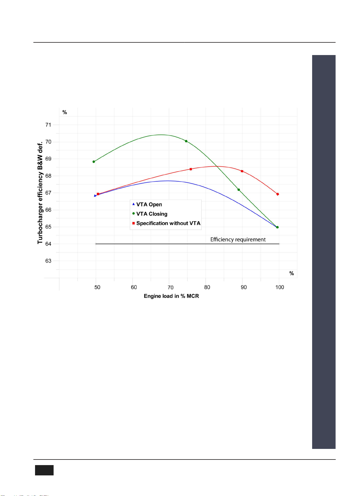
MCR Maximum Continuous Rating
Figure 3: Turbocharger efficiencies with TCA55-21V on 6S46MC-C engine
In the diagram Turbocharger efficiencies with TCA55-21V on 6S46MC-C
engine, the efficiency characteristic of the VTA rating is plotted with the exist-
ing specification optimized for full load. With a closing nozzle ring, a marked
increase in the efficiency can be seen below 85% MCR.
In this case, the margin to the required efficiency rating has been used for
extreme optimization of the partial load performance. The difference between
the specification with and without VTA is thus extremely positive at partial
load and negative at full load – but still meeting all requirements.
Increased
turbocharger efficiency
2013-12-04 - de
1 Adjustable turbine nozzle ring (VTA) 1.2 Application Examples
MAN Diesel & Turbo 1
EN-US 9 (38)
Gas-powered operation of the 7L51/60DF dual-fuel engine with
TCA55-41V turbocharger
For stable, knock-free combustion, gas-powered engines require a limited
gas/air ratio, which is achieved by regulating the charge pressure. If the load
drops below 50%, a significant reduction of the charge pressure is required.
Furthermore, a control reserve must be provided for load applications and
high intake temperatures in the load range of 50-100% MCR. For a rigid
geometry, this can be achieved by means of blow-off during operation at
normal conditions or partial load with significant charging efficiency losses, or
efficiently by opening the VTA position. Moreover, an open VTA position at
partial load allows a more efficiency-optimized setting than a rigid turbine
nozzle ring.
The resulting increase in charging efficiency with VTA compared with the
bypass concept is illustrated in the diagram Improvement of the charging effi-
ciency with TCA55-41V on 7L51/60DF engine.
2 0 3 0 4 0 5 0 6 0 7 0 8 0 9 0 1 0 0 11 0
Charging efficiency in %
V TA
B yp as s
MCR Maximum Continuous Rating
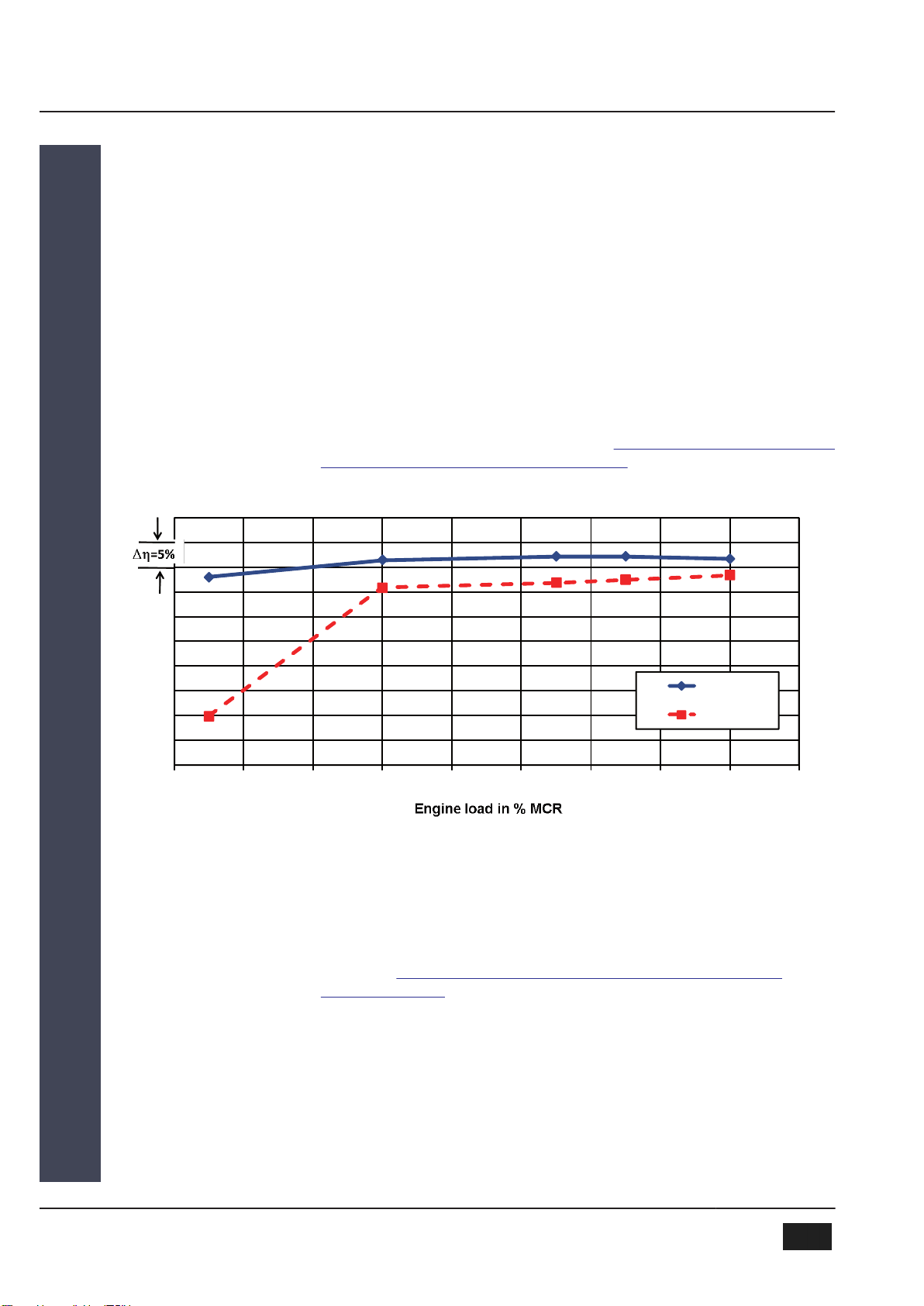
Figure 4: Improvement of the charging efficiency with a TCA55-41V on an 7L51/60DF engine
For a gas-powered engine operated predominantly in the load range of 50 –
100%, this results in a potential improvement of approx. 0.5 percentage
points in the thermal efficiency of the engine.
See Figure Improvement of the thermal efficiency with TCA55-41V on
7L51/60DF engine.
Fuel saving for 4-stroke gas-
powered engine
Increased
charging efficiency
Thermal efficiency
1 Adjustable turbine nozzle ring (VTA) 1.2 Application Examples
2013-12-04 - de
1MAN Diesel & Turbo
10 (38) EN-US

4 0 5 0 6 0 7 0 8 0 9 0 1 0 0 11 0
Engine thermal efficiency in %
Engine load in % MCR
V TA
B yp as s
∆η=1%
MCR Maximum Continuous Rating
Figure 5: Improvement of the thermal efficiency with a TCA55-41V on an 7L51/60DF engine
1.3 Low-speed propulsion engines from MAN B&W
The following tables summarize the fuel-saving potential existing for
MAN B&W engines. All SFOC values refer to the SFOC for a load of 100%
for a standard L1 engine.
SFOC-optimized load range Tuning method SFOC change [g/kWh]
35% 50% 65% 80% 100%
High load (85-100%) Standard L1 engine 3.5 -1 -3.5 -3.5 0
Partial load (50-85%) VTA 0.5 -4 -6.5 -4.5 0.5
Low load (25-70%) VTA -1.5 -6 -8.5 -3.5 0.5
Standard L1 engine – turbocharger without adjustable turbine nozzle ring
VTA – turbocharger with adjustable turbine nozzle ring
Table 8: Optimization potential – ME/ME-C Tier II engines, SMCR = L1
2013-12-04 - de
1 Adjustable turbine nozzle ring (VTA) 1.3 Low-speed propulsion engines from MAN B&W
MAN Diesel & Turbo 1
EN-US 11 (38)

Figure 6: Reduction of the specific fuel consumption SFOC of ME/ME-C engines by
means of VTA
SFOC-optimized load range Tuning method SFOC change [g/kWh]
35% 50% 65% 80% 100%
High load (85-100%) Standard L1 engine 4 0 -2.5 -3 0
Partial load (50-85%) VTA 2 -2 -4.5 -4 2
Low load (25-70%) VTA 1 -3 -5.5 -3 1
Standard L1 engine – turbocharger without adjustable turbine nozzle ring
VTA – turbocharger with adjustable turbine nozzle ring
Table 9: Optimization potential – MC/MC-C/ME-B Tier II engines, SMCR = L1
1 Adjustable turbine nozzle ring (VTA) 1.3 Low-speed propulsion engines from MAN B&W
2013-12-04 - de
1MAN Diesel & Turbo
12 (38) EN-US
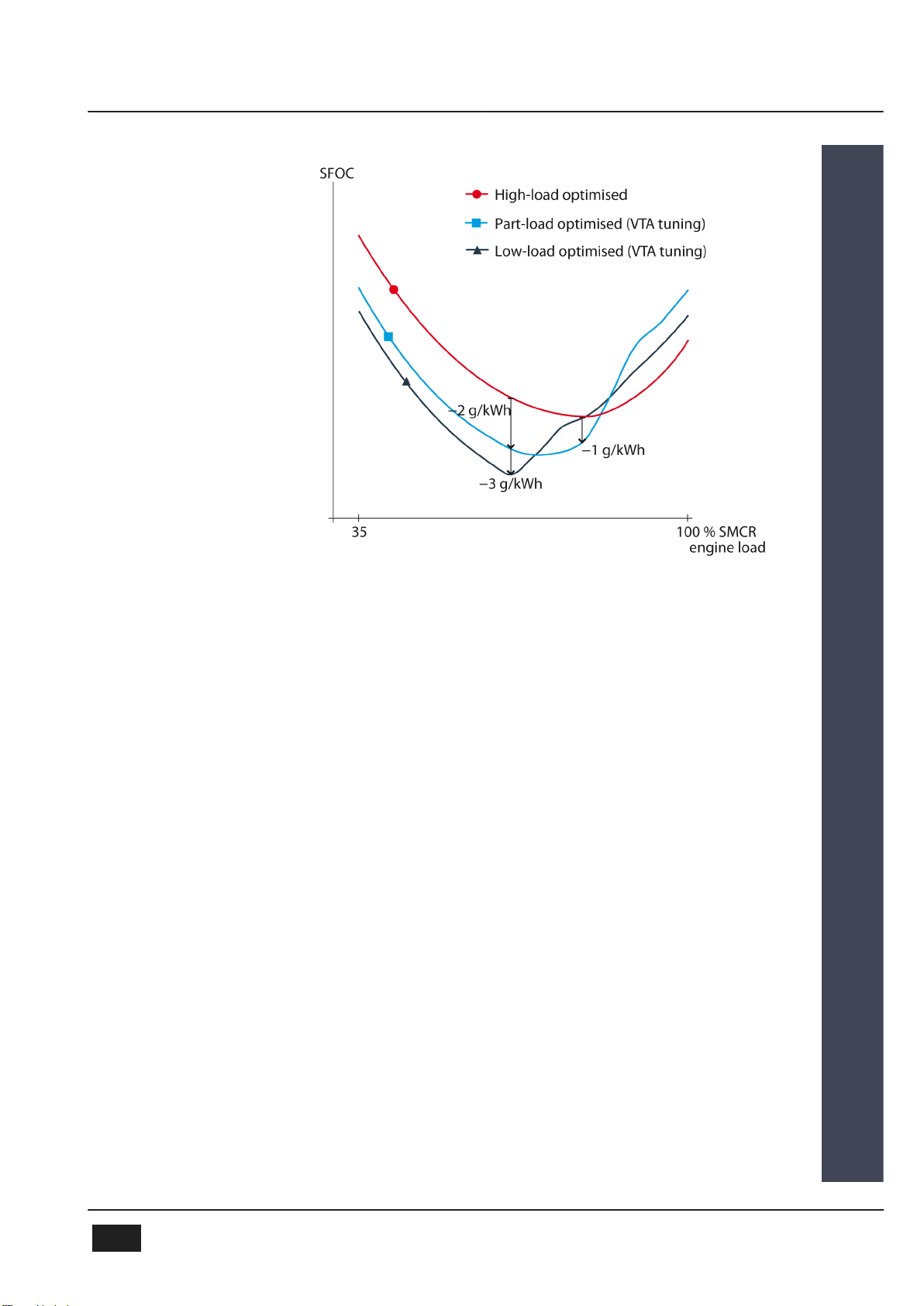
Figure 7: Reduction of the specific fuel consumption SFOC of MC/MC-C/ME-B
engines by means of VTA
For a specific L1 engine, the SFOC profile can be taken directly from the
tables above. For example, an S70ME-C8.2 at a load of 65% and with an L1
SFOC of 169 g/kWh, optimized for partial load with VTA tuning, has a con-
sumption of 169 - 6.5 g/kWh = 162.5 g/kWh.
The tuning methods specified above are also available for derated engines
with various SMCRs. The load-dependent standard SFOC profile is different
for a derated engine; the difference specified above between the individual
tuning methods and the standard engine is the same, however.
For engines with turbochargers featuring conventional efficiency, optimization
is only possible at high load.
The specified methods and options are explained below.
2013-12-04 - de
1 Adjustable turbine nozzle ring (VTA) 1.3 Low-speed propulsion engines from MAN B&W
MAN Diesel & Turbo 1
EN-US 13 (38)
2 Overview of series
2.1 VTA on TCA turbocharger
Figure 8: TCA turbocharger with adjustable turbine nozzle ring
2.2 Dimensions
The dimensions of the turbocharger are not changed by using an adjustable
turbine nozzle ring.
Overall dimensions for TCA turbocharger:
See Project Guide “TCA Turbochargers”.
Depending on the engine plant, an additional control cabinet or switch box is
required to house the VTA controller for the adjustable turbine nozzle ring.
Description of the required components for the VTA controller:
See chapter Systems / VTA control.
Dimensions and installation of the required control cabinets:
See chapter Engine room planning.
2.3 Weights
Subassembly Turbocharger
Number Designation TCA55 TCA66 TCA77 TCA88
510 Adjustable turbine nozzle ring 78 kg 131 kg 220 kg 361 kg
511 Adjustment device 40 kg 40 kg 56 kg 56 kg
549 Sealing air pipe 2 kg 2 kg 3 kg 3 kg
–m+1) 100 kg 110 kg 140 kg 190 kg
1) m+ = weight increase of a TCA turbocharger with VTA compared with a TCA turbocharger of the same size with-
out VTA
Table 10: Weights of individual VTA components
Overall dimensions
Control cabinet
2 Overview of series 2.3 Weights
2013-12-04 - de
2MAN Diesel & Turbo
14 (38) EN-US

TIP The VTA can generally be implemented in all TCA turbocharger
types and sizes.
To obtain weight specifications for VTA components of TCA turbochargers
that are not listed here, please contact our Technical Sales department.
e-mail: [email protected]
2.4 Casing Positions
Use of the adjustable turbine nozzle ring does not restrict the rotatability of
individual casings on TCA turbochargers.
TIP Possible casing positions for TCA turbochargers:
See Project Guide “TCA Turbochargers”.
The adjustment device for the turbine nozzle ring is fastened to the gas
admission casing and cannot be rotated separately.
The servomotors of the adjustment device generally point in the direction of
the exhaust gas pipe – see Figure 90° gas admission casing with VTA adjust-
ment device.
501.000 Gas-admission casing E Exhaust-gas inlet
510.000 Variable turbine area
511.000 Adjusting device
Figure 9: 90° gas-admission casing with VTA adjusting device
Installation position
of adjustment device
2013-12-04 - de
2 Overview of series 2.4 Casing Positions
MAN Diesel & Turbo 2
EN-US 15 (38)
3 Design
3.1 Characteristics of the Assemblies
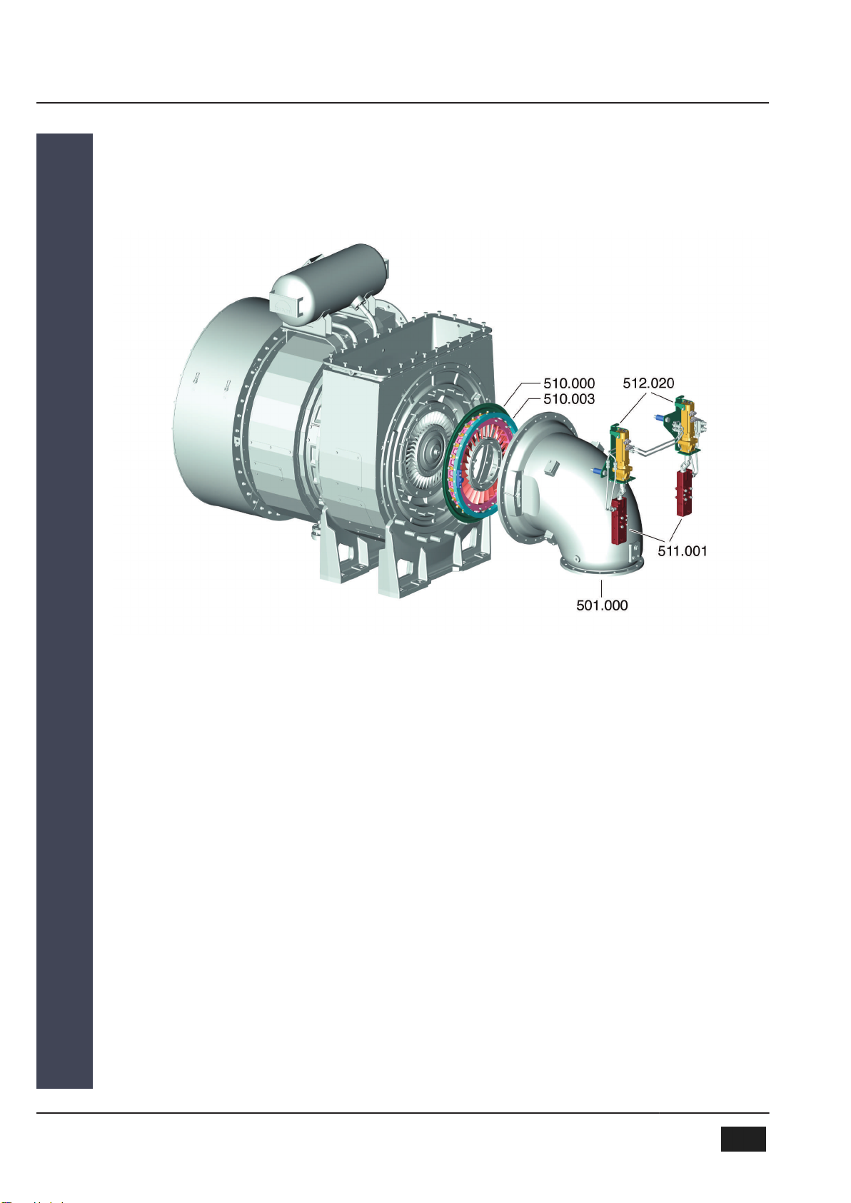
501.000 Gas admission casing
510.000 Adjustable turbine nozzle ring
510.003 Setting ring
511.001 Spindle drive
512.020 Servomotor
Figure 10: TCA turbocharger with adjustable turbine nozzle ring (VTA)
Adjustable Turbine Nozzle Ring
The cast turbine guide vanes of the adjustable turbine nozzle ring (510.000)
have the same profile as the fixed nozzle ring in order to benefit from the
advantages of low vibration and good flow characteristics.
Adjustment Device
The principal components of the adjustment device are the two spindle
drives (511.001) which are responsible for converting the rotational motion of
the servomotors (512.020) to a linear motion for adjustment of the VTA.
Subassembly 510
Subassembly 511
3 Design 3.1 Characteristics of the Assemblies
2013-12-04 - de
3MAN Diesel & Turbo
16 (38) EN-US

3.2 Operation Method of the Adjusting Device
The adjustable turbine nozzle ring is driven by two servomotors mounted on
the adjustment device. The motor speed is reduced and the torque
increased by means of a planetary gear unit. A Cardan joint transfers the tor-
que from the servomotor to the spindle drive. There is one spindle drive for
each servomotor.
In each spindle drive is a shaft with axial needle bearings. This shaft rotates
as the torque is applied. The rotational motion of the spindle shaft is con-
verted into a translational motion by means of a slotted nut.
The motion of the nuts of both spindle drives is transferred to the carriers
fastened to the setting ring, thereby inducing a rotational motion of the set-
ting ring.
There are setting levers evenly distributed around the circumference – one
setting lever per turbine guide vane – mounted in the setting ring. The setting
levers are positively connected to the turbine guide vanes, which are
mounted in the outer guide ring. The torque imparted by the setting ring to
the levers induces a rotational motion of the turbine guide vanes.
NOTE For the adjustment of the turbine nozzle ring, the two servomo-
tors, operated in parallel, must be rotated in opposite directions.
Servomotors
(512.020)
Spindle drive
(511.001)
Setting ring
(510.003)
Adjustable
turbine guide vanes
2013-12-04 - de
3 Design 3.2 Operation Method of the Adjusting Device
MAN Diesel & Turbo 3
EN-US 17 (38)

4 Systems
4.1 VTA Control (VCS)
Various controller variants are available in order to be able to cover all appli-
cations.
Detailed list of the components required for this:
See chapter Scope of supply / Scope of supply of VTA and equipment.
VTA Variable Turbine Area
VCS VTA Control System
MPC Multi Purpose Controller
MOP Main Operating Panel
SACS Scavenging Air Control Software
ECS Engine Control System
For this application, parameters including the following are required for
adjustment of the VTA:
▪Filling of fuel index transmitter or regulator
▪Scavenge air pressure
These parameters are processed in the Multi-purpose controller (MPC) of the
VTA control system (VCS). The MPC supplies the VTA control system with
signals for adjusting the VTA.
The following parameters are output:
▪Slow Down
▪Warnings for the safety system
Explanation of terms
VTA on MC/MC-C
two-stroke engine
4 Systems 4.1 VTA Control (VCS)
2013-12-04 - de
4MAN Diesel & Turbo
18 (38) EN-US
Table of contents
Popular Industrial Equipment manuals by other brands

Magnaflux
Magnaflux Universal WE TOUCH with TCODE operating manual

ITEM
ITEM LRE 8 D25 ZU 80 R50 Notes on Use and Installation

Essemtec
Essemtec Fox Maintenance manual

Graziadio & C.
Graziadio & C. K Series Assembly instructions

Irontite Products
Irontite Products Kwik-Way SVS II Deluxe Instruction manual and parts list

TECNA
TECNA 9354G instruction manual


Full Spectrum Laser
Full Spectrum Laser MUSE MOPA user manual

HYTROL
HYTROL 190-NSP Series Installation and maintenance manual

Miller
Miller INTELLIMATIC SS-12M owner's manual

ABB
ABB HT603383 Operation manual

Jäger
Jäger Chopper 6500 H manual

FLENDER
FLENDER B H 23 28 Series Assembly and operating instructions