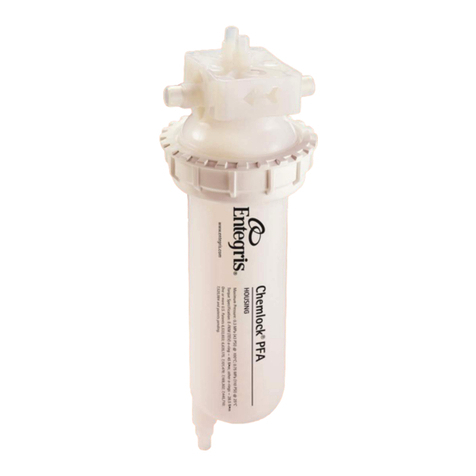
entegris Optimizer ST2 Guide

MICROCONTAMINATION CONTROL |MANUAL
Optimizer®ST2 Filter Manifold
Installation and use manual

OPTIMIZER ST2 FILTER MANIFOLD
1Entegris, Inc | Installation and Use Manual
TABLE OF CONTENTS
—
Introduction ....................................................................... 2
Specifications .................................................................... 2
Ordering Information ..................................................... 2
Manifold and Filter Parts ................................................ 3
Dimensions ........................................................................ 4
Mounting Plate (Common to all Types) ................... 4
Tube Type Manifold
Part Number AMVT***01 ................................... 4
Flowell 60 Elbow Type Manifold
Part Number AMVXL22KT .................................. 5
Part Number AMVXL32KT .................................. 6
Part Number AMVXL42KT .................................. 7
Flowell 80EX Elbow Type Manifold
Part Number AMVZL22KT .................................. 8
Part Number AMVZL32KT .................................. 9
Part Number AMVZL42KT ................................ 10
Safety Instructions .......................................................... 11
Preparation for Installing the
Optimizer ST2 Manifold ................................................ 11
Installing the Optimizer ST2 Manifold ...................... 12
Attaching and Removing the Filter ............................ 16
Preparing the Line Before Replacing the Filter .... 16
Preparing the Filter to be Replaced ........................ 16
Removing the Filter or Flushing Shell .................... 16
Attaching the Filter or Flushing Shell ........................ 18
Filter Startup .................................................................... 20
Replacing the O-rings .................................................. 21
Removing the O-rings ................................................ 21
Attaching the O-rings .................................................. 21
Limited Warranty ............................................................ 22
For More Information ................................................... 22
Terms and Conditions of Sale ..................................... 22

2
OPTIMIZER ST2 FILTER MANIFOLD
Installation and Use Manual | Entegris, Inc.
INTRODUCTION
—
The Optimizer®ST2 filter manifold is designed for
use with Optimizer point-of-use (POU) liquid filters
to minimize contamination risk when handling filter
cartridges. Using Entegris’ Connectology®technology,
the Optimizer filter quickly connects and seals to the
ST2 manifold, which enables rapid filter change-outs
without tools or draining. By limiting hazardous
chemical handling during installation, the filter mani-
fold speeds up installation and reduces downtime
while also increasing operator safety.
CAUTION: To reduce the safety risk of chemical
leakage, carefully follow these instructions.
SPECIFICATIONS
—
Materials Metal plates Stainless steel
Release tub Polyacetal
Connectors PFA
O-rings on
manifold
OM: Kalrez®
Connections Tube, Flowell®60, Flowell 80EZ
(See part number table for sizes.)
Maximum
operating
conditions
Maximum operating pressure:
0.39 MPa (3.9 bar, 57psi) at 25°C (77°F)
Maximum operating temperature:
40°C (104°F)
ORDERING INFORMATION
—
OPTIMIZER ST2 MANIFOLD
Quantity: 1 each/box
Tube Type (standard size)
Part number Inlet/outlet Vent port
AMVT442K1 12.7 mm (⁄") tube 6.35 mm (⁄")
AMVT332K1 9.53 mm (⁄") tube 6.35 mm (⁄")
AMVT222K1 6.35 mm (⁄") tube 6.35 mm (⁄")
Flowell 60 Elbow Type
AMVXL42KT 12.7 mm (⁄") 6.35 mm (⁄")
AMVXL32KT 9.53 mm (⁄") 6.35 mm (⁄")
AMVXL22KT 6.35 mm (⁄") 6.35 mm (⁄")
Flowell 80EZ Elbow Type
AMVZL42KT 12.7 mm (⁄") 6.35 mm (⁄")
AMVZL32KT 9.53 mm (⁄") 6.35 mm (⁄")
AMVZL22KT 6.35 mm (⁄") 6.35 mm (⁄")
Replacement O-ring
Part number Description
10456J Kalrez O-ring for ST2 manifold
OM version, 10/bag
CAUTION: If higher pipeline tension is expected, it is
recommended to use a double O-ring combination
of the OM manifold and OF filter.

OPTIMIZER ST2 FILTER MANIFOLD
3Entegris, Inc | Installation and Use Manual
MANIFOLD AND FILTER PARTS
—
Manifold
Outlet
Inlet
Vent
Release tab
Lever
Filter guide
Filter
Tab

4
OPTIMIZER ST2 FILTER MANIFOLD
Installation and Use Manual | Entegris, Inc.
DIMENSIONS
—
MOUNTING PLATE (COMMON TO ALL TYPES)
TUBE TYPE MANIFOLD (PART NUMBER AMVT***01)
2X Ø6.0 mm
(0.24")
42.5 mm
(1.67")
50.8 mm
(2.0")
65.0 mm
(2.56")
19.0 mm
(0.75")
4X Ø4.5 mm (0.18")
R 3.0 mm (0.12")
23.0 mm
(0.91")
6.5 mm (0.26")
9.2 mm
(0.36")
22.2 mm
(0.87")
2.0 mm (0.08")
Top View
Front View Side View
104.5 mm
(4.11")
40.8 mm
(1.60") 62.0 mm
(2.44")
139.1 mm
(5.48")
25.3 mm
(1.00")
25.3 mm
(1.00")
95.5 mm
(3.76")
150.0 mm
(5.91")
32.4 mm
(1.27")
16.0 mm
(0.63")
102.8 mm
(4.05")
205.0 mm (8.07")
174.0 mm
(6.85")
126.0 mm
(4.96")

OPTIMIZER ST2 FILTER MANIFOLD
5Entegris, Inc | Installation and Use Manual
DIMENSIONS (CONTINUED)
—
FLOWELL 60 ELBOW TYPE MANIFOLD (PART NUMBER AMVXL22KT)
Top View
Front View Side View
104.5 mm
(4.11")
40.8 mm
(1.60") 62.0 mm
(2.44")
139.1 mm
(5.48")
25.3 mm
(1.00")
25.3 mm
(1.00")
95.5 mm
(3.76")
60.0 mm
±2 mm
(2.36"
±0.08") 32.4 mm
(1.27")
16.0 mm
(0.63")
102.8 mm
(4.05")
205.0 mm (8.07")
174.0 mm
(6.85")
Outlet
Inlet
Vent

6
OPTIMIZER ST2 FILTER MANIFOLD
Installation and Use Manual | Entegris, Inc.
DIMENSIONS (CONTINUED)
—
FLOWELL 60 ELBOW TYPE MANIFOLD (PART NUMBER AMVXL32KT)
Top View
Front View Side View
104.5 mm
(4.11")
40.8 mm
(1.60") 62.0 mm
(2.44")
139.1 mm
(5.48")
25.3 mm
(1.00")
25.3 mm
(1.00")
95.5 mm
(3.76")
60.0 mm
±2 mm
(2.36"
±0.08") 32.4 mm
(1.27")
16.0 mm
(0.63")
102.8 mm
(4.05")
205.0 mm (8.07")
174.0 mm
(6.85")
98.0 mm
±2 mm
(3.86"
±0.08")
78.0 mm
±2 mm
(3.07"
±0.08")
Outlet
Inlet
Vent

OPTIMIZER ST2 FILTER MANIFOLD
7Entegris, Inc | Installation and Use Manual
DIMENSIONS (CONTINUED)
—
FLOWELL 60 ELBOW TYPE MANIFOLD (PART NUMBER AMVXL42KT)
104.5 mm
(4.11")
40.8 mm
(1.60") 62.0 mm
(2.44")
139.1 mm
(5.48")
25.3 mm
(1.00")
25.3 mm
(1.00")
95.5 mm
(3.76")
60.0 mm
±2 mm
(2.36"
±0.08") 32.4 mm
(1.27")
16.0 mm
(0.63")
102.8 mm
(4.05")
205.0 mm (8.07")
174.0 mm
(6.85")
98.0 mm
±2 mm
(3.86"
±0.08")
78.0 mm
±2 mm
(3.07"
±0.08")
Outlet
Inlet
Vent
Side ViewFront ViewFront View
Top ViewTop View

8
OPTIMIZER ST2 FILTER MANIFOLD
Installation and Use Manual | Entegris, Inc.
DIMENSIONS (CONTINUED)
—
FLOWELL 80EZ ELBOW TYPE MANIFOLD (PART NUMBER AMVZL22KT)
104.5 mm
(4.11")
40.8 mm
(1.60") 62.0 mm
(2.44")
139.1 mm
(5.48")
25.3 mm
(1.00")
25.3 mm
(1.00")
95.5 mm
(3.76")
85.0 mm
±2 mm
(3.45"
±0.08")
Front View
42.5 mm
(1.67")
73.0 mm
(2.87")
Top View
Side View

OPTIMIZER ST2 FILTER MANIFOLD
9Entegris, Inc | Installation and Use Manual
DIMENSIONS (CONTINUED)
—
FLOWELL 80EZ ELBOW TYPE MANIFOLD (PART NUMBER AMVZL32KT)
104.5 mm
(4.11")
40.8 mm
(1.60") 62.0 mm
(2.44")
139.1 mm
(5.48")
25.3 mm
(1.00")
25.3 mm
(1.00")
95.5 mm
(3.76")
79.0 mm
±2 mm
(3.11"
±0.08")
Front View
73.0 mm
(2.87")
42.5 mm
(1.67")
89.0 mm
(3.50")
Top View
Side View
98.0 mm
±2 mm
(3.86"
±0.08")

10
OPTIMIZER ST2 FILTER MANIFOLD
Installation and Use Manual | Entegris, Inc.
DIMENSIONS (CONTINUED)
—
FLOWELL 80EZ ELBOW TYPE MANIFOLD (PART NUMBER AMVZL42KT)
104.5 mm
(4.11")
40.8 mm
(1.60") 62.0 mm
(2.44")
139.1 mm
(5.48")
25.3 mm
(1.00")
25.3 mm
(1.00")
95.5 mm
(3.76")
Inlet
Outlet
Front View
116.5 mm
±2 mm
(4.59"
±0.08")
136.5 mm
±2 mm
(5.37"
±0.08")
Top View
Side View
116.0 mm
(4.57") 96.0 mm
(3.78")
73.0 mm
(2.87")
42.5 mm
(1.67")

OPTIMIZER ST2 FILTER MANIFOLD
11Entegris, Inc | Installation and Use Manual
SAFETY INSTRUCTIONS
—
WARNING: Follow all safety and ventilation
regulations and follow all gas and liquid handling
procedures. Wear clothing and safety equipment
appropriate for the gas and liquid used. Wear
chemical-resistant work clothes and safety
glasses while changing and setting up the filter.
WARNING: If you do not follow the precautions,
the product may not perform properly or may
not be covered by the product warranty.
WARNING: Do not disassemble the manifold
product.
WARNING: Do not crush and do not expose the
manifold to any shock or force such as hammer-
ing, dropping, or stepping on it.
PREPARATION FOR INSTALLING
THE OPTIMIZER ST2 MANIFOLD
—
CAUTION: Before unpacking the product,
make sure the product matches the model
you ordered.
CAUTION: Once opened, products may not be
returned in some cases.
1. Determine the manifold mounting position
and prepare the required mounting holes or
conversion bracket.
CAUTION: Refer to the dimensions on pages 4 to
10 and secure the space required for replacing
and installing the fitting.
2. Place the manifold on a vertical surface of
sucient strength so that the top of the mani-
fold is horizontal. Use a level if necessary to
ensure the manifold is level.
CAUTION: If the manifold surface is not horizon-
tal or the strength is insucient, the liquid may
splatter when replacing the filter. Reinforce the
installation surface as necessary.
To minimize dripping when replacing the filter,
it is recommended to install a stop valve on the
vent and outlet lines with the shortest possible
pipe length.
If it is dicult to connect the tubing after
installing the manifold, connect tubing
before installing the manifold.
CAUTION: Make sure that no load is applied to
the connector due to the weight or layout of the
pipe. insucient sealing may result and chemical
liquid leakage may occur.

12
OPTIMIZER ST2 FILTER MANIFOLD
Installation and Use Manual | Entegris, Inc.
INSTALLING THE OPTIMIZER ST2 MANIFOLD
—
1. Raise the lever.
2. Press the spring shaft with a thin object. The shaft
will come o if you press both sides.
CAUTION: Do not press anywhere other than
the designated spring shaft. The shaft may come
o and an unexpected accident such as leakage
may occur.

OPTIMIZER ST2 FILTER MANIFOLD
13Entegris, Inc | Installation and Use Manual
3. The lower part of the manifold opens to allow
access to the tool mounting bracket.
4. Screw the manifold to the tool referring to the
hole location on the mounting plate dimensional
drawing found on page 4.
5. Return the lower part of the open manifold and
push the shaft protrusions from both left and right
sides to fit it on the upper part of the manifold.

14
OPTIMIZER ST2 FILTER MANIFOLD
Installation and Use Manual | Entegris, Inc.
6. Lower the lever to complete the installation.
Visually check to ensure the spring shafts are
properly engaged in the holes.
If used without confirmation, the manifold
may not work properly and may cause an
unexpected accident such as leakage.
CAUTION: Make sure ALL spring shafts are
properly engaged. If the tip of the spring
shaft is embedded and/or the collar is visible
(white part that surrounds spring shaft), the
spring shaft is not properly placed.
Good Bad Bad
Good Bad

OPTIMIZER ST2 FILTER MANIFOLD
15Entegris, Inc | Installation and Use Manual
Make sure the lever is horizontally attached to the
manifold. If the lever is tilted, the spring shaft may
not be placed properly.
CAUTION: Do NOT apply over 10 N/m of tubing
tension to the manifold connectors. Improper
tubing tension may cause an unexpected
accident such as chemical leakage.
Acceptable tubing tension Improper tubing tension
(risk of leakage)
5 N/m 10 N/m
In/Out ⁄"
Vent ⁄"
In/Out ⁄"
Vent ⁄"
Good Bad

16
OPTIMIZER ST2 FILTER MANIFOLD
Installation and Use Manual | Entegris, Inc.
ATTACHING AND REMOVING THE FILTER
—
PREPARING THE LINE BEFORE REPLACING THE FILTER
Before replacing the filter, stop the flow of liquid on
the upstream side with the downstream side of the
filter open, so that the pressure inside the filter is not
applied. It is recommended to purge the chemical
with a safe fluid.
PREPARING THE FILTER TO BE REPLACED
Filters compatible with this product are double
wrapped for use in cleanrooms.
Please handle the product according to the
cleanroom procedure.
REMOVING THE FILTER OR FLUSHING SHELL
1. Raise the lever completely while lowering the
release tab with your thumb.
CAUTION: If the lever is not raised enough, the filter may not pull out smoothly. Lift the
lever completely until it stops, not doing so may cause damage to the manifold or filter.
CAUTION: When removing or attaching the filter or flushing shell, do not touch
anywhere other than the lever. The shaft may come o and an unexpected accident
such as leakage may occur. There is also a safety risk of getting your fingers caught
in moving parts, resulting in injury.

OPTIMIZER ST2 FILTER MANIFOLD
17Entegris, Inc | Installation and Use Manual
2. Grasp the filter or flushing shell tab and slowly
pull out the used filter or flushing shell from the
filter guide.

18
OPTIMIZER ST2 FILTER MANIFOLD
Installation and Use Manual | Entegris, Inc.
ATTACHING THE FILTER OR FLUSHING SHELL
—
1. Raise the manifold lever completely to the top.
2. Place the filter or flushing shell in the groove of
the filter guide and push it in along the guide until
you hear it click into place. (Though there may be
some resistance, push the filter or flushing shell
to the end.)
CAUTION: If the lever is not raised enough, the
filter or flushing shell cannot be inserted along
the filter guide.
Remove the filter or flushing shell, lift the lever
to the top, and install again.
If the filter or flushing shell is forcibly inserted
while the lever is not completely raised, the
manifold or filter may be damaged or chemical
may leak.
3. Lower the lever to position 2. If you feel resistance
stop lowering the level and confirm the filter is
inserted completely.

OPTIMIZER ST2 FILTER MANIFOLD
19Entegris, Inc | Installation and Use Manual
CAUTION: Do not lower the lever with the filter
or flushing shell not fully inserted. The connector
on the manifold may get damaged if it contacts
the outer wall of the connection part of the filter
or flushing shell. Make sure the filter or flushing
shell is completely inserted to the end.
Slowly push the lever down from position 2 to
position 5 in three steps (2 3 4 5).
This procedure ensures the manifold connectors
are inserted properly and prevents O-ring tilt and
distortion.
4. Ensure no red mark is visible from the back of the
release tab (shown with blue arrows); this confirms
the level is locked.
Incomplete insertion of filter/flushing shell
The manifold connection is not centered on the
filter connection.
Complete insertion of filter/flushing shell
The manifold connection is centered on the
filter connection.
Table of contents
Other entegris Water Filtration System manuals

