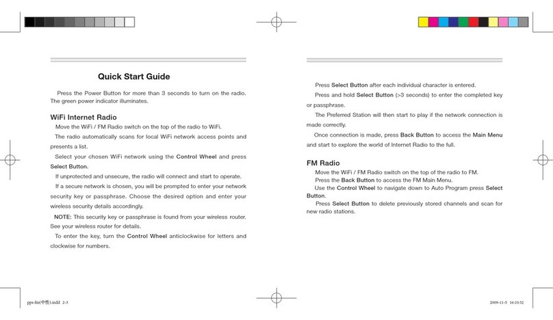
PREPARING YOUR RADIO FOR USE
Attaching/removing the antenna
Attaching / removing the battery pack
1. To att ach, carefully align the antenna with the
socket. Screw in the antenna and clockwise
(taking care not to cross the thread) until it
is seated fi rmly with the ac cessory cover’s
rubber ring between the antenna and the top
of the radio (A).
2.To remove, unscrew the antenna
anti-clockwise (B).
1. To attach, loc ate the pegs on the bottom of the
battery into the slots on the radio and press
the top of the battery against the radio. Secure
battery by tightening the screw clockwise
by hand. (Do not use any implement or over
tighten). (C)
2.To remove, unscrew the locking screw
anti- clockwise and pull the batter y away
from th e top of the radio. (D)
A
B
C
D
SWITCHING ON, RECEPTION
AND SWITCHING OFF
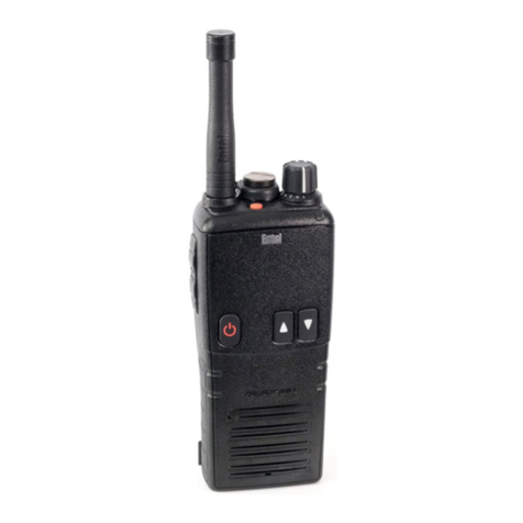
1. To switch on, press and hold the on/of f
button (1) on the f ront of the radio.
2.W he n th e radio has passed its diagno st ic test s,
it will emit a fanfare tone.
3.The radio will enter standby mode. This is
indicated by the LED Amber fl ashing once
every 5 seconds, signaling that the radio is
ready for use.
4.Adjust the volume control (2) to select the
desired volume level.
5. Using the channel buttons (3) ensure you have
the correct channel selected.
6.W hen receiving a valid signal, the LED will
illuminate steady green and audio will be
emitted from the radio’s speaker or audio
accessory (if attac hed).
7. When fi nished using the radio, switc h off
by pressing and holding the on/of f button
(1) until the radio beeps and the LED/LCD is
extinguished.
TRANSMITTING
1. Perform steps 1 through to 5 above.
2.Before transmitting, monitor the channel
and make sure it is clea r.
3.When receiving a signal, wait until the signal
stops before transmitting. The radio cannot
transmit and receive simultaneously.
4.P re ss th e Pu s h To Ta lk (P T T) bu t to n (4) to be gi n
your transmission. To confi rm transmission the
LED illuminates red.
5. For best transmitted speech quality, you must
talk directly into the radio’s microphone (9) at
around 4cm between your m outh and t he radio
complete, the charger.
6.Please note: if you talk into the top of the
radio or with your mouth furt her away, you will
transmit poor quality speech.
7. When the transmission is fi nished release the
PTT button.
DECLARATION OF CONFORMITY
Hereby, Ente l UK Limited of:
320 Centennial Ave, C entennial Park,
Elstree, WD6 3TJ, Unite d Kingdom:
Decla res that th e radio type HT500 Series
is compliant wit h
EN60 945:20 08 / COR1:20 08
Directive 2014/34/EU
HT500 Series
IECEx S IR 10.0097X
HT5X X marking Ex II 2G Ex ib IIA T4 Gb
Sira Certifi cation. Unit 6, Hawarden Industrial
Park, H awarden Deeside, CH5 3US. UK .
Notifi ed Body No. 0518
Quality Assurance Notifi cation:
Intertek. Intertek House, Leatherhead
KT22 7SB, UK
Notifi ed Body No. 0359
Name: Mi ke Jamieso n
Position: Quality Manager
Date: 1st Feb ruary 2 018
Signature:
www.entel.co.uk
All Rig hts Reser ved. Copyr ight Entel UK L td.
Quick Start User Guide V1.0
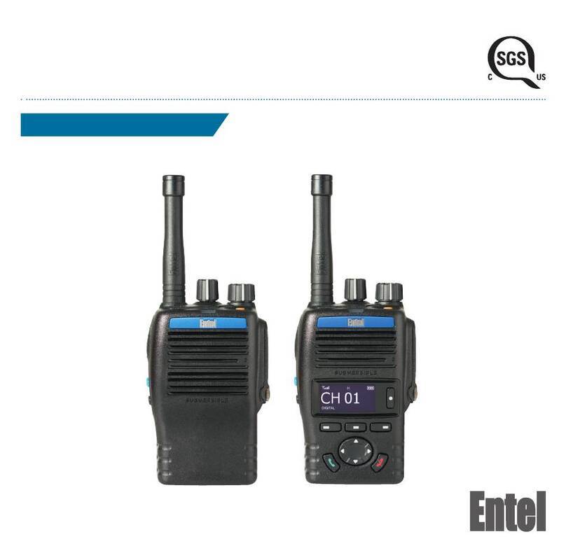
HT544
INTRODUCTION
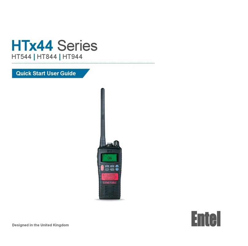
Th e Entel HTx4 4 se ri es are a ran ge of pr of essiona l IP 68 sub me rs ib le m ar ine
han dhe ld ra dio s tha t ope rat e on th e VH F mar ine band . They have 56 marine
international channels and 36 dealer programmable private c hannels.
This quick guide provides basic guidance for op erating your radio.
A f ull version of this user guide is available to download from our website:
www.entel.co.uk.
To meet your exact requirements, the radio may have been customise d
by your Entel dealer. These features will be explained in a separate guide
issued by the deal er.
PACK ING LIST
HTx44 Marine VHF radio
CNBx xx Rechargeable Li -Ion battery
CBH9 50 Spring loaded belt c lip
CCAHT Trick le charg er pod
CAT40 Hi gh effi ciency antenna
CWCHT Mains adaptor
ASPACKCAHV3 Bulkhead screw and spacer kit
OPTIONAL ACCESSORIES
Attaching and removing accessories
1. To attach an accessory, remove the accessory cover by unscrewing the
locking screw anti-clockwise (leave the cover
attached or store in a safe place).
2. Plug the accessory into the socket, then
carefully tighten the locking screw clockwise
until fi nger tight (do not over tighten or use any
implement).
3.To remove an acc essor y, unscrew the locking
screw of the ac cessory by hand in an anti-
clockwise direction.
4.Ensure you re-fi t the accessory socket cover
(the radio is not submersible without the socket
covered).
BAT TERY I NFOR MATI ON
Battery charging
1. Connect the AC adapter to the charger pod and plug in.
2.Turn the radio of f.
3.Insert the batter y pack into the charger pod either with or without the
radio attached. The charger LED status light changes to red and c harging
begins.
4.W hen charging is complete, the charger status LED changes from red
to g reen (a fully discharged battery pack will take approximately 6 hour s
to recharge).
CAUTION
BATTERY PACK PRECAUTIONS
• Do not recharge the battery pack if it is already fully charged. Doing so
may reduce the life of the bat tery pack.
• After charging is com plete, rem ove the bat tery from the charger.
• Please ensure that the radio is turned off before placing it in the charger
and never switch a radio on whilst in the charger.
• Only use Entel br anded bat tery packs and chargers.
• Do not short t he battery terminals or di spose of the battery in a fi re.
• Do not charge the radio and/or battery pac k if they are wet.
DANGER
DO NOT DISASSEMBLE OR MODIFY THE BATTERY IN ANY WAY!
Your Entel battery pack incorporates a safety circuit to avoid danger, if the
safety circuit is damaged or bypassed, or the battery cells are damaged
directly, they may generate extreme heat, smoke, rupture and emit fl ames.
Above approvals apply to specifi c models only
