Entel HT820 User manual

HT820/880
VHF/UHF submersible transceivers
OWNERS MANUAL
Submersible
Dependable
Tough
Class I,ll &lll
Groups A TO G
DIV l&ll T4
INTRINSICALLY SAFE
CLASSES I, II & III
GROUPS A TO G. DIV I & II T4
WARNING:
SUBSTITUTION OF COMPONENTS MAY
IMPAIR INTRINSIC SAFETY
USE DNLY WITH ENTEL BATTERY CNB840E
DO NOT CHARGE OR RECHARGE BATTERY
IN HAZARDOUS LOCATIONS
V/01

CE COMPLIANCE STATEMENT
The HT800 series transceiver displays "CE" on the serial number label,
indicating its compliance with the essential requirements of the EEC directive
for Electromagnetic Compatibility.
DECLARATION OF CONFORMITY
We Entel UK Limited,
OF:
4 Elstree Gate, Elstree Way,
Borehamwood, Herts.
WD6 1JD
United Kingdom
Declare under our sole responsibility that the product:-
HT800 series VHF/UHF handheld transceiver
Serial Number
To which this declaration relates, is in accordance with directive 95/5/EC and
conforms to the following standard or other nominative documents:-
EN 300 086-2 V1.1.1, EN 301 489-1 V1.5.1:2003, EN 60065:2002
Following provisions of the R&TTE directive.
I SO 9001
REGISTERED FIRM
M. Austin.
Quality Manager
Y

3
1.1 GENERAL FEATURES
1.2 PACKING LIST
1.3 OPTIONS (ACCESSORIES)
1.3.1 ATTACHING AUDIO ACCESSORIES
1.4 CONTROLS AND INDICATORS
1.5 LCD INDICATORS
1.6 RECEPTION
1.7 TRANSMITTING
1.8 ADDITIONAL FEATURES
1.9 VOX (voice operated transmit)
2.0 OPTIONAL TRICKLE CHARGER-model CCA230
2.1 OPTIONAL CHARGER-model CSA640E
2.2 BATTERY INDICATOR
2.3 BATTERY SAFETY
2.4 TROUBLE SHOOTING
2.5 SPECIFICATION (General, receive and transmit)
2.6 SAFETY TRAINING INFORMATION
2.7 NOTES
04
04
05
06
09
10
11
11
12
12
13
13
14
15
16
17
20
22
TABLE OF CONTENTS

4
U.S.T.C Certified intrinsically safe
Heavy duty, commercial grade construction
Submersible / Fully waterproof to JIS7
128 PC programmable channels
All CTCSS & DCS tones
Scan mode
Five programmable buttons
Lithium-lon battery technology
14 hour duty cycle
VOX (voice operated transmit)
Low battery warning bleep
Battery level indicator
Extensive range of accessories
XU
YU
ZU
[U
\U
]U
^U
_U
`U
XWU
XXU
XYU
XZU
1.1 GENERAL FEATURES
The supplied package: (U.S.T.C Certified, intrinsically safe)
HT820/880
CNB840E
CBH940
CAT20/80
Owners manual
Transceiver
1800mAh rechargeable lithium-lon battery pack
Spring loaded rear clip
High efficiency antenna
1.2 PACKING LIST

5
The HT800 is supported by a wide range of essential accessories.
For an up to date list visit our web site at www.entel.co.uk
CSA640E
CSB640E
CST640E
CCA230
CCA12
CNB840E
CMP840
EA19/840
EA15/840
EA12/840
CHP1/840
EPT40/840
CHP800/HD
CHP800/HS
CHP800D
CXR5/840
CXR16/840
CLC940
CAT40IS
CBH940
Single pod intelligent rapid charger, 110/230v operation
Six pod intelligent rapid charger, 110/230v operation
3 or 6 pod battery conditioner/analyser
230v drop in trickle charger. (Also available as 110v -CCA110)
12v drop in trickle charger
7.4V 1800mAh rechargeable lithium-Ion battery pack, with rear clip
Submersible, noise cancelling speaker microphone (heavy duty)
Earpiece microphone with PTT button
Covert style ear/microphone with transparent acoustic tube
D Shape earpiece microphone with in-line PTT
Single earpiece headset with in-line PTT(vox)
Bone conductive earpiece microphone
Heavy duty double ear defender for hardhat with PTT (vox)
Heavy duty single ear defender for hardhat and PTT (vox)
Heavy duty double ear defender with headband and PTT (vox)
Skull microphone (vox)
Throat microphone (vox)
Heavy duty leather case with belt loop & carry strap
Flexible antenna
Spring loaded rear clip
1.3 OPTIONAL ACCESSORIES (U.S.T.C Certified)
Accessories suitable for vox operation have been marked (vox)
NOTE: DO NOT CHARGE OR REMOVE THE BATTERY PACK IN
THE HAZARDOUS AREA LOCATION.
NOTE: THE USE OF NON ENTEL APPROVED ACCESSORIES WILL
INVALIDATE YOUR U.S.T.C INTRINSICALLY SAFE APPROVAL

6
Locate accessory connector cover marked "ACC" Lift cover and
rotate (screw) the connector clockwise.
1.3.1 ATTACHING AUDIO ACCESSORIES
1. Attaching the belt clip; Align the belt clip with the plastic
slots of the battery pack. Slide the belt clip downwards onto
the battery pack, pushing firmly until a click is heard.
2. BATTERY REMOVAL/ATTACHMENT
Preparation prior to use
Figure 1. Attachment the accessory connector
1.
Turn the transceiver off.
2. Using a coin, rotate the battery screw anti-clockwise 2 or 3 turns.
**Ensure that you do not hold the battery pack when
unscrewing the release screw!
Note: The accessory socket is waterproof
without the ACC cover in place. However, when
not using an audio accessory we strongly
advise keeping the ACC cover firmly pressed in
its recess to prevent foreign objects from getting
into the socket.

7
Figure 2.
Battery removal / Attachment
To remove rotate
the screw
anti-clockwise
3.
To attach the battery, locate
the bottom section of the
battery and press the battery
against the transceiver, then
rotate the battery screw
clockwise.
1.4 CONTROLS AND INDICATORS
POWER SWITCH/VOLUME CONTROL
Powers the transceiver on and off. Adjusts volume to
desired level.
PUSH TO TALK SWITCH
Hold down to transmit, release to receive.
UP/DOWN button
Select the desired channel by pressing the UP/DOWN buttons.
For fast channel selection hold down for more than 1 second.
LAMP/LOCK button
P1, P2, P3, P4 buttons
Dealer programmable.
button
Dealer programmable.
1.
2.
3.
4.
5.
6.

8
MON buttons
Dealer programmable.
ANTENNA CONNECTOR
Connects the supplied flexible antenna or an optional external
aerial adaptor.
BATTERY PACK
Rechargeable lithium-lon battery packs.
ACCESSORY CONNECTOR
To connect any HT800 Series radio to an Entel approved
audio accessory.
7.
8.
9.
10.

Figure 3. CONTROLS & INDICATORS
ྙPOWER SWITCH
ྚPTT
ྛUP/DOWN
ྞ
ྟMON
ྜLAMP/LOCK
ྠANTENNA CONNECTOR
ྡBATTERY PACK
ྡྷACCESSORY CONNECTOR
ྜྷDEALER
PROGRAMMABLE
(FUNCTION)
INTRINSICALLY SAFE
CLASSES I, II & III
GROUPSATOG. DIVI&IIT4
WARNING:
SUBSTITUTION OF COMPONENTS MAY
IMPAIR INTRINSIC SAFETY
USE DNLY WITH ENTEL BATTERY CNB840E
DO NOT CHARGE OR RECHARGE BATTERY
IN HAZARDOUS LOCATIONS
10
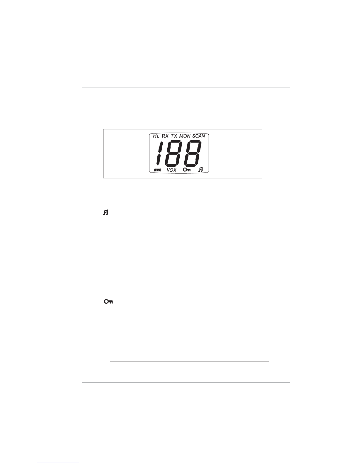
CHANNEL DISPLAY
The operating channel.
Appears when bleep sound is turned on.
H/L
H indicates high power L indicates low power.
SCAN
Appearswhenscanisactivated.
TX
Indicates transmission in progress.
RX
Indicates reception is in progress.
VOX
Voice operated mode enabled.
The keypad is locked.
BATTERY LIFE INDICATOR
The lithium-lon battery of your transceiver is continually
monitored for your convenience and safety.
MON
Monitor button, to open the squelch.
1.5 LCD INDICATORS
Figure 4. LCD indications

11
1.7 TRANSMISSION
1. Perform steps 1 through 3 of RECEPTION.
2. Before transmitting, monitor the channel and make sure it is
clear.
3. When receiving a signal, wait until the signal stops before
transmitting. The transceiver cannot transmit and receive
simultaneously.
4. Press the [PTT] (push-to-talk) switch to begin your transmission.
To confirm transmission in progress the LED illuminates RED, and
TX is displayed on the LCD.
5. Holding the transceiver 1 inch from your mouth speak slowly
and clearly into the microphone.
6. When the transmission is finished, release the [PTT] switch.
1. Turn the transceiver on by rotating the volume control in a
clockwise direction. A power on tone is generated after 1
second to indicate the transceiver has passed its
self-diagnostic test. Select the desired audio level by further
rotating the control clockwise. After power on, the transceiver
will always default to the last channel selected.
2. Select the desired channel using the [UP/DOWN] buttons.
3. When receiving a signal the LED indicator illuminates green,
and "RX" is displayed on the LCD.
1.6 RECEPTION

12
1.8 Additional features
The HT800 Series incorporates some additional features that can be
of positive benefit to your organisation. These features can be set-up
and accessed in a number of different ways using any one of the
programmable buttons. Please contact your dealer to discuss your
exact requirements.
1.9 VOX Voice operated transmit
Any one of the programmable buttons can be assigned to
access the VOX feature.
In VOX mode the transceiver will react to your voice and
transmit automatically without you having to press the PTT
button.
There is always a slight delay for the electronic switching, and
consideration will need to be given.
To get optimum performance from the VOX feature you should
use a noise cancelling headset or earpiece microphone
(see accessory options marked VOX)

2.0 OPTIONAL TRICKLE CHARGER-model CCA230
1. Connect the CWC640 AC
adaptor to the CCA230
charger pod. The LED
status light will illuminate
green indicating ready for
charge.
2. Turn the transceiver off.
3. Insert the battery pack
into the CCA230 pod, either with or
without the transceiver attached. The LED status light changes
from green to RED and trickle charge begins.
4. A fully discharged battery pack will take approximately 6 hours
to charge, depending on the remaining power condition. When
charge is complete, the LED status light turns green.
NOTE: The CWC640 AC adaptor can be replaced by the CMC640
12v charger cable. Charge time remains at 6 hours.
Figure 5. CCA230 Charger pod
kjXY}G
w
X
wY
w
Z
w
[
2.1 OPTIONAL CHARGER-model CSA640E
1. Connect the CSA640E to a
mains supply(110 to 230V).
When switching on the
LED flashes orange briefly
to confirm self-diagnostic
test complete.
w
X
wY
w
Z
w
[
Figure 5-1.
OPTIONAL CSA640E
Rapid charger
110-230VAC

14
2. Turn the transceiver off.
3. Insert the battery pack into the CSA640E charger, either with
or without the transceiver attached. The LED will illuminate red
to indicate rapid charge in progress.
4. Charge time for a fully discharged battery pack will take up to
120 minutes. On completion the LED turns green.
2.2 BATTERY INDICATOR
For your safety and convenience your transceiver continually
monitors the battery pack and gives an indication on the LCD:
3 Segments : 14hours
2 Segments : 1hour
1 Segment : 20mins
Figure 6. Battery Indicator

15
Lithium-Ion battery packs must be recycled or disposed of
properly. For requirements in your area, check with the dealer
from whom you purchased your transceiver.
DO NOT INCINERATE
Do not dispose of your CNB840E battery in a fire or incinerator.
The heat of fire may cause battery cells to explode and/or
release dangerous gases.
DO NOT SHORT BATTERY PACK TERMINALS
Shorting the terminals that power the transceiver can cause sparks,
severe over heating, burns, and battery cell damage.
If the short is of sufficient duration, it is possible to melt the battery
components. Do not place a loose battery pack on or near a
metal surface or objects such as paper clips, keys, tools etc.
When the battery pack is installed on the transceiver, the terminals
that transfer current to the transceiver are not exposed.
The terminals that are exposed on the battery pack when it is
mounted on the transceiver are charging terminals only and do
not constitute a hazard.
DISPOSE OF BATTERY PACKS PROPERLY
2.3 BATTERY SAFETY
The battery pack of your transceiver contains lithium-Ion cells.
This type of battery stores a charge powerful enough to be
dangerous if misused or abused, especially when removed from
the transceiver. Please observe the following precautions:

16
TROUBLESHOOTING CHART
SYMPTOM
Transceiver not
switching on
Battery needs charging
Battery is exhausted
Charge the battery pack
Replace the battery pack
REMEDYPROBABLE CAUSE
2.4 TROUBLE SHOOTING
Cannot change any
function
Key lock is switched on Turn key lock off
LED on CCA640 & CWC640
does not illuminate when
charging
Defective battery,
CCA640, or CWC640
Dirty terminal contact
on CCA640
Contact your dealer
Clean contacts with dry
clean cloth
Receiving calls from other
users outside your radio
system
congestion on channel contact your dealer for new
frequency or sub tone
assignment
Transceiver transmits
without pressing PTT button
Buttons seem to work
intermittently
VOX has been enabled Press assigned vox button to
switch vox off.

128ch
148-170MHz(VHF)/438-470(UHF)MHz
22MHz(VHF)/30MHz(UHF)
25KHz
12.5KHz
5KHz/6.25KHz
59 x 33 x 130mm
296g
7.4V, Nominal
50mA, Max.
160mA, Max.
1,000mA, Max.
1,800mA, Max.
50 ohms
8 ohms
·2.5ppm Max.
-20to +50
2.5 SPECIFICATION(General, receive and transmit)
Performance specifications are nominal, unless otherwise
indicated, and are subject to change without notice.
GENERAL
Number of Channels
Frequency Range
Operational Bandwidth
Channel Spacing - Wide Band
Narrow Band
Channel Increments
Size (WxDxH)
Weight (With Battery and Antenna)
Battery Voltage
Current Drain
Squelched (w/out Power Saver)
Rated Audio
Transmit-1 watt
Transmit-5 watts(4 watts UHF)
Antenna impedance
Speaker impedance
Frequency Stability
Operation Temperature
17

Sensitivity (12dB SINAD)
Squelch Sensitivity
Adjacent Channel Selectivity (ETS)-Wide Band
Narrow Band
Spurious Rejection (ETS)
Intermodulation (ETS)
Hum and Noise Ratio-Wide Band
Narrow Band
Rated Audio Output at 5% T.H.D.(1KHz)
GGGGGGGGGGGGGGGGGGGGeWUZ\}GtU
GGGGGGGGGGGGGGGGGGGeXWiGzpuhk
GGGGGGGGGGGGGGGGGGGGGGGGGGGGGGGGGGGGGGGGGGGG^WiGtU
GGGGGGGGGGGGGGGGGGT]WiGt
GGGGGGGGGGGGGGGT^WiGtU
GGGGGGGGGGGGGGGT]\iGtU
GGGGGGGGGGGT[\iGtU
GGGGGGGGGGGGGGGGGGGGGGGGGGGT[WiGtU
GGGGGGGGGGGGG\WW~G{
RECEIVER
5W(VHF)/4W(UHF)
1W(VHF)/1W(UHF)
-36dBm<1GHz
-30dBm>1GHz
·5KHz
·2.5KHz
-40dB Typical
5% Max.
-70dB
-60dB
TRANSMITTER
RF Output Power-Hi Power
Low Power
Spurious/Harmonic Emissions
Modulation-Wide Band
Narrow Band
FM Hum and Noise
Audio Distortion
Adjacent Channel Power-Wide Band
Lo Power
X_

19
Certification
USTC Certified
Intrinsically Safe
Classes I, ll & lll
GROUPSATOG.DIVI&IIT4
ඖThe
HT820/880
must always be used within the terms of its certification
ඖKeep
HT820/880
away from aggresive substances. If used in a hostile
environment, extra protection may be needed.
ඖTo prevent ignition of hazardous atmospheres, batteries must only
be charged or changed in an area known to be non hazardous.
ඖNo unauthorised repairs are permitted. Details of authorised service
centres are available from Entel UK.

20
FOR USA VERSION:-
2.6 SAFETY TRAINING INFORMATION
WARNING.
Your Entel radio generates RF electromagnetic energy during transmit
mode. This radio is designed for and classified as "Occupational Use Only",
meaning it must be used only during the course of employment by
individuals aware of the hazards, and the ways to minimize such hazards.
This radio is NOT intended for use by the "General Population" in an
uncontrolled environment.
Use only Entel approved accessories. Use of accessories other than those
specified may result in RF exposure levels exceeding the FCC requirements
for wireless RF exposure.
CAUTION.
To ensure that your exposure to RF electromagnetic energy is within the
FCC allowable limits for occupational use, always adhere to the following
guidelines:-
ඖDO NOT operate the radio without a proper antenna attached, as this
may damage the radio and may also cause you to exceed FCC RF
exposure limits. A proper antenna is the antenna supplied with this radio
by the manufacturer or antenna specifically authorized by the manufacturer
for use with this radio.
ඖDO NOT transmit for more than 50% of total radio use time
("50% duty cycle"). Transmitting more than 50% of the time can cause
FCC RF exposure compliance requirements to be exceeded.
The radio is transmitting when the "TX indicator" lights red.
You can cause the radio to transmit by pressing the "PTT" switch.
This manual suits for next models
1
Table of contents
Other Entel Radio manuals

Entel
Entel HT981 Installation guide

Entel
Entel HT 44 Series Setup guide

Entel
Entel DX Digital Series Setup guide

Entel
Entel HT981 Reference guide

Entel
Entel DX482M Setup guide

Entel
Entel DX446L Setup guide

Entel
Entel HT446E Installation instructions

Entel
Entel HT544 Setup guide

Entel
Entel DX Marine Series Setup guide

Entel
Entel HT446E/L User manual


