Policyl
Procedure
LONDON
FIRE
BRIGADE
Entel
HT981
fireground
radio
and
savox
interface
equipment
(BARIE)-training
note
Official
New
policy
number:
516
Old
instruction
number:
TRN:EO15:a1
Issue
date:
12
July
2007
Reviewed
as
current:
22
November
2016
Owner:
Head
of
Operational
Policy
Responsible
work
team:
Incident
Communications
Contents
1
Aims
.......................................................................................................................................................................
2
2
Objectives
.............................................................................................................................................................
2
3
Introduction
..........................................................................................................................................................
2
4
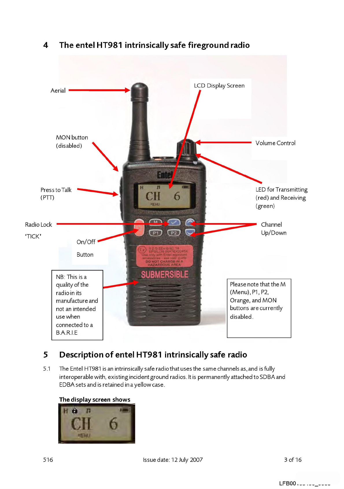
The
entel
HT981
intrinsically
safe
fireground
radio
......................................................................................
5
Description
of
entel
HT981
intrinsically
safe
radio
.......................................................................................
:3
6
The
savox
interface
equipment
connected
toentel
HT981
in
yellow
case
..............................................
6
7
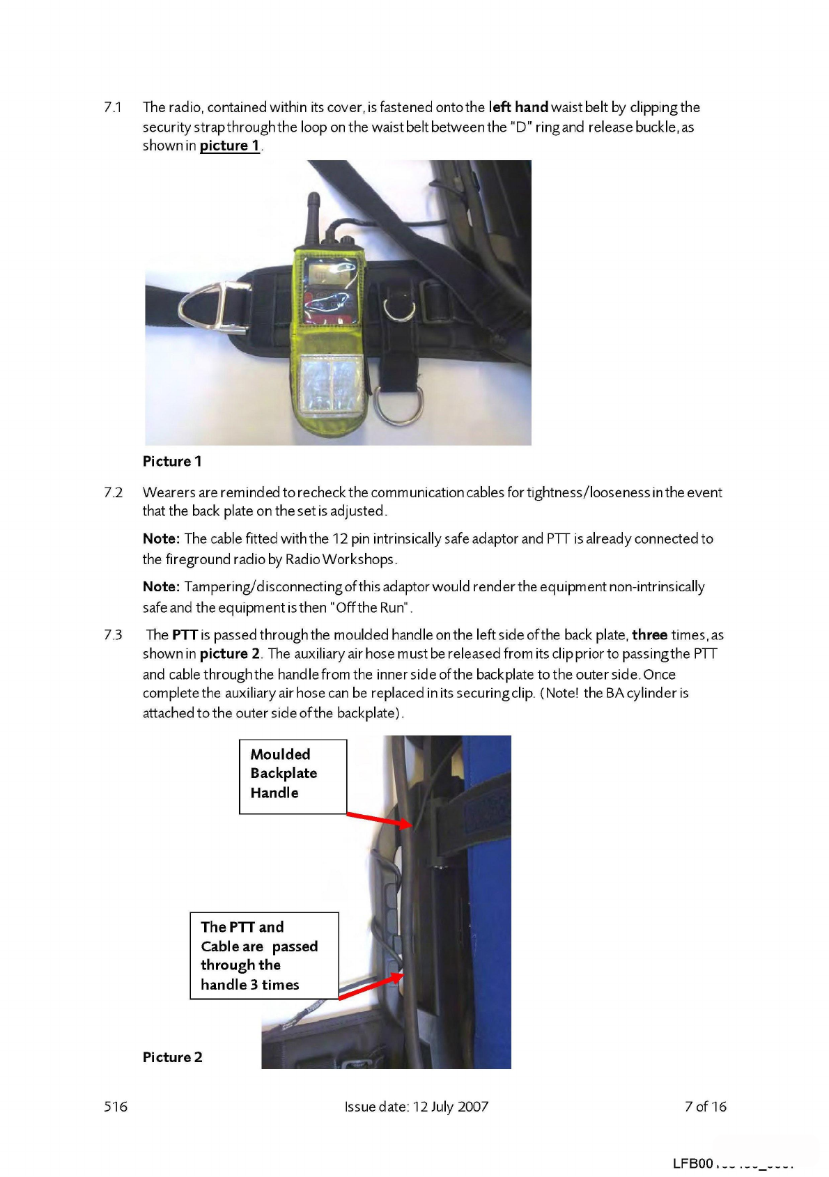
Fitting
B.A.R.I.E.
to
a
breathing
apparatus
set
...............................................................................................
6
8
Operational
use
..................................................................................................................................................
12
9
Channels
..............................................................................................................................................................
12
10
Battery
fitting,
removal
and
charging
............................................................................................................
13
11
Cleaning,
testing
and
recording
.....................................................................................................................
14
12
Testing
.................................................................................................................................................................
14
Document
history
..............................................................................................................................
16
Review
date:
22
November
2019
516
Issue
date:
12
July
2007
Last
amended
date:
1
of
16
LFBO0105450
0001
LFB00105450/1