How to Use This Guide
UsethisguidetoquicklysetupyourEnterasys®SecureStack™C3
switch.EnterasysNetworksrecommendsthatyourefertothe
EnterasysSecureStackC3HardwareInstallationGuideassociated
withyourswitchforspecificationsandsafetywarnings.
Thelatestdocumentationislocatedat
www.enterasys.com/support/manuals.
Hardware Components
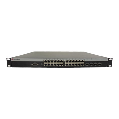
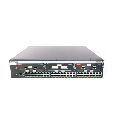
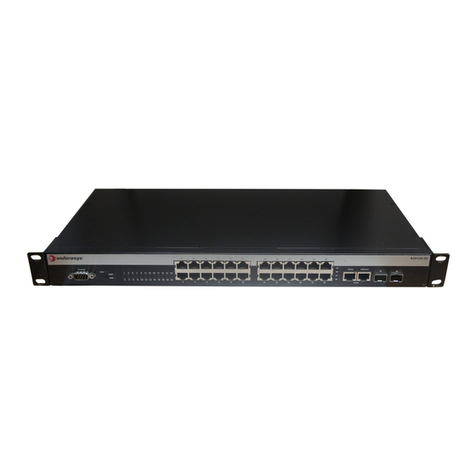
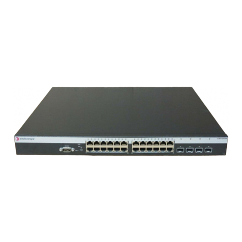
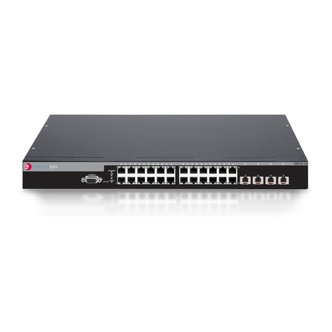
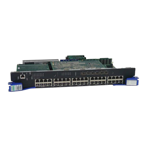
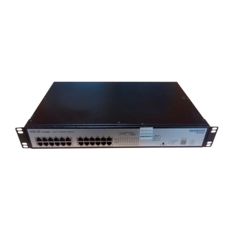
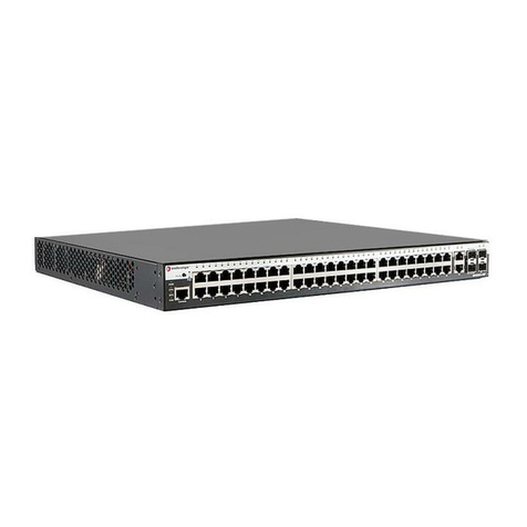
Thefollowingfiguresshowtheseveraltypesoffrontpanelport
andrearpanelconnectionsonyourC3switch.
Figure 1 C3G124-24, C3G124-24P
Figure 2 C3G124-48, C3G124-48P
Figure 3 C3K122-24, C3K122-24P (shown with C3K-2XFP IOM)
Figure 4 C3K172-24 (shown with C3K-2XFP IOM)
Figure 5 C3 Switch Rear (C3K122-24 Displayed)
Figure 6 C3K-2XFP IOM
Key
1DB9 RS232 Console Port Connector
2Switch Status LEDs
3RJ45 10/100/1000 Mbps Ports
4SFP Slots
5XFP Slots
6RJ45 Port Status LEDs
7SFP Port Status LEDs
8XFP Port Status LEDs
9C3K-2XFP IOM (optional)
10 Password Reset Button
11 Stack Connection Ports
12 AC Power Input Connector
13 Redundant Power Supply (RPS) DC Connector
Handling the Switch
Topreventelectrostaticdamage,attachanelectrostaticdischarge
(ESD)wriststraptoyourwristbeforehandlingtheswitch.
Unpacking the Switch
Unpacktheswitchasfollows:
1. Removethepackingmaterialprotectingtheswitch.
2. Removethetapesealonthenon‐conductivebagtoremovethe
switch.
3. Performavisualinspectionoftheswitchforanysignsof
physicaldamage.ContactEnterasysNetworksifthereareany
signsofdamage.See“GettingHelp”formoreinformationon
contactingEnterasysNetworks.
Installing the C3K-2XFP IOM
1. Removethecoverplatethatconcealstheexpansionslotby
looseningitstwocaptivescrews.
2. Withyourantistaticwriststrapattached,gentlyinsertthe
C3K‐2XFPIOMintotheswitchguiderails(asdisplayedin
Figure 7)untiltheIOMengagestheconnectoronthebackplane
andthemodulelocksintoplace.
3. TightenthecaptivescrewsonthefrontoftheC3K‐2XFPIOM.
Figure 7 Installing the C3K-2XFP IOM
Connecting Power to the Switch
Youcanconnecttoasingle,primarysourceofpower,ortotwo
sourcesofpowerforredundancy.Theexampleusedheredescribes
connectingtotwopowersources.
Thefollowingredundantpowersuppliesareavailabletobe
purchasedfromEnterasysNetworksforconnectiontoaC3switch:
•C2RPS‐PSM,a102‐156wattDCpowersupplycapableof
providingpowertoafully‐loadednon‐PoEswitch.
•C2RPS‐POE(C3K122‐24P,C3G124‐24P,andC3G124‐48Ponly),
500wattDCpowersupplyrecommendedforfullPoEcapability.
Topower‐upyourC3switch:
1. Attachthepowercordfromyourredundantpowersupplyinto
theC3switch’sredundantpowerreceptacle.
Caution: The switch can be damaged by electrostatic discharge.
Note: The C3K-2XFP IOM is installed in C3K switches labeled with
a -G and is an optional add-on for all other C3K switches.
1IOM Guide Rails
Electrical Hazard: Only qualified personnel should perform
installation procedures.
Note: Enterasys Networks recommends installing any components
before powering on your switch.
2. AttachtheACpowercordtotheC3switch’sACpower
receptacle.
3. PlugtheredundantpowersupplyandtheC3switchAC
powercordintodedicated,groundedACoutlets.
4. Oncepowerisconnected,verifythattheRPSpowerLEDturns
green,andtheCPU(system)LEDturnsamberuntiltheC3
switchfinishesitsinitialization.
5. Iftheinitializationprocessissuccessful,theCPULEDturns
green.IftheCPULEDdoesnotturngreen,refertothe
EnterasysSecureStackC3HardwareInstallationGuideassociated
withyourC3switchfortroubleshootinginformation.
Completing Switch Setup and Downloading the Latest
Firmware
OnceyouhaveconnectedpowertotheC3switchandverified
LEDactivity,youcancompletethesetupprocessasfollows.Refer
totheEnterasysSecureStackC3HardwareInstallationGuide
associatedwithyourC3switchformoreinformation.
1. DeterminethelatestC3firmwareversionbyvisitingthe
EnterasysNetworksdownloadsiteat:
http://secure.enterasys.com/services/support/downloads/software
2. Connecttheswitchtothenetwork.
3. Connectamanagementstationtotheconsoleport.
4. Verifythatthenetworkdevicesconnectedtotheswitchports
arepoweredon,andthateachlink/activityLEDison(solid
greenorblinkinggreen).
5. Atthedeviceconnectedtotheconsoleport,performthe
following:
a. EnteradminforUsername.
b. AtthePasswordprompt,pressENTER(RETURN).
c. Atthecommandprompt,determineifthelatestfirmware
imageisloadedontheswitchbyenteringthiscommand:
show version
d.Iftheoutput(underFWVer si o n)displaysanolderversion
numberthanthatdeterminedinStep1,downloadand
activatethenewversionasdirectedonthedownloadwebsite.
(Alternatively,youcanusetheCLIcommandlistedin
Table 1.)
Basic Setup Commands
Table 1listsCLIcommandsthatarerequiredforsettinguptheC3
switchwiththelatestfirmware.Table 2listsadditional
configurationcommandsforyourC3switch.Forthecompletelist
ofCLIcommands,seetheEnterasysSecureStackC3Configuration
Guide.
Table 1 Required CLI Setup Commands
Step Ta s k CLI commands
1Set a new password set password [username]
2Set the switch IP address set ip address ip-address [mask
ip-mask] [gateway ip-gateway]
3Download, activate, and
verify new firmware on the
switch using TFTP copy
Note: You can reboot the
system immediately with the
set boot system command,
or reboot later with the reset
command.
copy
tftp://tftp_server_ip_address/
filename system:image
set boot system filename
show version
Specifications
Foracompletelistofspecifications,seetheEnterasysSecureStack
C3HardwareInstallationGuideassociatedwithyourC3switch.
Interfaces
C3G124‐24andC3G124‐24P
•Fourcombo1000Base‐SX,or1000Base‐LXSFPports
•Twenty‐four10BASE‐T/100BASE‐TX/1000BASE‐Tports
C3G124‐48andC3G124‐48P
•Fourcombo1000Base‐SX,or1000Base‐LXSFPports
•Forty‐eight10BASE‐T/100BASE‐TX/1000BASE‐Tports
C3K122‐24andC3K122‐24P
•Fourcombo1000Base‐SX,1000Base‐LX,or100Base‐FXSFP
ports
•Twenty‐four10BASE‐T/100BASE‐TX/1000BASE‐Tports
C3K172‐24
•Twenty‐four1000Base‐SX,1000Base‐LX,or100Base‐FXSFP
ports
C3K‐2XFP
•Two10‐GigabitSmallFormFactorPluggable(XFP)interfaces
Switch Dimensions
Size:354.40x441x44.0mm
Power Consumption
InputVoltage:100to240VAC
Temperature and Humidity
Operating:C3switches:0ºCto50ºC
Storage:‐40ºCto+70ºC
Operatingrelativehumidity:5%to95%
Table 2 Optional CLI Setup Commands
Task CLI commands
Save the active configuration save config
Enable or disable SSH set ssh enable | disable
Enable or disable Telnet set telnet {enable | disable}
[inbound | outbound | all]
Enable or disable HTTP
management (WebView)
set webview {enable | disable}
Enable or disable SNMP port link
traps
set port trap port-string
{enable | disable}
Set the per port broadcast limit set port broadcast port-string
threshold-value
Configure a VLAN set vlan create vlan-id
set port vlan port-string
vlan-id modify-egress
Set a Syslog server IP and severity set logging server index ip-addr
ip-addr severity severity state
enable
Configure and enable a RADIUS
server
set radius server index ip-addr
port [secret-value]{realm
{management-access | any |
network-access}
set radius enable
Note: The 10BASE-T/100BASE-TX/1000BASE-T ports on the
C3G124-24P, C3G124-48P, and the C3K122-24P also support
802.af PoE connections.
