Entratek Caro Series User manual

User Manual
Caro Series Wallbox

6
3
2
CONTENTS
01
04
External Structure
Product Details
Specification
04
06
08
10
11
2.1
2.2
2.3
10
Safety and Warnings
1
Product Introduction
Installation Details
Maintenance 20
7Warranty 20
03
Package Contents
519
Opening
Mounting
3.1
3.2
4
12
14
15
16
12
Operation and Configuration
Charging Operation - Plug & Charge
Charging Operation - Use RFID Card
Evchargo APP
AP mode
4.1
4.2
4.3
4.4
Troubleshooting
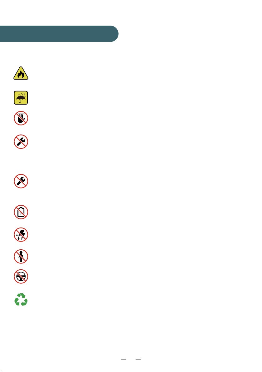
01
Keep the charger away from explosive or flammable materials, chemi-
cals, vapors and other hazardous objects.
Keep the charge point socket clean and dry. If it gets dirty, please wipe
it with a clean, dry cloth.
Do not touch the socket pin when the unit is powered on.
Do not use the charge point if it is showing any visible product damage
such as cracks, abrasions, bare leakage, and other visible defects. At
first sight of such damages, immediately contact a qualified techni-
cian.
Do not attempt to dissemble, repair or refit the charge point. If neces-
sary, please contact the qualified technician. Improper operation will
result in device damage, electric leakage and other hazards.
In case any abnormal condition happens, please turn off incoming
power supplies immediately.
Please consider charge point protection against lightning and heavy
rain.
Keep children away from the charge point.
During charging, do not drive the EV. Charge only when the EV is
stationary. For hybrid cars, charge only when the engine is switched off.
Our packaging materials are environmentally friendly and can be
recycled. Please put the packaging in applicable containers to recycle
it. Do not dispose of this device with the household waste. It should be
taken to a suitable facility for recycling of electrical and electronic
devices. For more detailed information about recycling of this device,
please contact your local city/town council office or your household
waste disposal service.
Save these instructions. Read all instructions before installing or using the
charger.
Safety and Warnings
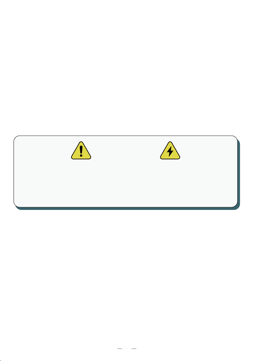
The device can be in electrically energized state. There is risk of shock
and electrical hazard. Please strictly observe all warnings on the
device and user manuals. The cover of the charge point is only to be
removed by a qualified electrician.
Warning
02
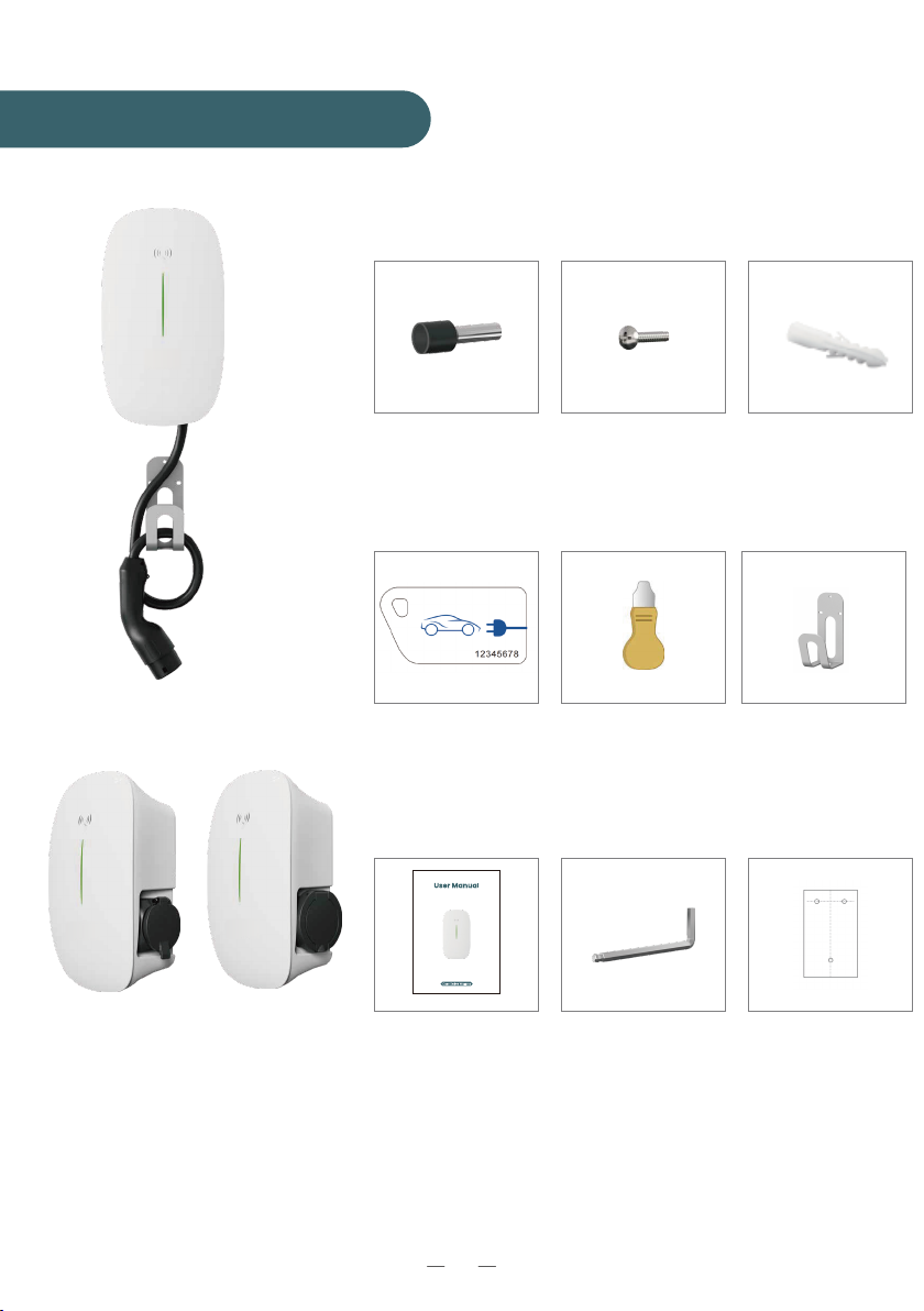
AC Charger (Cable Version)
Mounting
Position Template (*1)
User Manual (*1)
Cable Hook (*1)
(only for cable version)
01/ Package Contents
AC Charger (Socket Version)
Type 2 Socket T2S Socket
RFID Activation Card
(*2)
Insulated Terminal
(*3) for single-phase
(*5) for three-phase
M4 Hex Key (*1)
φ6 Wall Plugs
(*6) for cable version
(*3) for socket version
M4*32 Screw
(*6) for cable version
(*3) for socket version
03
Dismounting Tool (*1)
This manual suits for next models
1
Table of contents
Popular Automobile Accessories manuals by other brands


ULTIMATE SPEED
ULTIMATE SPEED 279746 Assembly and Safety Advice

SSV Works
SSV Works DF-F65 manual

ULTIMATE SPEED
ULTIMATE SPEED CARBON Assembly and Safety Advice

Witter
Witter F174 Fitting instructions

WeatherTech
WeatherTech No-Drill installation instructions

TAUBENREUTHER
TAUBENREUTHER 1-336050 Installation instruction