Entree BCBD1 User manual
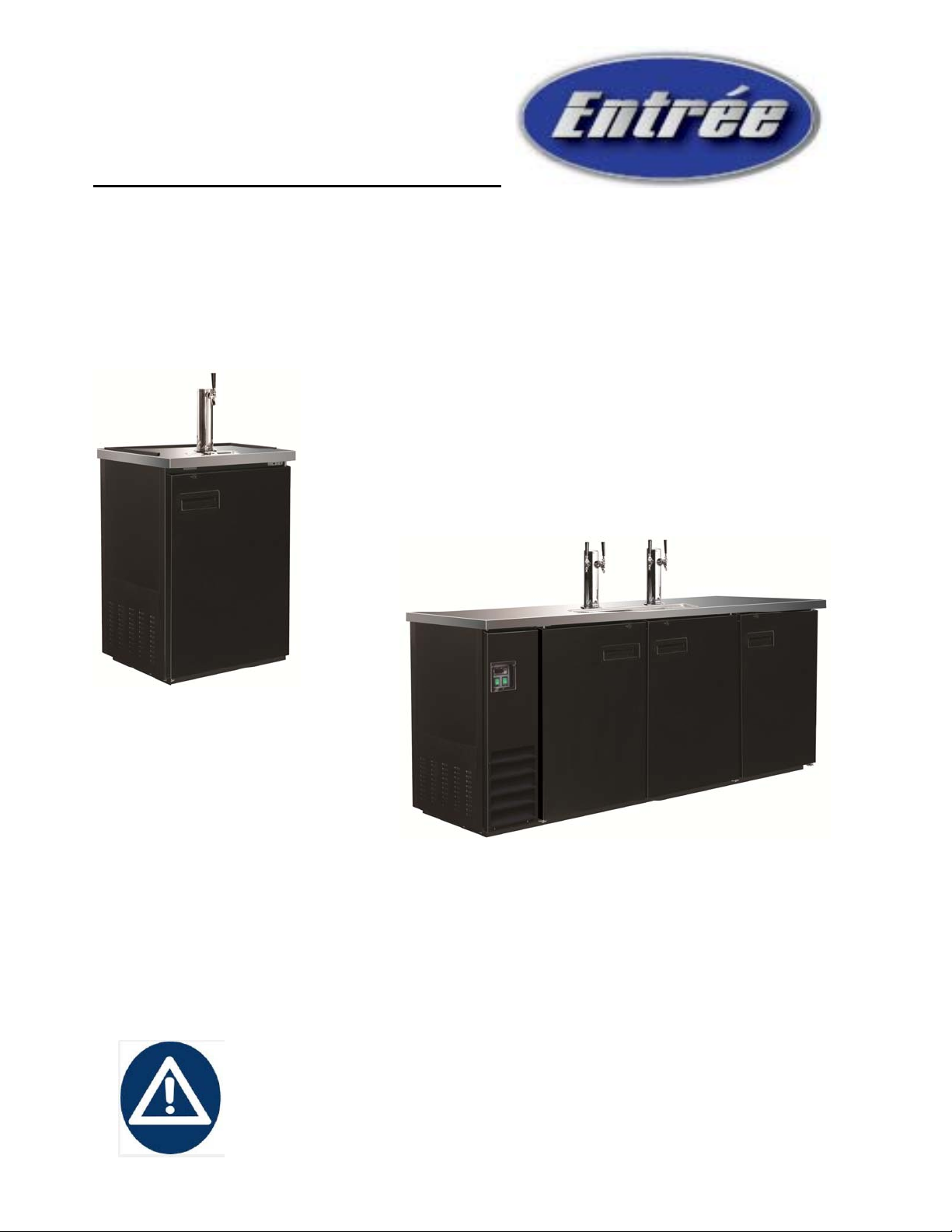
BeerDispensers
Service,InstallationandCareManual
Pleasereadthismanualcompletelybeforeattemptingtoinstalloroperatethisequipment.
Notifycarrierofdamage! Inspectallcomponentsimmediately.
IMPORTANT INFORMATION
READ BEFORE USE
PLEASE SAVE THESE INSTRUCTIONS!
Service and Installation Manual
For warranty service, call 866-417-6140
2
CONTENTS
RECEIVING & INSPECTING EQUIPMENT --------------------------------------------------------- 2
SPECIFICATIONS ----------------------------------------------------------------------------------------- 2
INSTALLATION --------------------------------------------------------------------------------------------- 3
OPERATION ------------------------------------------------------------------------------------------------- 3-4
MAINTENANCE -------------------------------------------------------------------------------------------- 5-6
WARRANTY INFORMATION ---------------------------------------------------------------------------- 10
All rights reserved. Reproduction without written permission is prohibited.
SERIAL NUMBER INFORMATION
The serial number of all self-contained refrigerators and freezers is located inside the unit on the left hand
side near the top on the wall. Always have the serial number of your unit available when calling for parts or
service.
This manual covers standard units only. If you have a custom unit, consult the customer service department
at the number listed on the last page.
RECEIVING AND INSPECTING THE EQUIPMENT
Even though most equipment is shipped crated, care should be taken during unloading so the equipment is
not damaged while being moved into the building.
1. Visually inspect the exterior of the package and skid or container. Any damage should be noted and
reported to the delivering carrier immediately.
2. If damaged, open and inspect the contents with the carrier.
3. In the event that the exterior is not damaged, yet upon opening, there is concealed damage to the
equipment notify the carrier. Notification should be made verbally as well as in written form.
4. Request an inspection by the shipping company of the damaged equipment. This should be done within
10 days from receipt of the equipment.
5. Be certain to check the compressor compartment housing and visually inspect the refrigeration package.
Be sure lines are secure and base is still intact.
6. Freight carriers can supply the necessary damage forms upon request.
7. Retain all crating material until an inspection has been made or waived.
SPECIFICATION
BEER DISPENSERS
MODEL# V/Hz/Ph AMPS
STORAGE
CAPACITY
Cu-ft HP BTU
CHARGE
OZ
SHIP
WEIGHT
LBS
NEMA
PLUG
BCBD1 115/60/1 2.5 7.2 1
/
8740 2.82 161 5-15P
BCBD2-1 115/60/1 3.2 10.45 2
/
51155 8.05 264 5-15P
BCBD2-2 115/60/1 3.2 10.45 2
/
51155 8.05 267 5-15P
BCBD3-1 115/60/1 3.2 14.16 2
/
51155 8.05 302 5-15P
BCBD3-2 115/60/1 3.2 14.16 2
/
51155 8.05 304 5-15P
BCBD4-2 115/60/1 3.5 17.26 1
/
21771 8.05 351 5-15P
Service and Installation Manual
For warranty service, call 866-417-6140
3
INSTALLATION
Location
Units represented in this manual are intended for indoor use only. Be sure the location chosen has a floor
strong enough to support the total weight of the cabinet and contents. A fully loaded unit can weigh as much
as 1500 pounds. Reinforce the floor as necessary to provide for maximum loading. For the most efficient
refrigeration, be sure to provide good air circulation inside and out.
Outside cabinet:
Be sure that the unit has access to ample air. Avoid hot corners and locations near stoves and ovens.
It is recommended that the unit be installed no closer than 2" from any wall with at least 12" of clear space
above the unit. Should it become necessary to lay the unit on its side or back for any reason, allow at least
24 hours before start-up so as to allow compressor oil to flow back to the sump. Failure to meet this
requirement can cause compressor failure and unit damage.
Leveling
A level cabinet looks better and will perform better because the doors will line up with the frames properly,
the cabinet will not be subject to undue strain and the contents of the cabinet will not move around on the
shelves. Use a level to make sure the unit is level from front to back and side to side. Units supplied with
legs will have adjustable bullet feet to make the necessary adjustments. If the unit is supplied with casters,
no adjustments are available. Ensure the floor where the unit is to be located is level.
Stabilizing
Models are supplied on casters for your convenience, ease of cleaning underneath and for mobility. It is very
important, however, that the cabinet be installed in a stable condition with the front wheels locked while in
use.
Standard warranties will be voided due to improper installation procedures.
Electrical connection
Refer to the amperage data on page 3, the serial tag, your local code or the National Electrical Code to be
sure the unit is connected to the proper power source. A protected circuit of the correct voltage and
amperage must be run for connection of the line cord, or permanent connection to the unit.
The ON/OFF switch must be turned to OFF and the unit disconnected from the
power source whenever performing service, maintenance functions or cleaning
the refrigerated area.
OPERATION
Do not throw items into the storage area. Failure to heed these recommendations
could result in damage to the interior of the cabinet.
Refrigerators: The factory setting for temperature range is 34°F - 38°F
On/Off Switch:
An on/off switch is located on the side of the bottom shroud. When the unit is on, the switch will glow
green.
Light Switch:
An light switch is located next to on/off switch on the front of the bottom shroud.

Service and Installation Manual
For warranty service, call 866-417-6140
4
SOLID-STATE THERMOSTAT DESCRIPTIONS
1. FRONT PANEL COMMANDS
1.1 KEY FUNCTION
To display target set point; in programming mode it selects a parameter or confirm an
operation.
To start a manual defrost
To see the last temperature alarm happened; in programming mode it browses the parameter
codes or increases the display value
To see the last temperature alarm happened; in programming mode it browses the parameter
codes or decreases the display value
KEY COMBINATION
To lock & unlock the keyboard
To enter in programming mode
To return to the room temperature display
1.2 Function of LEDS
2. MAIN FUNCTIONS
2.1 HOW TO SEE THE SETPOINT
1. Push and immediately release the SET key: the display will show the set point value;
2. Push and immediately release the SET key or wait for 5 seconds to display the sensor value again.
2.2 HOW TO CHANGE THE SETPOINT
1. Push the SET key for more than 2 seconds to change the set point value;
2. The value of the set point will be displayed and the LED starts blinking;
3. To change the set value push the or key within 10s;
4. To memory the new set point value and push the SET key again or wait 10s.
2.3 HOW TO START A MANUAL DEFFROST
Push the key for more than 2 seconds and a manual defrost will start
2.4 HOW TO LOCK THE KEYBOARD
1. Keep pressed the and keys for more than 3s;
2. The “POF” message will be displayed and the keyboard will be locked. At this point, it will be possible only
to see the set point or the MAX or Min temperature stored;
3. If a key is pressed more than 3s the ”POF” message will be displayed.
2.5 HOW TO UNLOCK THE KEYBOARD
Keep pressed the and keys together for more than 3s, till the “Pon” message display, then press
or key to select the item to check or program.

Service and Installation Manual
For warranty service, call 866-417-6140
5
3. ALARM SIGNALS
HOW TO SEE THE ALARM AND
RESET THE RECORDED ALARM
1. Push the or key, the
alarm signals are displayed;
2. When the signal is displayed, hold
the SET key until the “rst” message
is displayed, and push the SET key
again, the “rst” message start
blinking and the normal temperature
will be displayed again.
MAINTENANCE
The power switch must be turned to OFF and the unit disconnected from the
power source whenever performing service, maintenance functions or cleaning
the refrigerated area.
Refrigerators
The interior and exterior can be cleaned using soap and warm water. If this isn't sufficient, try ammonia and
water or a nonabrasive liquid cleaner. When cleaning the exterior, always rub with the "grain" of the stainless
steel to avoid marring the finish.
Do not use an abrasive cleaner because it will scratch the stainless steel and plastic and can damage the
breaker strips and gaskets.
Cleaning the Condenser Coil
The condenser coil requires regular cleaning, recommended is every 90 days. In some instances, you may
find that there is a large amount of debris and dust or grease accumulated prior to the 90 day time frame. In
these cases the condenser coil should be cleaned every 30 days.
If the build up on the coil consists of only light dust and debris the condenser coil can be cleaned with a
simple brush, heavier dust build up may require a vacuum or even compressed air to blow through the
condenser coil.
If heavy grease is present, there are de-greasing agents available for refrigeration use and specifically for
the condenser coils. The condenser coil may require a spray with the de-greasing agent and then blown
through with compressed air.
Failure to maintain a clean condenser coil can initially cause high temperatures and excessive run times,
continuous operation with dirty or clogged condenser coils can result in compressor failures. Neglecting the
condenser coil cleaning procedures will void any warranties associated with the compressor or cost to
replace the compressor.
Never use a high pressure water wash for this cleaning procedure as water can
damage the electrical components located near or at the condenser coil.
In order to maintain proper refrigeration performance, the condenser fins must be cleaned of dust, dirt and
grease regularly. It is recommended that this be done at least every three months. If conditions are such that
the condenser is totally blocked in three months, the frequency of cleaning should be increased. Clean the
condenser with a vacuum cleaner or stiff brush. If extremely dirty, a commercially available condenser
cleaner may be required.
Service and Installation Manual
For warranty service, call 866-417-6140
6
Stainless Steel Care and Cleaning
To prevent discoloration of rust on stainless steel several important steps need to be taken. First, we need to
understand the properties of stainless steel. Stainless steel contains 70-80% iron which will rust. It also
contains 12-30% chromium which forms an invisible passive film over the steels surface which acts as a
shield against corrosion. As long as the protective layer is intact, the metal is still stainless. If the film is
broken or contaminated, outside elements can begin to breakdown the steel and begin to form rust of
discoloration. Proper cleaning of stainless steel requires soft cloths or plastic scouring pads,
NEVER USE STEEL PADS, WIRE BRUSHES OR SCRAPERS!
Cleaning solutions need to be alkaline based or non-chloride cleaners. Any cleaner containing chlorides
will damage the protective film of the stainless steel. Chlorides are also commonly found in hard water, salts,
and household and industrial cleaners. If cleaners containing chlorides are used be sure to rinse repeatedly
and dry thoroughly upon completion.
Routine cleaning of stainless steel can be done with soap and water. Extreme stains or grease should be
cleaned with a non-abrasive cleaner and plastic scrub pad. It is always good to rub with the grain of the steel.
There are also stainless steel cleaners available which can restore and preserve the finish of the steels
protective layer.
Early signs of stainless steel breakdown can consist of small pits and cracks. If this has begun, clean
thoroughly and start to apply stainless steel cleaners in attempt to restore the passivity of the steel.
Never use an acid based cleaning solution!Many food products have an acidic content
which can deteriorate the finish. Be sure to clean the stainless steel surfaces of ALL food
products. Common items include, tomatoes, peppers and other vegetables.
Gasket Maintenance
Gaskets require regular cleaning to prevent mold and mildew build up and also to keep the elasticity of
the gasket. Gasket cleaning can be done with the use of warm soapy water. Avoid full strength
cleaning products on gaskets as this can cause them to become brittle and prevent proper seals. Also,
never use sharp tools or knives to scrape or clean the gasket which could possibly tear the gasket and
rip the bellows.
Gaskets can easily be replaced and don’t require the use of tools or authorized service persons. The
gaskets are "Dart" style and can be pulled out of the grove in the door and new gaskets can be "pressed"
back into place.
Doors/Hinges
Over time and with heavy use doors the hinges may become loose. If it is noticed that the door is
beginning to sag, it may become necessary to tighten the screws that mount the hinge brackets to the
frame of the unit. If the doors are loose or sagging this can cause the hinge to pull out of the frame which
may damage both the doors and the door hinges. In some cases this can require qualified service
agents or maintenance personnel.
Drain Maintenance
Each unit has a drain located inside the unit which removes the condensation from the evaporator coil and
evaporates it at an external condensate evaporator pan. Each drain can become loose or disconnected from
moving or bumping the drain. If you notice excessive water accumulation on the inside of the unit, be sure
the drain tube is connected from the evaporator housing to the condensate evaporator drain pan. If water is
collected underneath the unit you may want to check the condensate evaporator drain tube to be sure it is
still located inside the drain pan. The leveling of the unit is important as the units are designed to drain
properly when on a level surface, if your floor is not level this can also cause drain problems. Be sure all
drain lines are free of obstructions typically food product is found blocking drain lines causing water to back
up and overflow the drain pans.
Service and Installation Manual
For warranty service, call 866-417-6140
7
MAINTENANCE
Swing Door Replacement and Adjustment
1. Open the bottom shroud and hold the door, then loose bottom hinge’s screws and take off the old door;
2. Prepare new door, insert top pin into top hinge, get one bottom hinge to hold the door by the bottom pin ,
then fasten bottom hinge securely to the door frame with three screws;
3. Allow the door to freely swing, make sure it swing close by itself with no restriction;
4. Plug the unit in and make sure the lock work well;
5. If not, adjust the door height by adding the plastic spacer/washer provided to the bottom hinge pin.
DIRECT DRAW DRAFT ARM INSTALLATION
On direct draws, the drain is located at the front of the cabinet. To plumb in the drain, connect P.V.C. pipe to
the barbed fitting supplies with the unit.
INSTALLING C02 CYLINDER AND REGULATOR
Make certain that all fittings in system are tight. Always keep the CO2 cylinder in vertical position.
The recommended pressure for the CO2 system is 8-10 psi.
Handle all pressure system components with care. Do not use excessive pressures. Be sure
instructions are understood thoroughly. If in doubt, contact your dealer/distributor for
explanation.
Filled CO2 tanks are potentially dangerous because of the pressure they contain. If you are
unfamiliar with their use or the use of the CO2 regulator, seek information from your local
distributor, or your local beverage man before proceeding.
Service and Installation Manual
For warranty service, call 866-417-6140
8
MAINTENANCE
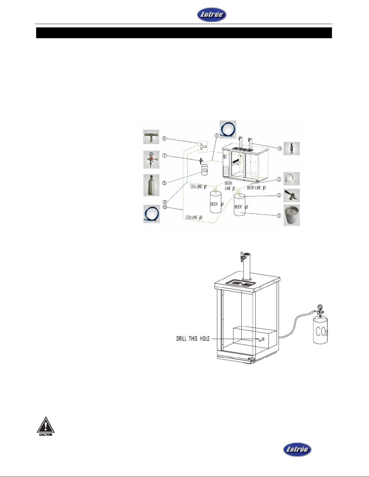
INSTALL DRAFT ARM AND PARTS LIST
Place rubber washer over draft arm mounting holes in cabinet, put beer line connector down through hole.
Next, secure draft arm with four screws.
Insert air hose (one inch plastic tube) in draft arm, being careful not to disturb insulation. Remove top cover
of draft arm and attach air hose clip to the insulating sleeve at the top of the draft arm. Replace top cover.
The air hose clip will assure that the hose remains in proper place at all times, keeping the beer faucet cold.
1. Beer Keg
2. “D” Sharp Keg Tap
3. Beer Line
4. Beer Dispenser
5. CO2 Line
6. CO2 Tee Joint
7. CO2 Regulator
8. CO2 Cylinder
9. CO2 Line#1
10. CO2 Line#2
ONE DOOR CO2 KNOCK-OUT
This instruction is the procedure for installing a remote CO2 container for one door unit.
REQUIRED TOOLS
• Pliers
• Power Drill
• Silicone Sealer
• Drill bit, 1/2”
STEP 1 - Remove black knockout plug with a pair of pliers.
NOTE: Knockout plug for CO2 line can be locate in two different areas.
View diagram to locate these two areas.
STEP 2 - Use drill and bit to bore hole straight back through wall into compressor compartment.
STEP 3 - Snake CO2 line through hole down and around exiting behind rear castor underneath rear grill.
STEP 4 - Seal hole around CO2 line with silicone sealer to prevent cold air leakage.
Don't lay CO2 cylinders flat.
Don't drop CO2 cylinders.
Service and Installation Manual
For warranty service, call 866-417-6140
9
TWO-YEARPARTS&LABORWARRANTY
(For products produced after serial number 1301ENTH00001)
ENTRÉE L.L.C. warrants to the original purchaser of every new refrigerated unit, the cabinet and all parts thereof,
to be free from defects in material or workmanship, under normal and proper use and maintenance service as
specified by ENTRÉE LLC and upon proper installation in accordance with the Owner’s Manual supplied with
each Entrée L.L.C. unit. Entrée L.L.C. obligation under this warranty is limited to a period of two (2) years from
the date of original purchase or thirty 30 months after shipment date from Entree, whichever occurs first. Any
model of refrigeration equipment installed in a non-permanent structure, such as a mobile kitchen and/or trailer
shall have a thirty (30) days limited warranty from the date of purchase. Proof of purchase required.
Any part covered under this warranty that is determined by Entrée to have been defective within two (2) years of
original purchase or thirty (30) months after shipment date from manufacturer, whichever occurs first, is limited to
the repair or replacement, including labor charges, of defective parts or assemblies. The labor warranty shall
include standard straight time labor charges only and the established flat rate trip charges.
Warranty does not cover standard wear parts which include door gaskets, incandescent bulbs or fluorescent
bulbs, loosened fasteners of door or lid hinges. Warranty also does not cover issues caused by improper
installation or lack of basic preventative maintenance which includes regular cleaning of condenser coils.
ADDITIONAL THREE-YEAR COMPRESSOR WARRANTY
In addition to the Two (2) year warranty stated above, Entrée L.L.C. warrants its hermetically sealed compressor
to be free from defects in both material and workmanship under normal and proper use and maintenance service
for a period of three (3) additional years from the date of original installation but not to exceed five (5) years and
three (3) months after shipment from the manufacturer. Removal or defacement of the original Serial Number or
Model Number from any Unit shall be deemed to release Entree from all obligations hereunder or any other
obligations, express or implied.
IF THE CUSTOMER IS USING A PART THAT RESULTS IN A VOIDED WARRANTY AND AN ENTREE
AUTHORIZED REPRESENTATIVE TRAVELS TO THE INSTALLATION ADDRESS TO PERFORM WARRANTY
SERVICE, THE SERVICE REPRESENTATIVE WILL ADVISE CUSTOMER THE WARRANTY IS VOID. SUCH
SERVICE CALLS WILL BE BILLED TO CUSTOMER AT THE AUTHORIZED SERVICE CENTER'S THEN
APPLICABLE TIME AND MATERIALS RATES.
If shipment of a replacement part is requested by the end user prior to the arrival in the Entree factory of the part
claimed to be defective, the Original Purchaser must accept delivery of the replacement part of a C.O.D. basis,
with credit being issued after the part has been received and inspected at Entree's plant and determined by
Entree to be within this warranty.
Compressors determined by Entrée L.L.C. to have been defective within this extended time period will, at Entrée
L.L.C. option, be either repaired or replaced with a compressor or compressor parts of similar design and capacity.
The freight charges for sending a replacement compressor are not covered by this warranty. Replacement of a
defective Compressor is limited to one (1) Compressor by us during the three years period.
The three (3) year extended compressor warranty applies only to hermetically sealed parts of the compressor
and does not apply to any other parts or components, including, but not limited to: cabinet, paint finish,
temperature control, refrigerant, metering device, driers, motor starting equipment, fan assembly or any other
electrical component, etcetera.

Service and Installation Manual
For warranty service, call 866-417-6140
10
TWO-YEARPARTS&LABORWARRANTY
(For products produced after serial number 1301ENTH00001)
404A/134A COMPRESSOR WARRANTY
The compressor warranty detailed above will be voided if the following procedure is not carefully adhered to:
1. If the refrigerator/freezer does not cool within 1 hour/60 minutes, turn the unit off and call for service. If the
refrigeration system is void of Freon and the compressor is allowed to run more than an hour damage will occur
to the compressor and will cause it to fail. Failure/replacement of the compressor in this manner is not covered by
this warranty.
2. Drier replacement is very important and must be changed when a system is opened for servicing. The new
drier must also be the same capacity as the drier being replaced.
3. Micron level vacuums must be achieved to insure low moisture levels in the system. 500 microns or lower
must be obtained.
WARRANTY CLAIMS
All requests for must be called into 866-417-6140 to obtain and agree to service dispatch with Warranty Claim
Payment Terms. All claims for labor or parts must be made directly through Entrée L.L.C.
All claims should include: Dispatch number, model number of the unit, the serial number of the cabinet, proof of
purchase, date of installation, and all pertinent information supporting the existence of the alleged defect.
In case of warranty compressor, the compressor warranty form must be filled out by a qualified refrigeration
technician. This form can be obtain by down load from our website: www.entree.biz. This form must be emailed,
in its completion, with a copy of the original proof of purchase to: john@entree.biz.
WHAT IS NOT COVERED BY THIS WARRANTY
Entrée L.L.C. sole obligation under this warranty is limited to either repair or replacement of parts, subject to the
additional limitations below. This warranty neither assumes nor authorizes any person to assume obligations
other than those expressly covered by this warranty. Travel beyond 50 miles round trip and more than 2 hours
round trip.
NO CONSEQUENTIAL DAMAGES. ENTRÉE L.L.C. IS NOT RESPONSIBLE FOR ECONOMIC LOSS; PROFIT
LOSS; OR SPECIAL, INDIRECT, OR CONSEQUENTIAL DAMAGES, INCLUDING WITHOUT LIMITATION,
LOSSES OR DAMAGES ARISING FROM FOOD OR PRODUCT SPOILAGE CLAIMS WHETHER OR NOT ON
ACCOUNT OF REFRIGERATION FAILURE.
WARRANTY IS NOT TRANSFERABLE. This warranty is not assignable and applies only in favor of the original
purchaser/user to whom delivered. ANY SUCH ASSIGNMENT OR TRANSFER SHALL VOID THE
WARRANTIES HEREIN MADE AND SHALL VOID ALL WARRANTIES, EXPRESS OR IMPLIED, INCLUDING
ANY WARRANTY OF MERCHANTABILITY OR FITNESS FOR A PARTICULAR PURPOSE.
IMPROPER USAGE. ENTRÉE L.L.C. ASSUMES NO LIABILITY FOR PARTS OR LABOR COVERAGE FOR
COMPONENT FAILURE OR OTHER DAMAGES RESULTING FROM IMPROPER USAGE OR INSTALLATION
OR FAILURE TO CLEAN AND/OR MAINTAIN PRODUCT AS SET FORTH IN THE OWNER’S MANUAL
PROVIDED WITH THE UNIT.
TWO-YEARPARTS&LABORWARRANTY

Service and Installation Manual
For warranty service, call 866-417-6140
11
(For products produced after serial number 1301ENTH00001)
RELOCATION OF CABINET FOR REPAIR: Entrée L.L.C. is not responsible for the cost to move a cabinet for
any reason from its position of operation on the customer's premises to make a warranty repair.
RESIDENTIAL APPLICATIONS: Entrée L.L.C. assumes no liability for parts or labor coverage for component
failure or other damages resulting from installation in non-commercial or residential applications.
ALTERATION, NEGLECT, ABUSE, MISUSE, ACCIDENT, DAMAGE DURING TRANSIT OR INSTALLATION,
FIRE, FLOOD, ACTS OF GOD. Entrée L.L.C. is
not responsible for the repair or replacement of any parts that Entrée L.L.C. determines have been subjected
after the date of manufacture to alteration, neglect, abuse, misuse, accident, damage during transit or installation,
fire, flood, or act of God.
IMPROPER ELECTRICAL CONNECTIONS. ENTRÉE L.L.C. IS NOT RESPONSIBLE FOR THE REPAIR OR
REPLACEMENT OF FAILED OR DAMAGED COMPONENTS RESULTING FROM INCORRECT SUPPLY
VOLTAGE, THE USE OF EXTENSION CORDS, LOW VOLTAGE, OR UNSTABLE SUPPLY VOLTAGE. THE
USE OF PIERCING VALVES IS PROHIBITED AND IF LEFT IN THE SYSTEM VOIDS ALL WARRANTIES.THIS
EQUIPMENT IS INTENDED FOR INDOOR USE ONLY.
NO IMPLIED WARRANTY OF MERCHANTABILITY OR FITNESS FOR A PARTICULAR PURPOSE: THERE
ARE NO OTHER WARRANTIES, EXPRESSED, IMPLIED OR STATUTORY, EXCEPT THE TWO (2) YEAR
PARTS & LABOR WARRANTY AND THE ADDITIONAL THREE (3) YEAR COMPRESSOR WARRANTY AS
DESCRIBED ABOVE. THESE WARRANTIES ARE EXCLUSIVE AND IN LIEU OF ALL OTHER WARRANTIES,
INCLUDING IMPLIED WARRANTY AND MERCHANTABILITY OR FITNESS FOR A PARTICULAR PURPOSE.
THERE ARE NO WARRANTIES WHICH EXTEND BEYOND THE DESCRIPTION ON THE FACE HEREOF.
OUTSIDE U.S.: This warranty does not apply to, and Entrée L.L.C. is not responsible for, any warranty claims
made on products sold or used outside the United States and Canada.

Service and Installation Manual
For warranty service, call 866-417-6140
12
ENTRÉE LLC
4673 OSBORNE DR., SUITE I
EL PASO, TX 79922
Technical Support 570-752-4602
www.entree.biz
This manual suits for next models
5


