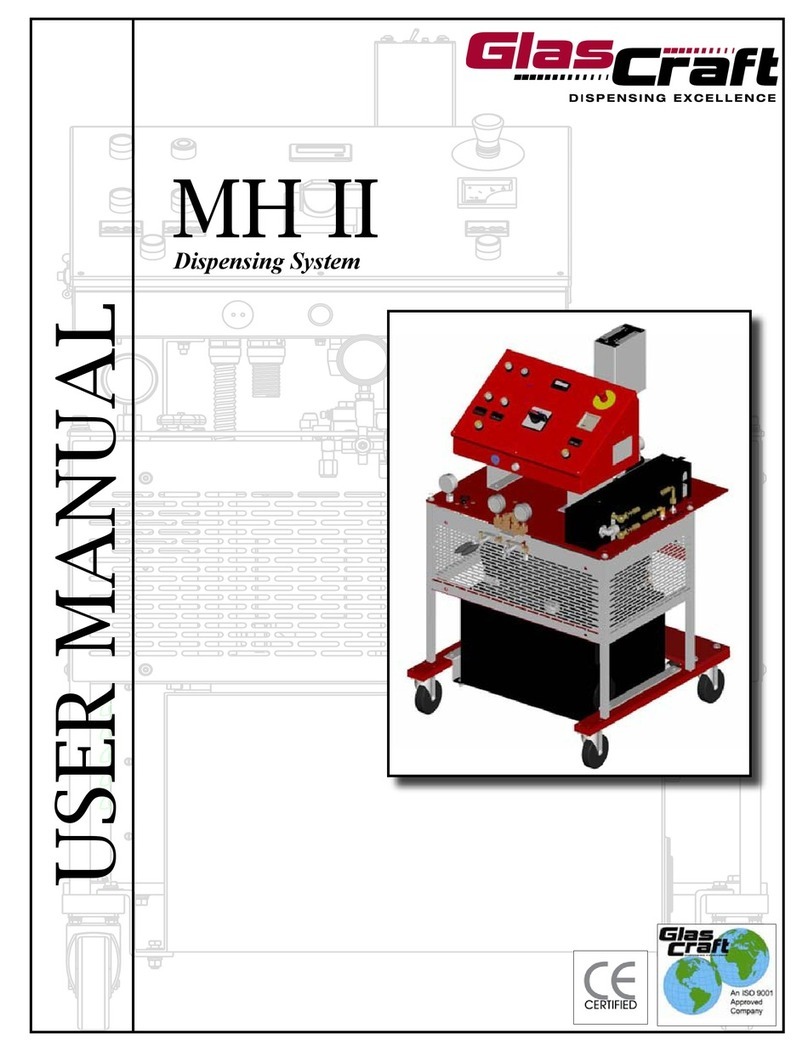
Glas Craft MH II User manual

5845 WEST 82ND STREET
INDIANAPOLIS, INDIANA
46278 U.S.A.
Phone (317) 875-5592
Fax (317) 875-5456
Email [email protected]
Web www.glascraft.com
MH II
Dispensing System
USER MANUAL

Introduction
About This Manual.................................................................................................................................................... 1
Parts & Illustrations
MH II System List / Options / Repair Parts Kits ....................................................................................................... 2
System Specifications .............................................................................................................................................. 3
22850-XX MH II System Console ............................................................................................................................. 4
22850-XX MH II System Assembly ........................................................................................................................... 6
22852-XX MH II Control Box Assembly .................................................................................................................... 15
22852-XX MH II Schematic ...................................................................................................................................... 20
22852-01 MH II Schematic ...................................................................................................................................... 22
21835-00 Fluid Section Assembly ........................................................................................................................... 25
22075-00 Heat Exchanger Assembly ...................................................................................................................... 27
19524-01 Medium Pressure Hose Assembly .......................................................................................................... 31
Typical System Layout ............................................................................................................................................. 32
Typical System Hose Connections For 50 Ft. .......................................................................................................... 33
Typical System Connections For 100-300 Ft. .......................................................................................................... 34
Safety
Urethane Safe Handling and Use of Foam Equipment ............................................................................................ 35
Installation
Instructions ............................................................................................................................................................... 39
Optional Transfer Pump Installation / Air Dryer Kit .................................................................................................. 41
Electrical Connections .............................................................................................................................................. 42
Hydraulic Pack ......................................................................................................................................................... 42
Operation
Initial Start-up Procedures ........................................................................................................................................ 43
Over Pressure System Protection ............................................................................................................................ 46
Over Pressure Problem Correction .......................................................................................................................... 47
System Shut Down ................................................................................................................................................... 48
System Daily Start-Up ............................................................................................................................................... 49
Limited Warranty Policy ................................................................................................................................ 51
Notes ..................................................................................................................................................................... 52
If You Have An Equipment Problem ......................................................................................................... 56
For Your Reference .................................................................................................... INSIDE BACK COVER
Table Of Contents

Introduction
About This Manual
Before operating, maintaining or servicing any
GlasCraft system, read and understand all of the
technical and safety literature provided with GlasCraft
products. If you do not have the proper or related
manuals and safety literature for your GlasCraft sys-
tem, contact your GlasCraft distributor or GlasCraft,
Inc.
In this GlasCraft technical and safety publication, the
following advisories will be provided where
appropriate:
NOTE
Is information about the procedure in progress.
CAUTION
Is imperative information about equipment
protection.
WARNING
Is imperative information about personal safety.
The information in this document is intended only to
indicate the components and their normal working
relationship typical use. Each assembly should be
directed by a GlasCraft distributor or
made from the GlasCraft assembly instructions pro-
vided.
This manual provides information for the assembly,
operation, maintenance and service of this GlasCraft
product as used in a typical configuration. While it
lists standard specifications and procedures, some
deviations may be found.
In order to provide our users with the most up-to-date
technology possible, we are constantly seeking to im-
prove products. If technological change occurs after
a product is on the market, we will implement that
technology in future production and, if practical, make
it available to current users as a retrofit, up-date or
supplement. If you find some discrepancy between
your unit and the available documentation, contact
your GlasCraft distributor to resolve the difference.
GlasCraft, Inc. reserves the right to change or modify
this product as it deems necessary.
Careful study and continued use of this manual will
provide a better understanding of the equipment and
process, resulting in more efficient operation, longer
trouble-free service and faster, easier troubleshoot-
ing.
1

Parts & Illustrations
MH II Dispensing System
25lbs.(12kg.)/min. Spray or Pour Dispensing System
Includes
22850-XX MH II Dispensing System
17254-XX Probler Gun Assembly • W/ Round Spray Mixing Chamber
18006-01 Whip Hose Assembly
19524-01 Medium Pressure Heated Hose Assembly
17661-XX Gun Service Kit
59934-04 Dioctyl Phthalate, 1 Qt.
GC-1267 System User Manual
Options
22023-01 High Pressure Hose Assy., 50 Ft.
19524-01 Medium Pressure Hose Assy., 50 Ft.
22094-00 Required To Complete Hose Electrical Circuit
when used with 18006-00 whip hose.
Recommended Service Kits
17661-XX Gun Service Kit
21063-00 Heat Exchanger Kit
21845-00 Pump Fluid Section Repair Kit
2

System Specifications
Material Ratio: 1:1 (Fixed)
Material Viscosity: 200- 2000 Centipoise (Cps)
At Operating Temperatures
Output: .021 GPS
.042 GPC
Operating Temperatures: 32º F ( 0º C ) - 190º (88 º C )
Operating Psi: 3000 Psi. Max (Over Psi Switches Set)
Hoses: 2200 PSI. W/ 19524-01
2600 PSI. W/ 22024-01
Hydraulic Psi To Pumps: 2:1 Ratio
1000 PSI. Hydraulic PSI.
2000 PSI. Fluid PSI. Per Side.
Purging: Automatic Pneumatic, Solvent-free, Constant
Electrical Requirements: 74 Amps @ 208/240 Vac, 50/60 Hz Single Phase 5 HP
35 Amps @ 208/240 Vac, 50/60 Hz Three Phase 5 HP
27 Amps @ 380 Vac, 50 Hz Three Phase 5 HP
Compressed Air Requirements: 15 Cfm @ 100 Psi
425 Liters @ 6.8 Bar
Max Hose Length: 310’ X 3/8 I.d. Hose
Includes 10’ X ¼ I.d. Heated Whip Hose
Shipping Weight: 950 Lbs
Overall Dimensions:
3

22850-XX MH System Console
4

22850-XX MH System Console
1 MAIN POWER SWITCH
Controls power and door; handle must point 1 to
energize power , handle must point to 0 to open control
box door. White pilot indicates when lighted, that the
main power is on.
2EMERGENCY STOP PUSH
BUTTON
To stop all functions, push down on red button. To reset,
turn handle on push button. All functions will remain off
until main power switch has been switched off and back
on
3 AMMETER An instrument for measuring amperes to the primary
side of the hose’s transformer.
4HOSE TEMPERATURE
CONTROLLER
Controls temperature of liquid inside the heated hoses.
To set desired temperature, press the up or down button
until you reach desired temperature From this point, the
temperature control is completely automatic.
5 ON PUSH BUTTON Powers the controller. It requires 10 seconds for the
Controller to respond.
6 WHITE PILOT LIGHT Indicates power on.
7 POLY PRESSURE GAUGE Indicates material pressure.
8 ISO PRESSURE GAUGE Indicates material pressure.
9 HYDRAULIC PRESSURE KNOB
Increases or decreases hydraulic pressure. Turn
clockwise to increase pressure. Turn counter-clockwise
to decrease pressure.
10 HYDRAULIC PRESSURE GAUGE Indicates hydraulic pump pressure
11 ON PUSH BUTTON Powers the controller. It requires 10 seconds for the
Controller to respond.
12 ISO / POLY TEMPERATURE
CONTROLLER
Controls temperature of liquid inside ISO heater. To set
desired temperature, press the up or down button until
you reach desired temperature. From this point, the
temperature control is completely automatic.
13 OVER-PRESSURE RESET
BUTTONS
When over-pressure is detected, the hydraulic power
pack will be shut down, and will remain off until
pressure is reduced and the push button is reset.
14 ON PUSH BUTTON Power On To the hydraulic power pack.
15 OFF PUSH BUTTON Power Off to the hydraulic power pack.
16 COUNTER Counts pumps cycles.
.042 GPC / .021 GPS
17 RETRACT SWITCH Retracts pumps to the full down stroke position to
protect pump shafts.
18 HYDRAULIC OIL FILL CAP Remove cap to fill tank with recommended hydraulic oil.
19 ISO / POLY DUMP VALVES Relieves pressure and material from ISO & POLY side.
20 HOSE THERMOCOUPLE OUTLET Power outlet for hose thermocouple.
5

22850-XX MH II System Assembly
REVISION P
6

22850-XX MH II System Assembly
REVISION P
7
*
* NOTE: Use the 22145-05 power pack
with 22850-01.

22850-XX MH II System Assembly
REVISION P
8

22850-XX MH II System Assembly
REVISION P
9

22850-XX MH II System Assembly
REVISION P
10

22850-XX MH II System Assembly
REVISION P
11

22850-XX MH II System Assembly
REVISION P
12

13
22850-XX MH II System Assembly Parts List
PART
NUMBER DESCRIPTION
21819-00 LIVE WIRE DECAL
21835-00 PUMP ASSEMBLY
21847-00 CE PLATE
21881-00 PRESSURE GAUGE
21884-02 MATERIAL HOSE
22074-00 THERMOCOUPLE ASSEMBLY
22075-00 HEAT EXCHANGER ASSEMBLY
22083-00 RUN DECAL
22084-00 RETRACT DECAL
22088-05 ISO ELECTRIC PLUG ASSEMBLY
22088-06 POLY ELECTRIC PLUG ASSEMBLY
22105-00 (ISO) HEAT EXCHANGER ASSEMBLY
22101-00 ROLLER LIMIT SWITCH
22106-01 BULKHEAD FITTING
22107-02 ELBOW FITTING
22110-00 (POLY) HEAT EXCHANGER ASSEMBLY
22115-01 UPPER SHAFT CAM ADAPTER
22118-00 ISOLATION HOSE MOUNTING BLOCK
22123-00 CHANGEOVER STAND-OFF
22124-00 BOTTOM PUMP BRACKET
22125-00 MOUNTING PLATE
22126-00 SIDE FRAME SUPPORT
22127-00 VERTICAL FRAME SUPPORT
22128-00 FRONT FRAME SUPPORT
22132-00 BOTTOM CHANGEOVER PLATE
22133-00 TOP CHANGEOVER PLATE
22139-00 LIMIT SWITCH MOUNTING BRACKET
22145-03 HYDRAULIC MOTOR
22155-00 DECAL HYDRAULIC PRESSURE
22156-01 TEE FITTING
22160-01 CAP
22161-00 ROTATION DECAL
22164-00 DIRECTIONAL CONTROL VALVE
22167-00 FRONT HYDRAULIC MOTOR COVER
22169-00 SIDE HYDRAULIC MOTOR COVER
22172-00 COUNTER CHANGEOVER GUARD
22173-00 HYDRAULIC PUMP SUPPORT BRACKET
22175-03 MATERIAL HOSE
22175-04 MATERIAL HOSE
22175-05 MATERIAL HOSE
22177-01 MATERIAL HOSE
22212-02 BULKHEAD FITTING
22297-00 CONNECTION NOTICE DECAL
22543-00 SWIVEL FITTING
PART
NUMBER DESCRIPTION
RM-856-04 ELBOW FITTING
RS-118 ISO DECAL
RS-119 POLY DECAL
10009-04 ELBOW FITTING
10009-06 ELBOW FITTING
10009-07 ELBOW FITTING
10599-40F SET SCREW
13424-03 CABLE TIE
14638-04 RIVET
17597-01 CONNECTOR FITTING
18012-01 HEATED HOSE COVER
18428-01 NEEDLE VALVE
18468-03 FITTING
19507-04 AIR HOSE ASSEMBLY
19616-00 SWIVEL CASTER
19858-00 AIR MOTOR STAND-OFF
19859-00 PUMP MOUNTING PLATE
19861-00 PUMP SADDLE
19984-00 AIR MOTOR STAND-OFF
20188-20C SCREW
20188-28C SCREW
20639-03 GAUGE
20732-03 TUBING
20735-01 ELBOW FITTING
20735-04 ELBOW FITTING
20750-03 SWIVEL TEE FITTING
20796-01 FITTING
20796-02 FITTING
20849-01 UNION BULKHEAD FITTING
21094-01 ELBOW FITTING
21119-00 TRANSFORMER
21129-00 TRANSFORMER DECAL
21308-40C MACHINE SCREW
21315-00 CONNECTOR FITTING
21323-00 FLEXIBLE CONDUIT
21327-01 ELBOW FITTING
21390-01 AIR MOTOR STAND-OFF
21613-80C SET SCREW
21660-00 2-WAY CONTROL VALVE
21806-00 LEFT GUARD
21807-00 RIGHT GUARD
21809-05 MATERIAL HOSE
21809-06 MATERIAL HOSE
21809-07 MATERIAL HOSE
REVISION P

14
22850-XX MH II System Assembly Parts List
PART
NUMBER DESCRIPTION
7966-10 PIPE FITTING
7966-17 PIPE FITTING
8155-40C SCREW
8155-80C SCREW
8156-32C SCREW
8301-24C SCREW
8301-40C SCREW
8560-03 CONNECTOR FITTING
8560-05 CONNECTOR FITTING
8560-11 CONNECTOR FITTING
8560-17 CONNECTOR FITTING
8846-03 COPPER WIRE
9704-03 TUBING
9944-40C SCREW
9945-32C SCREW
9955-40C SCREW
9955-64C SCREW
9955-72C SCREW
PART
NUMBER DESCRIPTION
22706-16 SCREW
22707-00 TRANSFORMER COVER
22716-02 HOLE PLUG
22851-00 BOTTOM BRACKET
22852-XX CONTROL BOX ASSEMBLY
22853-00 CONTROL BOX SUPPORT
22854-00 MOUNTING PLATE
22855-02 MATERIAL HOSE
22856-00 MOUNTING PLATE
22859-00 HYDRAULIC CYLINDER
22861-00 REAR GUARD
23411-00 ELBOW FITTING
3795-00 TERMINAL RING LUG
3923-02 SPIRAL WRAP
4342-23 TEE PIPE FITTING
5307-02 CONDUIT NUT
6782-23 TEE FITTING
7208-02 WIRE NUT
7208-04 WIRE NUT
7486-04 FLAT WASHER
7486-05 FLAT WASHER
7486-07 FLAT WASHER
7486-08 FLAT WASHER
7486-10 LOCK WASHER
7486-13 FLAT WASHER
7486-14 FLAT WASHER
7486-27 FLAT WASHER
7729-10 NUT
7733-06 NUT
7733-12 NUT
7733-14 NUT
7733-17 NUT
7733-34 NUT
7733-42 NUT
7734-03 LOCK WASHER
7734-06 LOCK WASHER
7734-07 LOCK WASHER
7734-10 LOCK WASHER
7734-12 LOCK WASHER
7735-40C SCREW
7957-40C SCREW
7958-32C SCREW
7957-32F SCREW
7957-40F SCREW
7959-20C SCREW REVISION P

22852-XX MH II Control Box Assembly
REVISION N
15

22852-XX MH II Control Box Assembly
REVISION N
16

22852-XX MH II Control Box Assembly
REVISION N
17

22852-XX MH II Control Box Assembly
REVISION N
18
Other manuals for MH II
1
Table of contents
Other Glas Craft Dispenser manuals

Glas Craft
Glas Craft Probler P2 User manual

Glas Craft
Glas Craft Probler User manual

Glas Craft
Glas Craft GCP3RA User manual

Glas Craft
Glas Craft Auto Probler P2 User manual

Glas Craft
Glas Craft GUARDIAN A5-3000 IP User manual

Glas Craft
Glas Craft MH II User manual

Glas Craft
Glas Craft Guardian A6-6000 IP User manual

Glas Craft
Glas Craft GUARDIAN User manual

Glas Craft
Glas Craft Guardian A5-6000 IP User manual