5IP1936 • 2010-08-25
FR DE
ALLGEMEINE SICHERHEITSHINWEISE
Das vorliegende Installationshandbuch ist ausschliesslich für
Fachpersonal bestimmt. Vor Einbaubeginn sind die Anweisungen
sorgfältig durchzulesen. Durch eine unsachgemäße Montage können
Gefahren entstehen. Das Verpackunsmaterial (Kunststoff, Polystyrol,
usw.) ist vorschriftsmäßig zu entsorgen. Es ist von Kindern fernzuhal-
ten, da es eine Gefahr für sie bedeutet. Vor Beginn der Montage ist der
einwandfreie Zustand des Produkts zu überprüfen. Bei Reparatur und
Austausch sind ausschliesslich Originalersatzteile zu verwenden. Die
Hinweise sind sicher aufzubewahren und auch allen weiteren Benutzern
der Anlage zur Verfüngung zu stellen.
1. TECHNISCHEN DATEN
Spannungsversorgung 24 V =/~
Stromaufnahme 50 mA max
Reichweite 30 m max
Aufgang N.C. 24 V =/~ / 1 A
Temperatur -20° C / +55° C
Schutzgrad IP55
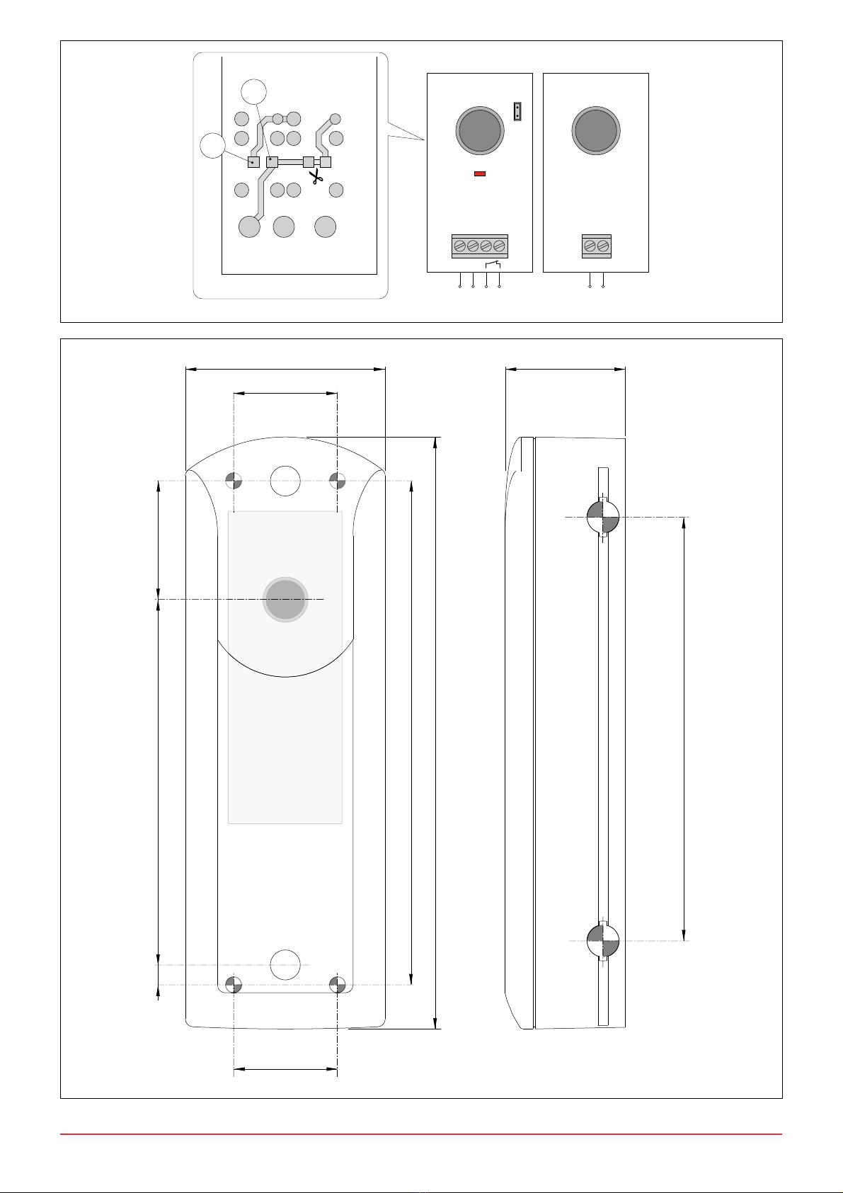
2. EINSTELLUNGEN
OFF ON
JP1 Reichweite 30 m. Reichweite 10 m.
Die Lichtschranken LAB4 werden mit einer Reichweite von 10 m geliefert.
Um die Reichweite auf 30 m zu erhöhen, JP1=OFF des Empfänger RX
einstellen (Abb. 1).
3. VERWEISE
RX Empfänger
TX Sender
LED Signalisierung des aktivierten Ausgangs
4. INSTALLATION
Die Lichtschranken LAB4 müssen unter Einhaltung der geltenden Ge-
setze und Richtlinien installiert werden.
Positionieren Sie Empfänger RX und Sender TX einerAchse zueinander.
Die Befestigung kann direkt an der Wand oder unter Verwendung der
entsprechenden Stützsäulen erfolgen (Abb. 4).
Stellen Sie die elektrischen Anschlüsse gemäß den Angaben (Abb. 1).
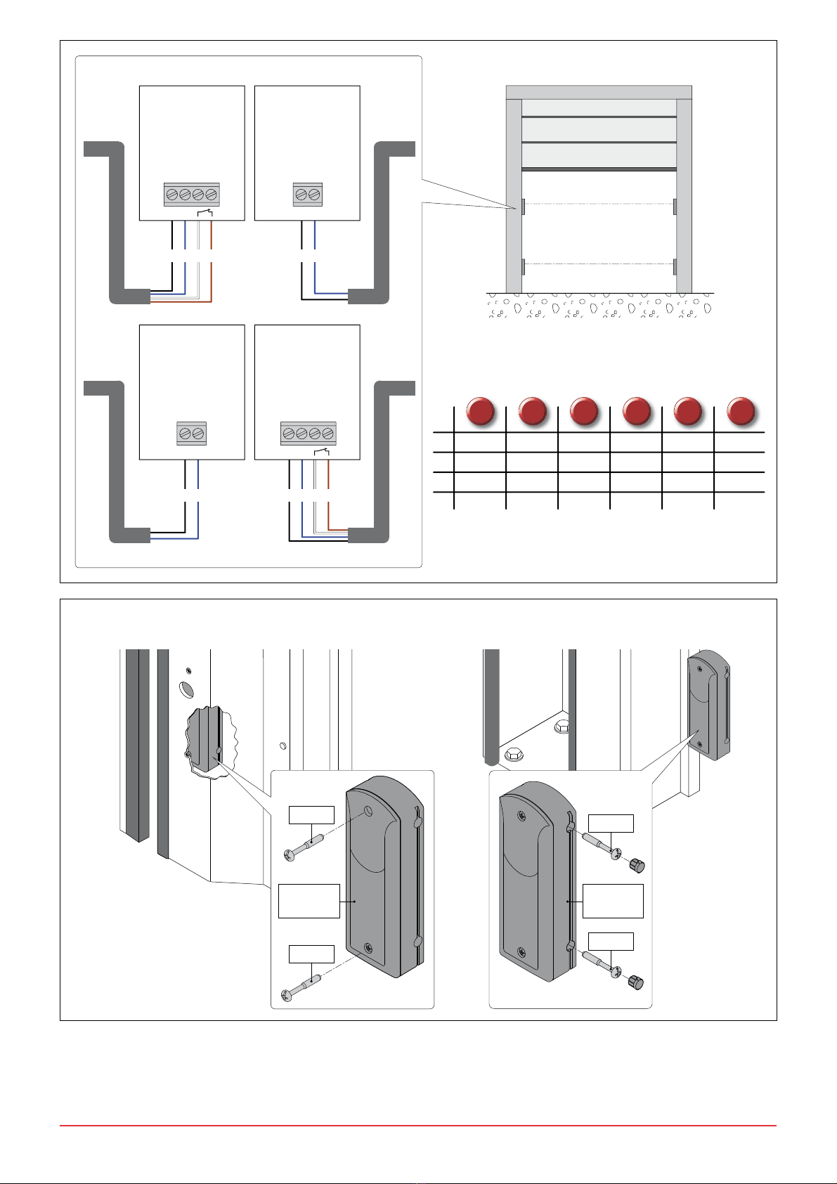
5. EINSATZ DER LICHTSCHRANKE ALS SICHERHEITSEIN-
RICHTUNG
Die Lichtschranken LAB4 werden zur Absicherung von Gefahrenberei-
chen an kraftbetätigten Toren eingesetzt.
(Abb. 1) Den N.C. an die Sicherheits- oder Stop-Kontakte der Steuerung
anschließen.
6. EINSATZ DER LICHTSCHRANKE ALS BEFEHLSEINRICHTUNG
- Durchtrennen Sie die durch gekennzeichnete Leiterbahn auf der
Lötseite von Empfänger RX.
- Brücken Sie die Punkte [C] und [D] indem Sie einen Draht auflöten.
Der Schließerkontakt (Abb. 1) wird zu einem Öffnerkontakt muss an
die Klemmen 1-3 (Öffnung) oder 1-5 (Schrittbetrieb) der Steuerung
angeschlossen werden.
7. INSTALLATION ZWEIER LICHTSCHRANKENPAARE
Um Überlagerung zwischen den zwei Lichtaschrankenpaaren zu
vermeiden, sind Empfänger RX und Sender TX über Kreuz zu installieren
der Abstand sollte Mindestens 500 mm betragen.
8. ÜBERPRÜFUNG DES BETRIEBS
Lichtschranken verschließen und außen das Etikett Dämpfungsfilter
aufkleben.
Stellen Sie durch Unterbrechung des Lichtstrahls die Umschaltung des
Relais sowie das Aufleuchten der LED auf Empfänger RX sicher.
Der Dämpfungsfilter simuliert ungünstige Umgebungsbedingungen.
Entfernen Sie den Filter nach Abschluss der Kontrollen.
9. ORDENTLICHER WARTUNGSPLAN (alle 6 Monate)
Für einen korrekten Betrieb der Lichtschranken:
- Halten Sie die Oberflächen von Empfänger RX und Sender TX stets
perfekt sauber;
- Stellen sie sicher, dass das Tor beim Unterbrechen des Licht- strahls
(Angehen der LED auf Empfänger RX) stoppt und sich wieder öffnet.
CONSIGNES GENERALES DE SECURITE
Cette notice d’installation est destinée exclusivement aux pro-
fessionels qualifiés. Lire attentivement les instructions avant de
procéder à l’installation du produit. Une installation erronée peut être
source de danger. Les materiaux de l’emballage (plastique, polystyréne,
etc ne doivent pas être abandonnés dand la nature et ne doivent pas
être laissés à la portée des enfants, car ils sont une source potentielle de
danger. Avant de procéder à l’installation, vérifier l’integrité du produit.
En cas de réparation ou de remplacement des produits, les piéces de
rechange originales doivent impérativement être utilisées. Il est indi-
spensable de conserver ces instructions et de les transmettre à d’autres
utilisateurs éventuels de ce systéme.
1. DONNEES TECHNIQUES
Alimentation 24 V =/~
Absorption 50 mA max
Portée 30 m max
Sortie N.C. 24 V =/~ / 1 A
Temperature -20° C / +55° C
Degré de protection IP55
2. REGLAGES
OFF ON
JP1 Portée 30 m. Portée 10 m.
Les cellules photoélectriques LAB4 sont fournies avec une portée ma-
xime de 10 m environ. Pour augmenter la portée jusqu’à 30 m, imposer
JP1=OFF de récepteur RX (fig. 1).
3. RÉFÉRENCES
RX Récepteur
TX Emetteur
LED Signalisation activation de sortie
4. INSTALLATION
Les photocellules LAB4 doivent être installées selon les normes et les
directives en vigueur.
Positionner récepteur RX et emetteur TX sur leur axe optique.
La fixation peut être réalisée directement sur la paroi ou en utilisant les
petites colonnes prévues à cet effet (fig. 4).
Effectuer les raccordements électriques selon les indications (fig. 1).
5. UTILISATION PHOTOCELLULE COMME DISPOSITIF DE
SÉCURITÉ
Les photocellules LAB4 servent à protéger les zones éventuelles d’écra-
sement, de cisaillement, d’entraînement et de danger en général, de la
porte ou du portail automatisés.
(Fig. 1) Relier le contact N.C. aux contacts de sécurité du tableau
electronique.
6. UTILISATION PHOTOCELLULE COMME DISPOSITIF DE
COMMANDE
- Couper la piste repérée par sur le côté soudure de récepteur RX.
- Ponter les points marqués [C] et [D].
Le contact N.C. (fig. 1) devient un contact N.O. et doit être relié aux
bornes 1-3 (ouverture) ou 1-5 (pas-à-pas) du tableau electronique.
7. INSTALLATION DE DEUX PAIRES DE PHOTOCELLULES
Pour éviter les interférences entre les deux paires de cellules photoé-
lectriques, installer récepteur RX et emetteur TX intervertis et avec les
rayons distants d’au moins 500 mm.
8. VÉRIFICATION DU FONCTIONNEMENT
Fermer la photocellule avec le volet avant et appliquer l’étiquette du filtre
d’atténuation à l’extérieur.
Interrompre le faisceau et vérifier la commutation du relais (signalisation
sonore) et l’allumage de la LED située sur récepteur RX.
Le filtre d’atténuation simule les conditions ambiantes défavorables.
Une fois les contrôles terminés, enlever le filtre.
9. PLAN D’ENTRETIEN ORDINAIRE (tous les 6 mois)
Pour le bon fonctionnement des photocellules:
- veiller à ce que les surfaces extérieures de récepteur RX et emetteur
TX soient bien propres;
- vérifier que le portail s’arrête ou rouvre si l’on interrompt le faisceau
(allumage de la LED située sur récepteur RX).
Touts droits reservés
Les informations mentionnées dans ce catalogue ont été controlées avec
la plus grande attention. Toutefois, nous déclinons toute responsabilité
en cas d’erreurs, omissions ou approximations dépendant d’exigences
techniques ou graphiques.
Alle Rechte vorbehalten
Die wiedergegebenen Daten wurden mit höchster Sorgfalt zusam-
mengestellt und überprüft. Es kann jedoch keinerlei Verantwortung für
eventuelle Fehler, Auslassungen oder Näherungen, die technischen
oder graphischen Notwendigkeiten zuzuschreiben sind, übernommen
werden.