Entrya GS-500 User manual

GSM REMOTE CONTROL
GS-500
USER MANUAL

2
2EN Manual GS-500_EN_2014-01
User Manual v1.0
SAFETY INSTRUCTIONS
Please read and follow these safety guidelines to safeguard yourself and others:
• GSM switch-gate controller GS-500 (later referred to as “the system” or “ the device”) contains a built-in radio transceiver operating in
GSM 850/900/1800/1900 MHz bands.
• DO NOT use the system where it can cause potential danger and interfere with other devices – such as medical devices.
• DO NOT use the system in hazardous environment.
• DO NOT expose the system to high humidity, chemical environment or mechanical impact.
• DO NOT attempt to repair the system yourself – any repairs must be carried out by fully qualied personnel only.
Disconnect the mains power before installing. Never install or carry out maintenance during stormy weather. The electric sock-
et that powers the system must be easily accessible.
Please use the 10-24V 50Hz ~200mA AC or 10-24V 200mA DC power supply unit that meets the EN 60950-1 standard.
Any additional device you connect to the system, such as a computer, must also be powered by an EN 60950-1 approved
supply. When connecting the power supply to the system, switching the polarity terminal places does not have any aect.
External power supply can be connected to AC mains only inside installation room
with automatic 2-pole circuit breaker capable of disconnecting circuit in the event
of short circuit or over-current condition. Open circuit breaker must have a gap
between connections of more than 3mm and the disconnection current 5A.
Phase
AC 230V
50 Hz/DC 24V
USB cable
Null
PE
GS-500
AC/DC
To switch the system o, unplug the external electric power supply from or any other linked device that the system is
powered from
A blown fuse cannot be replaced by the user. The replacement fuse has to be of the kind indicated by the manufacturer (fuse
F1 model – MINISMDC050F 0.5A).
If you use a computer for the device conguration, it must be earthed.
The WEEE (Waste Electrical and Electronic Equipment) symbol on this product (see left) means it must not be disposed of in
household waste. To prevent possible harm to human health and/or the environment, you must dispose of this product in an
approved and environmentally safe recycling facility. For further information contact your system supplier, or your local waste
authority.

3
3EN
Manual GS-500_EN_2014-01
CONTENTS
1. GENERAL INFORMATION ...........................................................................................................................................................6
2. TECHNICAL SPECIFICATIONS ....................................................................................................................................................6
2.1. Electrical & Mechanical Characteristics.........................................................................................................................................................6
2.2. Main Unit, LED Indicator & Connector Functionality ...................................................................................................................................7
2.3. Wiring Diagrams ................................................................................................................................................................................................8
3. INSTALLATION ...........................................................................................................................................................................9
4. GENERAL OPERATION .............................................................................................................................................................10
5. CONFIGURATION METHODS ....................................................................................................................................................10
5.1. SMS Text Messages.........................................................................................................................................................................................10
5.2. Programming button USR/PROG ..................................................................................................................................................................10
5.3. GS-Congurator...............................................................................................................................................................................................10
5.4. Remote Conguration via Web Browser......................................................................................................................................................10
6. SYSTEM LANGUAGE.................................................................................................................................................................12
7. SMS PASSWORD.......................................................................................................................................................................13
8. ADMINISTRATOR PHONE NUMBERS.......................................................................................................................................13
9. DATE AND TIME........................................................................................................................................................................15
9.1. Automatic Date and Time Synchronization ................................................................................................................................................15
10. USER PHONE NUMBER DATABASE ..................................................................................................................................17
10.1. User Validity and Access Restriction .......................................................................................................................................................... 20
11. OUTPUTS..........................................................................................................................................................................23
11.1. Output Names..................................................................................................................................................................................................23
11.2. Output Control by Free of Charge Phone Call ............................................................................................................................................ 24
11.3. Output Control by SMS Text Message..........................................................................................................................................................25
11.4. Output Control Conrmation by Call Back ...................................................................................................................................................27
11.5. Output Control from any Phone Number.....................................................................................................................................................27
11.6. Automatic Output Control............................................................................................................................................................................. 28
12. SCHEDULERS................................................................................................................................................................... 29
13. EVENT LOG .......................................................................................................................................................................31
14. INPUTS .............................................................................................................................................................................33
14.1. Input Names and Alarm Notications..........................................................................................................................................................33
14.2. Disabling and Enabling Inputs.......................................................................................................................................................................35
15. SYSTEM INFORMATION. INFO SMS................................................................................................................................. 36
15.1. Periodic Info SMS............................................................................................................................................................................................ 36
16. SYSTEM NOTIFICATIONS..................................................................................................................................................37
16.1. SMSC (Short Message Service Center) Phone Number.............................................................................................................................37
17. GPRS NETWORK SETTINGS .............................................................................................................................................37
18. REMOTE SYSTEM RESTART ............................................................................................................................................ 38
19. TECHNICAL SUPPORT ..................................................................................................................................................... 39
19.1. Troubleshooting ............................................................................................................................................................................................. 39
19.2. Restoring Default Parameters ..................................................................................................................................................................... 39
19.3. Updating the Firmware via USB Cable ........................................................................................................................................................ 39


5
5EN
Manual GS-500_EN_2014-01
Limited Liability
The buyer agrees that the system will reduce the risk of re, theft, burglary or other danger but that it does not guarantee against the
occurrence of such events. Entrya Technologies BVBA will not take any responsibility for the loss of personal eects, property or revenue
whilst using the system. The liability of Entrya Technologies BVBA is limited to the value of the system purchased. Entrya Technologies
BVBA is not aliated with any mobile/wireless/cellular provider and is therefore not responsible for the quality of such services.
Manufacturer Warranty
The warranty complies with statutory requirements. Your local stockist should be contacted in connection with any warranty-related
matters. Your warranty entitlements only apply to the country in which the GSM remote control was purchased. If you require after-sales
service, spare parts or accessories, please contact your specialist retailer. The warranty remains valid only if the system is used as intend-
ed, following all guidelines outlined in this manual and in accordance with the operating conditions specied. The warranty is void if the
system has been exposed to mechanical impact, chemicals, high humidity, uids, corrosive and hazardous environments or force majeure
factors.
Dear Customer,
Thank you for choosing to purchase the GSM remote control GS-500. Your thoughtful decision will ensure reliable solution for many
years as all Entrya Technologies BVBA products are manufactured to meet the highest standards.
We are condent that you will be completely satised with your product. However, in the unlikely event that you do experience a
problem, please contact the dealer from whom you made your purchase.
Entrya Technologies BVBA
Contents of Pack
Item Quantity
1. GS-500.....................................................1
2. Short manual ..........................................1
3. GSM antenna. .........................................1
Copyright © Entrya Technologies BVBA, 2013. All rights reserved
It is strictly forbidden to copy and distribute information in this document or pass to a third party without an advanced
written authorization from Entrya Technologies BVBA. Entrya Technologies BVBA reserves the right to update or modify
this document and/or related products without a warning. Hereby, Entrya Technologies BVBA declares that the GSM
switch-gate controller GS-500 is in compliance with the essential requirements and other relevant provisions of Directive
1999/5/EC. The declaration of conformity may be consulted at www.entrya.eu

6
6EN Manual GS-500_EN_2014-01
1. GENERAL INFORMATION
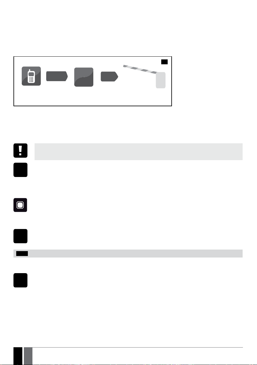
GS-500 is a micro-controller based device intended to provide access control for gate automatics, road barriers or to remotely turn ON/OFF
any electrical appliance via the GSM network.
Examples of using the system:
• Access control.
• Parking lot control of residential houses or oces.
• Gate control of private houses.
• Any electrical appliance control: lighting, watering, heating etc.
• Remote reboot of the “frozen” systems, such as computer network or a server.
Main features
• Manual output control by free of charge phone call.
• Automatic output control in accordance with the scheduled time.
• Congurable output pulse duration.
• Automatic date and time synchronization.
• Up to 5 administrators for system conguration by SMS text messages, acceptance of input alarm SMS text messages, output control
by SMS text message and free of charge phone call.
• User database capacity – up to 500 users for output control by free of charge phone call.
• User phone number validity limitation in accordance with a set deadline (date/time) or number of rings to the system.
• Output control restriction for users in accordance with the specied weekdays and time.
• Event log of 1000 events containing date and time as well as administrator/user phone number and user name who controlled the
output.
• 3 inputs with customizable alarm texts for notication on gate state or in case it gets jammed.
• Periodic self-test notication by SMS text message to administrator phone number.
2.TECHNICAL SPECIFICATIONS
2.1. Electrical & Mechanical Characteristics
Supply voltage 10-24V 50Hz ~ 200mA max / 10-24V 200mA max
Current used in standby mode up to 50mA
GSM modem frequency 850/900/1800/1900 MHz
Number of outputs 2
Output type Relay; NO (normally-open)
Maximum commuting output values 24V 50Hz ~ 0,5A / 24V 1A
Number of “low” level (negative) inputs 2
Number of “high” level (positive) inputs 1
“Low” level (negative) input value range 0... 16V -0.8... -0.4mA
“High” level (positive) input value range 5... 50V 0.17 .... 1.7mA
“Low” level (negative) and “high” level
(positive) input connection type
NO (normally-open)
Dimensions 70x90x35mm
Operating temperature range -20…+55oC (-30...+55oC with limitations)
Humidity 0-90% RH @ 0... +40 °C (non-condensing)

7
7EN
Manual GS-500_EN_2014-01
2.2. Main Unit, LED Indicator & Connector Functionality
AC/DC OUT1 OUT2 COM IN3 IN2 IN1
ANT
USB
SIM CARD
G S M
MO DE M
USR
PROG
MIC
F1
DEF
GSM (g)
GSM (r)
STATUS
Main Unit Functionality
ANT GSM antenna SMA type connector
USB Mini USB port
SIM CARD SIM card slot / holder
GSM MODEM GSM network 850/900/1800/1900 MHz modem
USR PROG button for setting user telephone numbers
GSM (g) Green light-emitting diode indicating GSM signal strength
GSM (r) Red light-emitting diode indicating SIM card status
STATUS Bue light-emitting diode indicating PROG mode
DEF Pins for restoring default settings
F1 0.5A fuse
Connector Functionality
AC/DC Power supply terminals
OUT1 Output C1 terminal
OUT2 Output C2 terminal
COM Common terminal
IN3 “Low” level (negative) input Z3 terminal; dry NO contact
IN2 “High” level (positive) input Z2 terminal; 5...50 Vdc
IN1 “Low” level (negative) input Z1 terminal; dry NO contact
1

8
8EN Manual GS-500_EN_2014-01
LED Indicator Functionality
GSM (r) SIM card status
Steady ON SIM card is not yet connected to the GSM network / SIM card is not present / PIN code enabled
OFF SIM card is operating successfully
GSM (g) GSM signal strength STATUS programmation mode
OFF No GSM signal OFF standard operation
Flashing every 1 sec. Poor Steady ON Programmation telephone
Flashing several times per sec. Medium numbers activating OUT1 &
OUT2 simultaneous
Steady ON Excellent Flashing every 1 sec. Programmation telephone
numbers activating OUT1
Flashing 2 times
per sec.
Programmation telephone
numbers activating OUT2
2.3. Wiring Diagrams
General wiring
GS-500
AC/DC
Power
supply
Gate automatics
device
RELAY1 RELAY2
+
-
COM Z3 Z2 Z1
Gate automatics
device
Example of GS-500 system wiring to gate automation device
GS-500
AC/DC OUT1 OUT2 COM IN3 IN2 IN1
Motor 1
Motor 2
power supply
accesories
230 V
230 V
Ground
Ground
Flash light
Start
Partial opening
Safety input
Relais
Motor
2
Motor
1
L N PE PE
Push
Button
24 V
Control board gate opener
Position
indicator
3
2

9
9EN
Manual GS-500_EN_2014-01
3.INSTALLATION
• The system should be installed indoors, in stationary environment ONLY.
• For the connection of input/output terminals, use 0.50 mm21 thread unshielded cable of up to 100 meters length.
1. Wire up the system in accordance with the wiring diagrams (see 2.3 Wiring Diagrams for more details).
2. Connect the GSM antenna. Based on the type of the GSM antenna supplied with GS-500 unit, follow the recommendations for the
antenna installation:
GSM
antenna
4
Never install in the following
locations:
• inside a metal cabinet
• closer than 20 cm from the
metal surface and/or power
lines
3. Disable the PIN code request and the automatic voice mail of the SIM card by inserting it into a mobile phone and following the proper
menu steps.
4. Once the PIN code and voice mail are disabled, insert the SIM card into the SIM card slot / holder of GS-500 system.
5
6
5. Make sure the antenna is connected and power up the system, wait until indicator GSM (r) goes out indicating SIM card status.
6. Once the indicator GSM (r) lights OFF, the illuminated indicator GSM (g) lights up indicating that the system has successfully connected
to the GSM network. To nd the strongest GSM signal, position the GSM antenna and follow the indications provided by GSM (g) indica-
tor (see 2.2. Main Unit, LED Indicator & Connector Functionality for more details).
7. Change the system language if necessary (see 6. SYSTEM LANGUAGE for more details).
8. Change the default SMS password (see 7. SMS PASSWORD for more details).
9. Set the phone number for Admin 1 (see 8. ADMINISTRATOR PHONE NUMBERS for more details).
10. Set system date and time (see 9. DATE AND TIME for more details).
11. Once the system is fully congured, it is ready for use. However, if you fail to receive a reply by SMS text message from the system,
please check the SMSC (Short Message Service Center) phone number. For more details regarding the SMS center phone number,
please refer to 17. SMSC (Short Message Service Center) Phone Number.
ATTENTION: The system is NOT compatible with pure 3G SIM cards. Only 2G/GSM SIM cards and 3G SIM cards with 2G/GSM prole
enabled are supported. For more details, please contact your GSM operator.
ATTENTION: We also recommend you to disable call forwarding, voice mail/text message reports on missed/busy calls and
similar services that might cause incorrect system operation. Please contact your GSM operator for more details on these services and
how to disable them.
NOTE: For maximum system reliability we recommend you do NOT use a Pay As You Go SIM card. Otherwise, in the event of insucient
credit balance on the SIM card, the system would fail to make a phone call or send SMS text messages.
NOTE: We advise you to choose the same GSM SIM provider for your system as for your mobile phone. This will ensure the fastest,
most reliable SMS text message delivery service and phone call connection.
NOTE: Even though the installation process of GS-500 is not too complicated, we still recommend to perform it by a person with basic
knowledge in electrical engineering and electronics to avoid any system damage.
10
10 EN Manual GS-500_EN_2014-01
4.GENERAL OPERATION
When a phone call is made to the phone number of the SIM card inserted in GS-500, the system will verify if the caller’s phone number exists
in the memory. If the caller is one of the 5 administrators or the phone number belongs to one of the 500 database users, the system will
reject the phone call, thus making the phone call free of charge, and open the gate. By ringing to GS-500 again, it will close the gate. If the
phone number is not recognized, the system will reject the phone call and ignore it. The GSM switch-gate controller can also control your
gate automatically in accordance with the scheduled time or by sending an SMS text message from the administrator’s phone number.
By connecting a sensor to one of the 3 inputs, the administrators can receive SMS text messages regarding the gates that failed to close
during the set time period.
User/Admin
CALL
7
5.CONFIGURATION METHODS
5.1. SMS Text Messages
!!! In this installation manual the underscore character ”_” represents one space character. Every underscore character
must be replaced by a single space character. There must be no spaces or other unnecessary characters at the beginning
and at the end of the SMS text message.
SMS
In order to congure and control the system by SMS text message, send the text command to the GS-500 system phone num-
ber from one of the preset administrator phone numbers. The structure of SMS text message consists of 4-digit SMS password
(the default SMS password is 0000 – four zeros), the parameter and value. For some parameters the value does not apply e. g.
STATUS. The variables are indicated in lower-case letters, while a valid parameter value range is indicated in brackets.
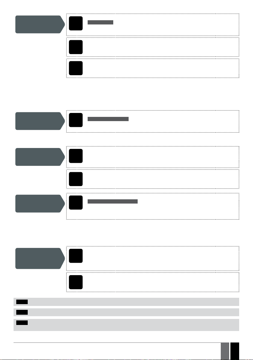
5.2. Programming button USR/PROG
With the button USR / PROG it is possible to add or delete phone numbers in a simple way. This option can not be used until
the SMS password and at least one administrator is congured with SMS text messages or using the GS-Congurator soft-
ware via USB or GPRS.
GS-Congurator is freeware and can be downloaded at: www.entrya.eu/en/download
5.3. GS-Congurator
Cong
Tool
Software GS-Congurator is intended for GS-500 GSM remote control conguration via USB port locally. This software simpli-
es system conguration process by allowing to use a personal computer in the process. Before starting to use GS-Congu-
rator software, please read the user guide provided in the software’s HELP section.
GS-Congurator is freeware and can be downloaded at: www.entrya.eu/en/download
NOTE: GS-Congurator is secured with SMS password. The default SMS password is 0000 (see 7. SMS PASSWORD).
5.4. Remote Conguration via Web Browser
WEB
BROWSER
The system comes equipped with a remote conguration feature allowing to congure the parameters via any available web
browser. Before remotely connecting to GS-500 via GPRS connection, ensure that:
• SIM card is inserted into the SIM CARD slot (see 2.2. Main Unit, LED & Connector Functionality).
• Mobile internet service (GPRS) is enabled on the SIM card.
• GS-500 is powered up.
• Default SMS password is changed to a new 4-digit password (see 7. SMS PASSWORD).
• Admin 1 phone number is set up (see 8. ADMINISTRATOR PHONE NUMBERS).
• APN, user name and password are set up (see 17. GPRS NETWORK SETTINGS).
GS-500
11
11EN
Manual GS-500_EN_2014-01
View remote
conguration
parameters
SMS
SMS text message content:
ssss_SETGPRS?
Value: ssss – 4-digit SMS password.
Example: 1111_SETGPRS?
Cong
Tool This operation may be carried out from the PC using the GS-Congurator software.
WEB
BROWSER This operation may be remotely carried out from the PC using the web browser.
5.4.1. Establishing Remote Connection
1. In order to activate a remote connection, please send the following SMS text message from user phone number.
Upon the successful SMS text message delivery, the system establishes a connection session for 20 minutes.
An SMS reply, containing temporal user name and password, will be sent shortly after.
Establish remote
connection SMS
SMS text message content:
ssss_CONNECT:PROFILE1
Value: ssss – 4-digit new SMS password.
Example: 1111_CONNECT:PROFILE1
To set a dierent session duration or connect for a custom session duration, please refer to the following conguration methods.
Set session duration Cong
Tool This operation may be carried out from the PC using the GS-Congurator software.
WEB
BROWSER This operation may be remotely carried out from the PC using the web browser.
Establish remote
connection for custom
session duration
SMS
SMS text message content:
ssss_CONNECT:TIMEOUT:ses-d
Value: ssss – 4-digit new SMS password; ses-d – session duration, range – [0... 14400] mi-
nutes.
Example: 1111_CONNECT:TIMEOUT:120
Alternatively, the system supports remote connection establishment by making a phone call from the administrator phone number to
the system. Once the call is received, the system rejects the call thus making it free of charge and replies with the login details by SMS
text message to the administrator phone number. By default, this feature is disabled. To enable/disable it, please refer to the following
conguration methods.
Enable/disable
remote connection
establishment by
phone call
Cong
Tool This operation may be carried out from the PC using the GS-Congurator software.
WEB
BROWSER This operation may be remotely carried out from the PC using the web browser.
NOTE: 0 value sets unlimited session duration.
NOTE: GS-Congurator software and remote conguration web interface allows to set the unlimited session duration value.
NOTE: Once the remote connection establishment by phone call is enabled, the specied administrator will no longer be able to
control the output via free of charge phone call.

12
12 EN Manual GS-500_EN_2014-01
2. Open a web browser and type in http://gs-congurator.entrya.eu/
3. Enter the received login details and press Login button.
4. After the system conguration is complete, use one of the following methods to end the conguration process:
• Wait for the session timeout and the system to reply with an SMS text message conrming the end of the session.
• Shut down the connection with the conguration server at any time by sending an SMS text message.
Shut down the
connection with
conguration server
SMS
SMS text message content:
ssss_STOP
Value: ssss – 4-digit new SMS password.
Example: 1111_STOP
ATTENTION: Output control is disabled during the remote conguration process.
6.SYSTEM LANGUAGE
The system comes equipped with a multiple languages for communication with the administrator by SMS text messages. The default
system language depends on the rmware, which is based on the customer’s location.
List of currently available system languages:
• English
• French
• Dutch
• German
• Italian
• Spanish
Set system language SMS
SMS text message content:
LN
Value: LN – language index; range – [EN – English, FR – French, NL – Dutch, DE - German,
IT – Italian, SP – Spanish].
Example: FR
Cong
Tool This operation may be carried out from the PC using the GS-Congurator software.
WEB
BROWSER This operation may be remotely carried out from the PC using the web browser.
NOTE: To change the language by SMS text message once the system has already been congured, you need to reset the device to
the default conguration. For more details on how to do this, please refer to 19.2. Restoring Default Parameters.
13
13EN
Manual GS-500_EN_2014-01
7.SMS PASSWORD
For security reasons, the system uses the following type of password:
• SMS password – 4-digit password used for system conguration and control from administrator phone number by SMS text
messages and logging in to GS-Congurator’s software . By default, the SMS password is 0000, which MUST be changed!
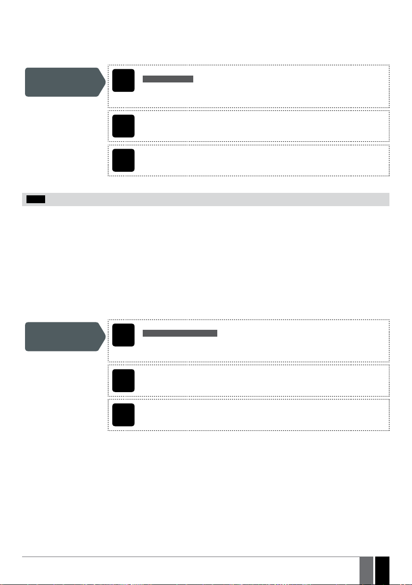
Set SMS password SMS
SMS text message content:
wwww_PSW_ssss
Value: wwww – 4-digit default SMS password; ssss – 4-digit new SMS password; range –
[0001... 9999].
Example: 0000_PSW_1111
Cong
Tool This operation may be carried out from the PC using the GS-Congurator software.
WEB
BROWSER This operation may be remotely carried out from the PC using the web browser.
NOTE: The system rejects the SMS text messages containing wrong SMS password even from a preset administrator phone number.
8.ADMINISTRATOR PHONE NUMBERS
The system supports up to 5 administrator phone numbers identied as Admin 1 through 5. When the administrator phone number
is set, the administrator will be able to congure and control the system by SMS text messages as well as by free of charge phone
call and receive the alarm SMS text messages from the system’s inputs (see 14.1. Input Names and Alarm Notication).
GS-500 allows to assign output C1, output C2 or both outputs (simultaneous control) to a certain administrator.
By default, the system ignores any incoming calls and SMS text messages from a non-preset phone number as well as it rejects the SMS
text messages containing wrong SMS password even from a preset administrator phone number. For more details on how to enable output
control from a non-preset phone number, please refer to 11.5. Output Control from any Phone Number.
To set Admin 1 phone number is mandatory, while the other 4 are optional. The supported phone number format is the following:
• International (without (+) plus) – The phone numbers must be entered starting with an international country code in the following
format: [international code][area code][local number], example for UK: 4417091111111.
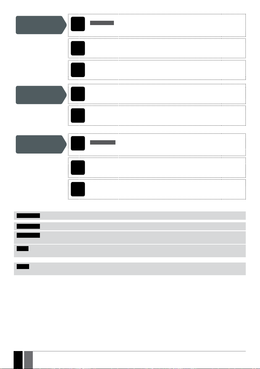
Set administrator
phone number SMS
SMS text message content:
ssss_NRas:ttteeellnnuumm
Value: ssss – 4-digit SMS password; as – administrator phone number slot, range – [1... 5];
ttteeellnnuumm – up to 15 digits administrator phone number.
Example: 1111_NR1:4417091111111
Cong
Tool This operation may be carried out from the PC using the GS-Congurator software.
WEB
BROWSER This operation may be remotely carried out from the PC using the web browser.
14
14 EN Manual GS-500_EN_2014-01
View administrator
phone numbers SMS
SMS text message content:
ssss_HELPNR
Value: ssss – 4-digit SMS password.
Example: 1111_HELPNR
Cong
Tool This operation may be carried out from the PC using the GS-Congurator software.
WEB
BROWSER This operation may be remotely carried out from the PC using the web browser.
Assign output
(-s) to individual
administrator
Cong
Tool This operation may be carried out from the PC using the GS-Congurator software.
WEB
BROWSER This operation may be remotely carried out from the PC using the web browser.
Delete administrator
phone number SMS
SMS text message content:
ssss_NRas:DEL
Value: ssss – 4-digit SMS password; as – administrator phone number slot, range – [2... 5].
Example: 1111_NR2:DEL
Cong
Tool This operation may be carried out from the PC using the GS-Congurator software.
WEB
BROWSER This operation may be remotely carried out from the PC using the web browser.
ATTENTION: NEVER set a phone number of the device’s SIM card as an administrator phone number!
ATTENTION: Once Admin 1 phone number is set, the system will restrict only to modify it
ATTENTION: Multiple administrator phone numbers can be set by a single SMS text message, Example: 1111_NR1:4417091111111_
NR5:4417091111112_NR2:4417091111113_NR3: 4417091111114
NOTE: Multiple administrator phone numbers can be deleted by a single SMS text message, Example: 1111_NR2:DEL_NR4:DEL_
NR3:DEL
NOTE : The administrator can control any output by SMS text message regardless of the output assigned to the administrator phone
number (see 11.3. Output Control by SMS Text Message).
For more details on output control, please refer to 11. OUTPUTS.

15
15EN
Manual GS-500_EN_2014-01
9.DATE AND TIME
The system comes equipped with internal real-time clock (RTC) that keeps track of the current date and time. Once the system is up and
running, the user must set the correct date and time, otherwise the system will not operate properly. After shutting down and starting up
the system, the date and time must be set again.
By default, in order to avoid manual date and time set up, the automatic date and time synchronization feature is enabled
(see 9.1. Automatic Date and Time Synchronization). However, some SIM-card providers may not support this service.
Set date and time SMS
SMS text message content:
ssss_yyyy.mm.dd_hr:mn
Value: ssss – 4-digit SMS password; yyyy – year; mm – month, range – [01... 12]; dd – day,
range – [01... 31]; hr – hours, range – [00... 23]; mn – minutes, range – [00... 59].
Example: 1111_2013.03.16_14:33
Cong
Tool This operation may be carried out from the PC using the GS-Congurator software.
WEB
BROWSER This operation may be remotely carried out from the PC using the web browser.
9.1. Automatic Date and Time Synchronization
This feature enables the system to set the date and time automatically without the user being involved in this process. The system supports
the following methods of automatic date and time synchronization that are used automatically on system start-up and periodically (by
default – every 30 days):
• Via GSM network – Once enabled, the system automatically sends a date/time request to the GSM operator. This method is the
most accurate synchronization method. Some GSM operators might not support it.
• By SMS text message – Once enabled, the system automatically sends the SMS text message to its own phone number and
retrieves the date and time from the SMS text message reply, as the included date and time is set by the SMSC (SMS center). This
method is not as accurate as the synchronization via GSM network, but always eective.
By default, synchronization via GSM network is enabled. To disable/enable automatic date and time synchronization via GSM network,
please refer to the following conguration methods.
Enable/disable
synchronization via
GSM network
Cong
Tool This operation may be carried out from the PC using the GS-Congurator software.
WEB
BROWSER This operation may be remotely carried out from the PC using the web browser.
By default, synchronization by SMS text message is disabled. To enable/disable automatic date and time synchronization by SMS text
message, please enter/remove device phone number using one of the following conguration methods.
Enter/remove device
phone number for
synchronization by
SMS text message
Cong
Tool This operation may be carried out from the PC using the GS-Congurator software.
WEB
BROWSER This operation may be remotely carried out from the PC using the web browser.

16
16 EN Manual GS-500_EN_2014-01
By default, the date and time synchronization period is 30 days. To set a dierent period, please refer to the following conguration
methods.
Set synchronization
period
Cong
Tool This operation may be carried out from the PC using the GS-Congurator software.
WEB
BROWSER This operation may be remotely carried out from the PC using the web browser.
NOTE: When setting up automatic date and time synchronization feature remotely, you may wish to restart the system when done.
For more details, please refer to 18. REMOTE SYSTEM RESTART.
NOTE: The 0 value disables periodic date and time synchronization.
NOTE: When both synchronization methods are enabled, the system will always attempt to synchronize date and time via GSM net-
work every time the system shuts down and starts up again and in accordance with the set period value. In the event of rst method’s
failure, the system will attempt to use the SMS text message method as a backup.

17
17EN
Manual GS-500_EN_2014-01
10. USER PHONE NUMBER DATABASE
The system comes equipped with a user database of 500 user capacity. When the phone number is set, the user will be able to control the
output (-s) by free of charge phone call. GS-500 user database allows to assign output C1, output C2 or both outputs (simultaneous control)
to a certain user. The supported phone number format is the following:
• International (without (+) plus) – The phone numbers must be entered starting with an international country code in the
following format: [international code][area code][local number], example for UK: 4417091111111.
GS-500 user database supports user validity and access restriction features. For more details, please refer to 10.1. User Validity and
Access Restriction.
Optionally, a user name can be set that typically species the owner’s name of a certain phone number, for example: John.
The phone number and user name (if any) are used when searching for a certain user in the database as well as they are automatically
added in the event log after the successful output control event (see 13. EVENT LOG).
Add user phone
number (and user
name)
SMS
SMS text message content:
ssss_N:ttteeellnnuumm or ssss_N:ttteeellnnuumm:user-name
Value: ssss – 4-digit SMS password; ttteeellnnuumm – up to 15 digits user phone number;
user-name – up to 16 characters user name.
Example: 1111_N:4417091111111:John
To add the user phone number using the USR/PROG button, please refer to the
following steps:
Add user phone number and assign output OUT1 to it
1. Keep the USR/PROG button pressed for 5 seconds.
2. The blue STATUS-LED light starts ashing every 2 sec for 10 minutes or until the USR/
PROG button is pressed again briey.
3. Dial the system‘s phone number before the 10-minute period expires using the mobile
phone to program.
4. The blue LED goes out (OFF).
5. Phone number is added to user database and output OUT1 is assigned to it.
Add user phone number and assign output OUT2 to it
1. Keep the USR/PROG button pressed for 10 seconds.
2. The blue STATUS LED light starts ashing every 1 sec for 10 minutes or until the USR/
PROG button is pressed again briey.
3. Dial the system‘s phone number before the 10-minute period expires using the mobile
phone to program.
4. The blue STATUS LED goes out (OFF).
5. Phone number is added to user database and output OUT2 is assigned to it.
Add user phone number and assign both outputs (OUT1 and OUT2) to it
1. Press the USR/PROG button shortly.
2. The blue STATUS LED light will light up for 10 minutes or until the USR/PROG button is
pressed again briey.
3. Dial the system‘s phone number before the 10-minute period expires using the mobile
phone to program.
4. The blue STATUS LED light goes out (OFF).
5. Phone number is added to user database and both outputs are assigned to it.
Cong
Tool This operation may be carried out from the PC using the GS-Congurator software.
WEB
BROWSER This operation may be remotely carried out from the PC using the web browser.
ATTENTION: Space and colon characters are NOT allowed in the user names.
NOTE: Multiple users can be added by a single SMS text message, Example: 1111_N:4417091111111:John_ 4417091111112:_
4417091111113:Tom
NOTE: Multiple users can be deleted by a single SMS text message, Example: 1111_D:John_ 4417091111113_Mark
For more details on output control, please refer to 11. OUTPUTS.
18
18 EN Manual GS-500_EN_2014-01
View users phone
numbers SMS
SMS text message content:
ssss_GETALLNUMBERS
Value: ssss – 4-digit SMS password.
Example: 1111_GETALLNUMBERS
Cong
Tool This operation may be carried out from the PC using the GS-Congurator software.
WEB
BROWSER This operation may be remotely carried out from the PC using the web browser.
Search for user by
phone number or
name
SMS
SMS text message content:
ssss_T:ttteeellnnuumm or ssss_T:user-name
Value: ssss – 4-digit SMS password; ttteeellnnuumm – up to 15 digits user phone number;
user-name – up to 16 characters user name.
Example: 1111_T:John
Cong
Tool This operation may be carried out from the PC using the GS-Congurator software.
WEB
BROWSER This operation may be remotely carried out from the PC using the web browser.
Assign output (-s) to
individual user SMS
SMS text message content:
ssss_OUTPUT_ttteeellnnuumm_o or ssss_OUTPUT_user-name_o
Value: ssss – 4-digit SMS password; ttteeellnnuumm – up to 15 digits user phone number;
o– output number; range [1 – output C1; 2 – output C2; 3 – both outputs]; user-name – up
to 16 characters user name.
Example: 1111_OUTPUT_4417091111111_2
Cong
Tool This operation may be carried out from the PC using the GS-Congurator software.
WEB
BROWSER This operation may be remotely carried out from the PC using the web browser.
Delete individual user SMS
SMS text message content:
ssss_D:ttteeellnnuumm or ssss_D:user-name
Value: ssss – 4-digit SMS password; ttteeellnnuumm – up to 15 digits user phone number;
user-name – up to 16 characters user name.
Example: 1111_GETALLNUMBERS
1. Press the USR/PROG button once.
2. The blue STATUS LED light will light up for 10 minutes or until the USR/PROG bu-
tton is pressed again briey.
3. Dial the system‘s phone number before the 10-minute period expires using the
users phone to delete.
4. User deleted from the database.
Cong
Tool This operation may be carried out from the PC using the GS-Congurator software.
WEB
BROWSER This operation may be remotely carried out from the PC using the web browser.

19
19EN
Manual GS-500_EN_2014-01
Delete all users SMS
SMS text message content:
ssss_D:ALL
Value: ssss – 4-digit SMS password.
Example: 1111_D:ALL
1. Keep the USR/PROG button pressed for 30 seconds.
2. The blue STATUS LED light will start to ash rapidly and then stops.
3. All user numbers are deleted.
Cong
Tool This operation may be carried out from the PC using the GS-Congurator software.
WEB
BROWSER This operation may be remotely carried out from the PC using the web browser.
The user database can be exported/imported to/from a .csv le for backup purposes or for a convenient user database management. To
export/import an existing user database, please refer to the following conguration method.
Export/import
existing user database
from/to le
Cong
Tool This operation may be carried out from the PC using the GS-Congurator software.
By default, the user database is enabled and output control by all database users is permitted. To deny output control instead of deleting
all users from the database, please disable the user database using one of the following conguration methods.
Disable user database SMS
SMS text message content:
ssss_DBM_OFF
Value: ssss – 4-digit SMS password.
Example: 1111_DBM_OFF
Cong
Tool This operation may be carried out from the PC using the GS-Congurator software.
WEB
BROWSER This operation may be remotely carried out from the PC using the web browser.
To enable user database, please refer to the following conguration methods.
Enable user database SMS
SMS text message content:
ssss_DBM_ON
Value: ssss – 4-digit SMS password.
Example: 1111_DBM_ON
Cong
Tool This operation may be carried out from the PC using the GS-Congurator software.
WEB
BROWSER This operation may be remotely carried out from the PC using the web browser.
ATTENTION: Space and colon characters are NOT allowed in the user names.
NOTE: Multiple users can be added by a single SMS text message, Example: 1111_N:4417091111111:John_ 4417091111112:_
4417091111113:Tom
NOTE: Multiple users can be deleted by a single SMS text message, Example: 1111_D:John_ 4417091111113_Mark
For more details on output control, please refer to 11. OUTPUTS.

20
20 EN Manual GS-500_EN_2014-01
10.1. User Validity and Access Restriction
The system allows to restrict access in accordance with the scheduler assigned to a certain user. When one or more schedulers are
assigned, the user will be able to control the output only on the specied weekdays and time set up in the scheduler. The system allows to
assign up to 8 dierent schedulers. For more details on how to set up the schedulers, please refer to 12. SCHEDULERS.
In addition, the system allows to limit the user validity by the following methods:
• Deadline (valid until) – When a specied date and time hits, the user will be automatically deleted from the database.
• Limited number of calls (Ring counter) – When a specied number of phone calls to the system expires, the user will be
automatically deleted from the database.
Assign scheduler to
individual user SMS
SMS text message content:
ssss_NSCHED_ttteeellnnuumm_c:ON or ssss_NSCHED_user-name_c:ON
Value: ssss – 4-digit SMS password; ttteeellnnuumm – up to 15 digits user phone number;
c– scheduler number; range – [1... 8]; user-name – up to 16 characters user name.
Example: 1111_NSCHED_John_5:ON
Cong
Tool This operation may be carried out from the PC using the GS-Congurator software.
WEB
BROWSER This operation may be remotely carried out from the PC using the web browser.
Remove scheduler
from individual user SMS
SMS text message content:
ssss_NSCHED_ttteeellnnuumm_c:OFF or ssss_NSCHED_user-name_c:OFF
Value: ssss – 4-digit SMS password; ttteeellnnuumm – up to 15 digits user phone number;
c– scheduler number; range – [1... 8]; user-name – up to 16 characters user name.
Example: 1111_NSCHED_John_5:OFF
Cong
Tool This operation may be carried out from the PC using the GS-Congurator software.
WEB
BROWSER This operation may be remotely carried out from the PC using the web browser.
Set deadline for
individual user SMS
SMS text message content:
ssss_EXPIRYTIME_ttteeellnnuumm_yyyy.mm.dd_hr:mn or ssss_EXPIRYTIME_user-
name_yyyy.mm.dd_hr:mn
Value: ssss – 4-digit SMS password; ttteeellnnuumm – up to 15 digits user phone number;
yyyy – year; mm – month, range – [01... 12]; dd – day, range – [01... 31]; hr – hours, range
– [00... 23]; mn – minutes, range – [00... 59]; user-name – up to 16 characters user name.
Example: 1111_EXPIRYTIME_John_2015.06.29_19:35
Cong
Tool This operation may be carried out from the PC using the GS-Congurator software.
WEB
BROWSER This operation may be remotely carried out from the PC using the web browser.
Table of contents
Other Entrya Gate Opener manuals


