manuals.online logo
Brands
  1. Home
  2. •
  3. Brands
  4. •
  5. Casit
  6. •
  7. Gate Opener
  8. •
  9. Casit SCORRY500J User manual

Casit SCORRY500J User manual

1 Rev02 del 8 settembre 2022
Stab.: Strada Pietra Alta 1 –C.a.p. 10040 CASELETTE (TO) Italy Tel. 011/9688230 - 9688170 Fax
011/9688363 –Partita IVA 0050659.001.7 - Reg. Trib. Torino N.654/62 - C.C.I.A.A. 333122 - M: T0024777
Sito www.casit.it E-Mail info@casit.it
SCORRY500J-
SCORRY510J/C1
SCORRY800J
SCORRY1000J
Operatori Cancelli scorrevoli kg. 500 - 800 - 1000
Sliding Gate Operators kg. 500 - 800 - 1000
Operateur portail coulissant kg. 500 - 800 –1000
AVVERTENZE GENERALI PER LA
SICUREZZA
USO –Avvertenze per l’utente
Le presenti avvertenze sono parte integrante ed
essenziale del prodotto e devono essere consegnate
all’utilizzatore.
Leggerle attentamente in quanto forniscono importanti
indicazioni riguardanti la sicurezza di installazione, uso
e manutenzione. È necessario conservare queste
istruzioni e trasmetterle ad eventuali subentranti
nell’uso dell’impianto.
Questo prodotto dovrà essere destinato solo all’uso
per il quale è stato espressamente concepito.
Ogni altro uso è da considerarsi improprio e quindi
pericoloso.
Il costruttore non può essere considerato responsabile
per eventuali danni causati da usi impropri, erronei ed
irragionevoli.
2 Rev02 del 8 ottobre 2022
Evitare di operare in prossimità delle cerniere o organi
meccanici in movimento. Non entrare nel raggio di
azione della porta o cancello motorizzati mentre è in
movimento.
Non opporsi al moto della porta o cancello motorizzati
poiché può causare situazioni di pericolo. Non
permettere ai bambini di giocare o sostare nel raggio
di azione della porta o cancello motorizzati. Tenere
fuori dalla portata dei bambini i radiocomandi e/o
qualsiasi altro dispositivo di comando, per evitare che
la porta o cancello motorizzati possa essere azionata
involontariamente. In caso di guasto o di cattivo
funzionamento del prodotto, disinserire l’interruttore di
alimentazione, astenendosi da qualsiasi tentativo di
riparazione o di intervento diretto e rivolgersi solo a
personale professionalmente competente. Il mancato
rispetto di quanto sopra può creare situazioni di
pericolo.
L’utente può solo eseguire la manovra manuale.
Qualsiasi intervento di pulizia, manutenzione o
riparazione, deve essere effettuato da personale
professionalmente competente.
Per garantire l’efficienza dell’impianto ed il suo corretto
funzionamento è indispensabile attenersi alle
indicazioni del costruttore facendo effettuare da
personale professionalmente competente la
manutenzione periodica della porta o cancello
motorizzati.
In particolare si raccomanda la verifica periodica del
corretto funzionamento di tutti i dispositivi di sicurezza.
Gli interventi di installazione, manutenzione e
riparazione devono essere documentati e tenuti a
disposizione dell’utilizzatore.
INSTALLAZIONE –Istruzioni per l’installatore
L’installazione deve essere eseguita da personale
professionalmente competente. L’installazione, i
collegamenti elettrici e le regolazioni devono essere
effettuati nell’osservanza della Buona Tecnica e in
ottemperanza alle norme vigenti. Leggere
attentamente le istruzioni prima di iniziare
l’installazione del prodotto. Una errata installazione
può essere fonte di pericolo.
I materiali dell’imballaggio (plastica, polistirolo, ecc.)
non vanno dispersi nell’ambiente e non devono essere
lasciati alla portata dei bambini in quanto potenziali
fonti di pericolo.
Prima di iniziare l’installazione verificare l’integrità del
prodotto.
Non installare il prodotto in ambiente e atmosfera
esplosivi: presenza di gas o fumi infiammabili
costituiscono un grave pericolo per la sicurezza.
Prima di installare la motorizzazione, apportare tutte le
modifiche strutturali relative alla realizzazione dei
franchi di sicurezza ed alla protezione o segregazione
di tutte le zone di schiacciamento, cesoiamento,
convogliamento e di pericolo in genere. Verificare che
la struttura esistente abbia i necessari requisiti di
robustezza e stabilità.
Il costruttore della motorizzazione non è responsabile
dell’inosservanza della Buona Tecnica nella
costruzione degli infissi da motorizzare, nonché delle
deformazioni che dovessero intervenire nell’utilizzo.
I dispositivi di sicurezza (fotocellule, coste sensibili,
stop di emergenza,ecc.) devono essere installati
tenendo in considerazione: le normative e le direttive
in vigore, i criteri della Buona Tecnica, l’ambiente di
installazione, la logica di funzionamento del sistema e
le forze sviluppate dalla porta o cancello motorizzati. I
dispositivi di sicurezza devono proteggere eventuali
zone di schiacciamento, cesoiamento, convogliamento
e di pericolo in genere, della porta o cancello
motorizzati.
Applicare le segnalazioni previste dalle norme vigenti
per individuare le zone pericolose. Ogni installazione
deve riportare in modo visibile l’indicazione dei dati
identificativi della porta o cancello motorizzati.
Prima di collegare l’alimentazione elettrica accertarsi
che i dati di targa siano rispondenti a quelli della rete
di distribuzione elettrica.
Prevedere sulla rete di alimentazione un
interruttore/sezionatore onnipolare con distanza
d’apertura dei contatti uguale o superiore a 3 mm.
Verificare che a monte dell’impianto elettrico vi siano
un interruttore differenziale e una protezione di
sovracorrente adeguati.
Collegare la porta o cancello motorizzati a un’efficace
impianto di messa a terra eseguito come previsto dalle
vigenti norme di sicurezza.
Il costruttore della motorizzazione declina ogni
responsabilità qualora vengano installati componenti
incompatibili ai fini della sicurezza e del buon
funzionamento. Per l’eventuale riparazione o sostituzione
dei prodotti dovranno essere utilizzati esclusivamente
ricambi originali.
L’installatore deve fornire tutte le informazioni relative
al funzionamento automatico, manuale e di emergenza
della porta o cancello motorizzati, è consegnare
all’utilizzatore dell’impianto le istruzioni d’uso.
GENERAL SAFETY PRECAUTIONS
USE –Warnings for the User
The following precautions are an integral and
essential part of the products and must be supplied
to the user.
Read them carefully as they contain important
indications for the safe installation, use and
maintenance.
These instructions must be kept and forwarded to all
possible future user of the system.
This product must be used only for that which it has
been expressely designed. Any other use is to be
considered improper and therefore dangerous.
The manufacturer cannot be held responsible for
possible damage caused by improper, erroneous or
unreasonable use. Avoid operating in the proximity
of the hinges or moving mechanical parts.
Do not enter the field of action of the motorised door
or gate while in motion.
Do not obstruct the motion of the motorised door or
gate as this may cause a situation of danger.
Do not allow children to play or stay within the field of
action of the motorised door or gate. Keep remote
control or any other control devices out of the reach
of children, in order to avoid possible involuntary
activation of the motorised door or gate.
In case of breakdown or malfunctioning of the
product, disconnect from the mains, do not attempt
to repair or intervene directly and contact only
qualified personnel.
Failure to comply with the above may create a
situation of danger.
The user can only execute the manual drive.
All cleaning, maintenance or repair work must be
carried out by qualified personnel.
In order to guarantee that the system works
efficiently and correctly it is indispensable to comply
with the manufacturer’s indications thus having the
periodic maintenance of the motorised door or gate
carried out by qualified personnel.
In particular regular checks are recommended in
order to verify that the safety devices are operating
correctly.
All installation, maintenance and repair work must be
documented and made available to the user.
INSTALLATION –Instructions for the fitter
The installation must be carried out by qualified
personnel. The installation, the electrical connections
and the settings must be completed in conformity
with good workmanship and with the laws in force.
Read the instructions carefully before beginning to
instal the product. Incorrect installation may be
source of danger.
Packaging materials (plastic, polystyrene, etc.) must
not be allowed to litter the environment and must be
kept out of the reach of children for whom they may
be a source of danger.
Before beginning the installation check that the
product is in perfect condition. Do not install the
product in explosive areas and atmospheres: the
presence of flammable gas or fumes represents a
serious threat to safety.
Before installing the motorisation device, make all
the structural modifications necessary in order to
create safety clearance and to guard or isolate all the
compression, shearing, trapping and general danger
areas. Check that the existing structure has the
necessary strength and stability.
The manufacturer of the motorisation device is not
responsible for the non-observance of workmanship
in the construction of the frames to be motorised, nor
for deformations that may occur during use.
The safety devices (photoelectric cells, mechanical
obstruction sensor, emergency stop, etc.) must be
installed taking into account: the provisions and the
directives in force, good workmanship criteria, the
installation area, the functional logic of the system
and the forces developed by the motorised door or
gate.
The safety devices must protect against
compression, shearing, trapping and general danger
areas of the motorized door or gate.
Display the signs required by law to identify danger
areas. Each installation must bear a visible indication
of the data identifying the motorised door or gate.
Before connecting to the mains check that the rating
is correct for the destination power requirements. A
multipolar isolation switch minimum contact gaps of
3mm must be included in the mains supply.
Check that upstream of the electrical installation
there is an adequate differential switch and a suitable
circuit breaker. Ensure that the motorised door or
gate has an earth terminal in accordance with the
safety regulations in force. The manufacturer of the
motorising device declines all responsibility in cases
where components which are incompatible with the
safe and correct operation of the product have been
installed. For repairs or replacement of products only
original spare must be used.
The fitter must supply all information concerning
the automatic, the manual and the emergency
operation of the motorised door or gate, and
must provide the user of the device with the
operating instructions.
CONSIGNES GENERALES DE SECURITE
UTILISATION –Conseignes pour l’utilisateur
Ces consignes sont partie intégrante et essentielle
du produit et doivent être remises à l’utilisateur. Lire
ces consignes attentivement, car elles contiennent
des instructions concernant la sécurité de
l’installation, de l’utilisation et de l’entretien de ce
système.
Il est indispensable de conserver ces instructions et
de les transmettre à d’autres utilisateurs éventuels
de ce système.
Ce produit doit être destiné exclusivement à
l’utilisation pour laquelle il a été conçu. Toute autre
utilisation est inappropriée et par conséquent
dangereuse.
Le constructeur ne peut être tenu pour responsable
en cas d’éventuels dommages causés par une
utilisation inappropriée, erronée et irrationnelle.
Eviter de manoeuvrer à proximité des charnières ou
des organes mécaniques en mouvement. Ne pas
entrer dans le rayon d’action de la porte ou du portail
automatisés lorqu’ils sont en mouvement. Ne pas
s’opposer au mouvement de la porte ou du portail
automatisés car cela peut être source de danger.
Ne pas laisser des enfants jouer ou se tenir dans le
rayon d’action de la porte ou du portail automatisés.
Garder hors de la portée des enfants les
radiocommandes et/ou tout autre dispositif de
commande, afin d’éviter que la porte ou le portail
automatisés puissent être actionnés
involontairement.
En cas de panne ou de mauvais fonctionnement du
produit, débrancher l’interrupteur de secteur et
s’abstenir de toute tentative de réparation ou
d’intervention directe. S’adresser uniquement à un
professionnel compétent.
Le non-respect de ces instructions peut être cause
de danger.
L'utilisateur peut seulement exécuter la
dépannage manuel.
Afin de garantir l’efficacité du système et son
fonctionnement correct, il est indispensable
d’observer les instructions du constructeur en
s’adressant à un professionnel compétent pour
l’entretien périodique de la porte ou du portail
automatisés. Plus particulièrement, il est
recommandé de procéder à une vérification
périodique du fonctionnement correct de tous les
dispositifs de sécurité.
Les interventions d’installation, d’entretien et de
réparation doivent être documentées et mises à la
disposition de l’utilisateur.
INSTALLATION –instructions pour l’installateur
L’installation doit être effectuée par un professionnel
compétent. L’installation, le raccordement
électrique et les réglages doivent être effectués
selon règles de Bonne Technique et respecter la
réglementation en vigueur.
Lire attentivement les instructions avant de procéder
à l’installation du produit. Une installation erronée
peut être source de danger. Les materiaux de
l’emballage (plastique, polystyrène, etc.) ne doivent
pas être abandonnés dans la nature et ne doivent
pas être laissés à la portée des enfants, car ils sont
une source potentielle de danger.
Avant de procéder à l’installation, vérifier l’intégrité
du produit.
Ne pas installer le produit à proximité de matières
explosives : la présence de gaz ou de vapeurs
inflammables représente un grave danger pour la
sécurité. Avant d’installer les automatismes, apporter
toutes les modifications structurelles relatives à la
realisation des distances de sécurité et à la
protection ou ségrégation de toutes les zones
d’écrasement, de cisaillement, d’entraînement et de
danger en général.
Vérifier que la structure existante ait les qualités requises
de robustesse et de stabilité. Le constructeur des
automatismes n’est pas responsable du non-respect des
règles de Bonne Technique dans la construction des
châssis devant être équipés d’automatismes, ni des
déformations que pourrait entraîner l’utilisation du produit.
Le dispositifs de sécurité (photocellules, barres palpeuses,
arrêt d’urgence, etc.) doivent être installés en tenant
compte des normes et directives en vigueur, des critères
de Bonne Technicque, de l’emplacement de l’installation,
de la logique de fonctionnement du système et des forces
dégagées par la porte oule portail équipes
d’automatismes.
Les dispositifs de sécurité doivent protéger les zones
éventuelles d’écrasement, de cisaillement, d’entraînement
et de danger en général, de la porte ou du portail
automatisés. Appliquer la signalisation prévue par la
réglementation en vigueur pour localiser les zones
dangereuses.
Toute installation doit indiquer de façon visible les
données d’identification de la porte ou du portail
automatisés.
Avant de procéder au raccordement électrique, s’assurer
que les données de la plaquette signalétique
correspondent à celles du réseau d’alimentation
électrique. Prévoir sur le réseau d’alimentation un
dispositif de coupure omnipolaire avec une distance
d’ouverture des contacts égale ou supérieure à 3mm.
Vérifier qu’en amont de l’installation électrique il y ait un
interrupteur différentiel ainsi qu’une protection contre des
surcharges de courant adéquate.
Relier la porte ou le portail automatisés à un système de
mise à la terre efficace installé conformément aux normes
de sécurité en vigueur. Le constructeur des
automatismes décline toute responsabilité au cas où
seraient installés des composants incompatibles en
termes de sécurité et de bon fonctionnement. En cas de
réparation ou de remplacement des produits, des pièces
de rechange originales impérativement être utilisées.
L’installateur doit fournir tous les renseignements
concernant le fonctionnement automatique, manuel
ou de secours de la porte ou du portail automatisés et
remettre la notice d’emploi à l’utilisateur.
Advertencia general de seguridad
Uso –Advertencia de uso
Estas instrucciones son una parte integral y esencial
del producto y deben ser entregadas al usuario. Lea
atentamente porque contienen instrucciones sobre la
instalación, uso y mantenimiento de este sistema.
Es esencial mantener estas instrucciones y
entregarlas a otros posibles usuarios del sistema.
Este producto debe ser utilizado exclusivamente
para la finalidad para la que fue diseñada. Cualquier
otro uso se considera impropio y por tanto peligroso.
El fabricante no se hace responsable de los daños
causados por uso inapropiado, erróneo e irracional.
No opere cerca de las bisagras o partes mecánicas
en movimiento. No entrar en el radio de acción de la
puerta o portón en movimiento. No obstruya el
movimiento de la puerta o compuerta ya que esto
puede ser peligroso.
No permita que los niños jueguen o permanezcan
dentro del rango de la puerta o portón.
Manténgase fuera del alcance de los niños mandos
a distancia y / o otro dispositivo de control, de modo
que la puerta o el portón se puede operar sin querer.
En caso de avería o mal funcionamiento del
producto, desconecte el interruptor principal y
abstenerse de todo intento de reparación o de
intervención directa. Sólo se aplican a un
profesional.
El incumplimiento de estas instrucciones puede
causar peligro.
El usuario sólo puede realizar de instrucciones
solución de problemas.
Para garantizar la eficacia del sistema y su
funcionamiento adecuado, es esencial observar las
instrucciones del fabricante poniéndose en contacto
con un profesional competente para el
mantenimiento periódico de la puerta o compuerta.
Más específicamente, se recomienda que la
verificación periódica del correcto funcionamiento de
todos los dispositivos de seguridad.
Toda la instalación, el mantenimiento y las
reparaciones deben ser documentados y puestos a
disposición del usuario.
INSTALACIÓN - Instrucciones para el instalador
La instalación debe ser realizada por un profesional
cualificado. Instalación, las conexiones eléctricas y
los ajustes deben hacerse de acuerdo con las reglas
de la buena mano de obra y cumplir con las
regulaciones. Lea las instrucciones cuidadosamente
antes de instalar el producto. La instalación
incorrecta puede causar peligro. Los materiales de
embalaje (plástico, poliestireno, etc.) No debe ser
descargado en la naturaleza y no deben dejarse al
alcance de los niños ya que son una fuente potencial
de peligro. Antes de la instalación, verificar la
integridad del producto. No instale el producto cerca
de materiales explosivos: la presencia de gases o
vapores inflamables constituye un grave peligro para
la seguridad. Antes de instalar la automatización,
realizar todos los cambios estructurales relacionados
con el logro de las distancias de seguridad y
protección o segregación de todas las zonas de
compresión, cizallamiento, la formación y el peligro
general. Comprobar que la estructura existente tiene
la fuerza necesaria y la estabilidad. El fabricante de
automatización no es responsable de la falta de
cumplimiento de la buena técnica en la construcción
del chasis de estar equipado con automática o
deformaciones que pueden resultar de la utilización
del producto. Los dispositivos de seguridad
(fotocélulas, bandas sensibles, parada de
emergencia, etc.) Debe instalarse de acuerdo con
las normas y directrices, criterios Technicque Bueno,
la ubicación de la instalación, la lógica de la el
sistema y las fuerzas desarrolladas por la puerta
motorizada o equipos de automatización de puerta.
Los dispositivos de seguridad deben proteger las
áreas de aplastamiento, cizallamiento, la formación y
el peligro general de la puerta o portón. Las señales
requeridas por los reglamentos para localizar zonas
peligrosas. Todas las instalaciones deben indicar los
datos visibles de identificación de la puerta o portón.
Antes de la conexión eléctrica, para asegurar que los
datos en la placa corresponden a los de la red
eléctrica. Proporcionar la potencia de la red polo
dispositivo de desconexión con una distancia de
abertura de los contactos igual o superior a 3mm.
Comprobar que antes de la instalación eléctrica haya
un interruptor diferencial y la protección contra
sobrecargas de corriente adecuada. Conectar la
puerta o compuerta al terminal de tierra del sistema
de acuerdo con las normas de seguridad en vigor. El
fabricante declina toda responsabilidad en los
componentes de automatización de casos que son
incompatibles en términos de seguridad y
funcionamiento correcto. En caso de reparación o
sustitución de productos, piezas de recambio
originales deben ser utilizados.
El Instalador debe facilitar toda la información
sobre el funcionamiento automático, manual y de
emergencia de la puerta o portón y entregar el
manual de instrucciones para el usuario.
3 Rev02 del 8 ottobre 2022
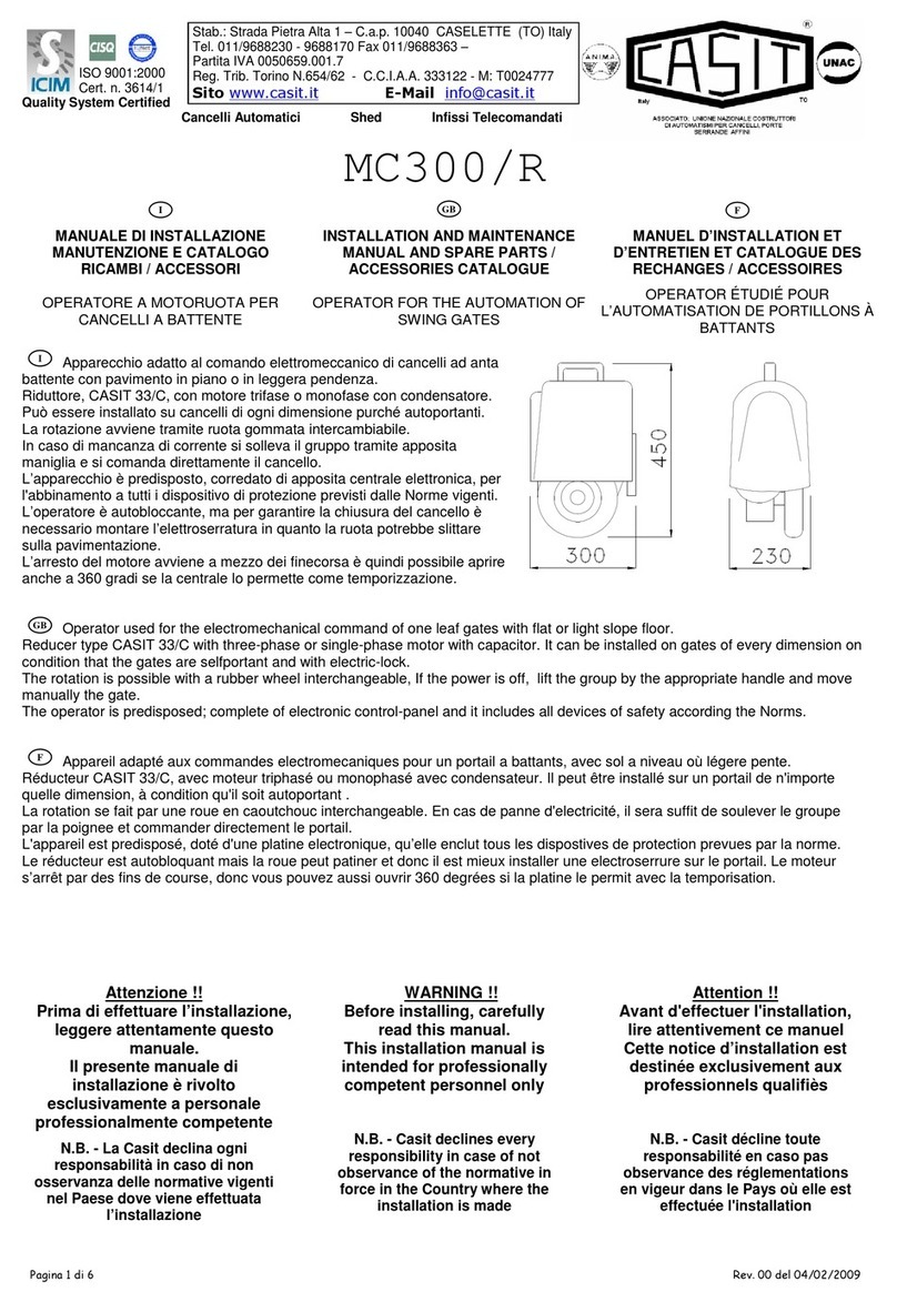
Gli operatori 230Vac monofase della serie Scorry-J sono ideali per motorizzare cancelli scorrevoli su ruote e
binario a terra di larghezza 4-6 -8 mt e peso 500-800 e 1000 kg ad uso residenziale/intermittente. Sono disponbili in
versione senza centrale elettronica a bordo operatore o con centrale.
Sono euipaggiati di finecorsa: elettromecanco a molla +attivatori finecorsa - leverismo con chiave per sblocco
manual di mergenza –piastra di fondazione.
The 230Vac single-phase operators of the Scorry-J series are ideal for motorizing sliding gates on wheels and
ground rail 4-6 -8 m wide and weight 500-800 and 1000 kg for residential / intermittent use. They are available in
the version without electronic control unit on board the operator or with control unit.
They are equipped with limit switches: spring electromechanical + limit switch activators - lever mechanism with key
for manual release of emergency - Foundation plate.
Les opérateurs monophasés 230Vac de la série Scorry-J sont idéaux pour la motorisation de portails coulissants
sur roues et voies au sol d'une largeur de 4-6- 8 m et d'un poids de 500-800-1000 kg pour un usage résidentiel /
intermittent. Ils sont disponibles dans la version sans unité de contrôle électronique embarquée dans l'opérateur ou
avec l'unité de contrôle.
Ils sont équipés d'interrupteurs de fin de course: électromécaniques à ressort + fin de course - mécanisme à levier
avec clé de déblocage manuel d'urgence - Plaque de fondation.
2- Dotazione standard - Packing List (standard)- Équipement standard
No.
Immagine-Picture-Image
Descrizione-Name-Description
Qt.y
1
Operatore
Operator
Operateur
1
2
Chiavi per leverismo sblocco
Manual release key
Clès pour le mécanisme de deverrouillage
2
3
Finecorsa a molla ed accessori
Spring limit switch accessories box
Fin de course à ressort et accessoires
1
4
Attivatori finecorsa
Spring limit switch block
Activateurs de fin de course
1
4-1
Viti M6x10 attivatori finecorsa
Spring limit switch block mounting screw M6X10
vis M6x1 pour activateurs de fin de course
4
5-1
Casit code: SCORRY/SP06
Base metallica a murare
Mounting plate
Base en métal à fixer au sol
1
5-2
Tirafondo M8 per base a murare
Foundation bolt M8
Vis M8 pour base en métal à fixer au sol
4
5-3
Dado M8 per base a murare
Nut M8
Ecrou M8 pour base en métal à fixer au sol
8
5-4
Rosetta Ø8 per base a murare
Flat washer Ø8
Rosette plate Ø8
8
5-5
Grover d.8 per base a murare
Spring washer Ø8
rosette élastique Ø8
4
4 Rev02 del 8 ottobre 2022
3-Accessori opzionali - Optional accessories - Accessoires en option
No.
Immagine-Picture-Image
Descrizione-Name-Description
Qty
1
Cremagliera mod4 30x12 acc.zinc
Steel gear rack 30X12
Cremaillere mod4 30x12 acier galavanisè
4mt
2
Cremagliera mod4 plastica
Nylon gear rack
Cremaillere mod4 en plastique
4mt
3-1
EQLRS2102
ENTRY LEVEL(=C1 model)
Centrale elettronica di comando
Electronic control unit
Unité de contrôle électronique
1
3-2
KEQ214
MEDIUM LEVEL(=C2 model)
Centrale elettronica di comando
Electronic control unit
Unité de contrôle électronique
1
3-3
KEQS08
HIGH LEVEL(=C3 model)
Centrale elettronica di comando
Electronic control unit
Unité de contrôle électronique
1
135 236
270
60
22 55
46
38
127
Z14:51;Z17:57
22
204±0.390±0.3
Dimensioni operatore - Operator size- Dimensions de l'opérateur
4- Modelli e dati tecnici - Models and technical data - Modèles et données techniques
Model
SCORRY500J/C0 *
SCORRY500J/C1
SCORRY500J/C2
SCORRY510J/C1
SCORRY800J/C0 *
SCORRY800J/C2
SCORRY800J/C3
SCORRY1000J/C0 *
SCORRY100J/C3
ATTENZIONE: I modelli contrassegnati con * sono senza centrale elettronica
ATTENTION: Models marked with * are without electronic control unit.
ATTENTION: Les modèles marqués d'un * sont sans platine électronique
Alimentazione Power supply
Puissance
220V/50/60Hz;
110V/60Hz
220V/50/60Hz;
220V/50/60Hz;
Potenza motore -Motor power
Puissance du moteur
280W
380W
Condensatore –Capacitor -
Condensateur
10 Mf
35MF
2,5 Amp
10 Mf
16Mf
Velocità cancello - Speed gate -
Vitesse portail
13m/min
11m/min
Pignone dentato - Toothed pinion
Pignon denté
Z17 mod 4
Z14 mod 4
Peso max cancello Maximum
weight of gate
Poid maximum portail
500 KG
800 Kg
1000 kG
Frequenza utlizzo - Use
frequency
Utilisation
16 manovre / ora –60 manovre / 24 ore
16 maneuvers / hour - 60 maneuvers / 24 hours
16 manœuvres / heure - 60 manœuvres / 24 heures
Peso-Weight-Poid
11,5 kg
12.0 kg
5 Rev02 del 8 ottobre 2022
4.1 Base metallica dimensioni - Size of mounting plate –Base au sol dimensions
( SCORRY/SP06)
107
150
204±0.3
90±0.3
8×10
Φ
4.2 Procedure di installazione - Installation procedures - Procédures d'installation
4.2.1 Analisi peliminari - Preliminary checks - Contrôles préliminaires
Accertarsi che il cancello scorrevole sia installato correttamente, che il binario del cancello sia orizzontale e che il
cancello possa essere spostato manualmente senza problemi prima di installare l'operatore: il cancello deve scorrere
con una forza max di spinta pari a 200 Newton(= 20 kg) ton.
Please make sure that the sliding gate is correctly installed, the gate rail is horizontal, and the gate can be manually
moved smoothly before installing the gate opener:the gate must slide with a maximum thrust force of 200
Newtons (= 20 kg) ton.
Assurez-vous que le portail est correctement installé, que son rail est horizontal et qu'il peut être déplacé
manuellement: la porte doit glisser avec une force de poussée maximale de 200 Newtons (= 20 kg) tonne.
4.2.2 Installazione cavi elettrici - Cable installation –Installation cables electriques
Al fine di garantire il corretto funzionamento del operatore, collocare i cavi del motore e/o della alimentazione in tubi in
PVC separati da quelli per I cavi degli accessori( finecora, fotocellule, ecc)
On order to guarantee the correct operation of the operator, place the motor and / or power supply cables in PVC pipes
separate from those for the accessory cables (limit switches, photocells, etc.)
Afin de garantir le bon fonctionnement de l'opérateur, placez les câbles du moteur et / ou de l'alimentation dans des
tuyaux en PVC distincts de ceux des câbles accessoires (fins de course, cellules photoélectriques, etc.).
4.2.3 Basamento in cemento - Concrete pedestal - Socle en béton
Costruire un piedistallo in cemento di dimensioni 400 mm x 250 mm, profondità 200 mm per il fissaggio dell base
metallica SCORRY/SP06. Assicurarsi che la distanza tra cancello ed operatore sia adeguata e che la base metallica
sia solidamente bloccata nel cemento e che al suo interno fuori escano i tubi in PVC ed i relativi cavi elettrici
Please precast a concrete pedestal with sizes 400mm x 250mm, depth be 200mm or fixing the SCORRY / SP06 metal
base. Make sure that the distance between the gate and the operator is adequate and that the metallic base is firmly
locked in the cement and that the PVC pipes and the relative electric cables come out inside
Construisez une base en béton de 400 mm x 250 mm, d'une profondeur de 200 mm pour la fixation de la base en
métal SCORRY / SP06. Assurez-vous que la distance entre la porte et l'opérateur est adéquate et que la base
métallique est fermement verrouillée dans le ciment et que les tuyaux en PVC et les câbles électriques correspondants
sortent à l'intérieur
6 Rev02 del 8 ottobre 2022
4.2.4 Installazione operatore - Operator installation - installation de l'opérateur
1-Smontare la copertura in plastica del'operatore prima dell'installazione e conservare la reltiva bulloneria di fissaggio;
2-Posizionare l’operatore sulla base metallica( precedemente installata) e portare i cavi elettrici fuori uscenti dalla base
metallica in prossimità del motore, finecorsa, ecc.
3-Fissare l’operatore sulla base metallica con la bulloneria a corredo, Sbloccare l’operatore azionando il leverismo per
il comando manual.
1-Remove the operator's plastic cover before installation and keep the relevant fixing bolts;
2-Position the operator on the metal base (previously installed) and take the electric cables out from the metal base
near the motor, limit switches, etc.
3-Fix the operator on the metal base with the bolts supplied, Release the operator by operating the lever mechanism
for manual release
1-Retirez le couvercle en plastique de l'opérateur avant l'installation et conservez les boulons de fixation
correspondants;
2-Positionnez l'opérateur sur la base métallique (précédemment installée) et sortez les câbles électriques de la base
métallique à proximité du moteur, des fins de course, etc.
3-Fixez l'opérateur sur la base en métal à l'aide des boulons fournis. Libérez l'opérateur en actionnant le mécanisme à
levier pour la commande manuelle
Procedura sblocco manuale - Manual release procedure- Procédure de deverrouillage
Per sbloccare: sbloccare il leverismo con la chiave . Tirare e ruotare di 90 gradi il leverismo. Azionare
manualmente il cancello.
Per bloccare: azionare manualmente il cancello fino a che l’operatore è blocccato. Riportare il leverismo in
posizione e bloccarlo con la chiave
To unlock: Unlock the lever mechanism with a key. Pull and rotate the lever mechanism by 90 degrees.
Manually activate the gate.
To lock: operate the gate manually until the operator is locked. Return the lever to position and lock it with
the key
Pour déverrouiller: déverrouiller le mécanisme de levier avec le clé. Tirez et faites pivoter le mécanisme de
90 degrés. Activer manuellement la porte.
Pour verrouiller: actionner le portail manuellement jusqu'à ce que l'opérateur soit verrouillé. Remettre le
levier en position et le verrouiller avec la clé
Turn on 90°
7 Rev02 del 8 ottobre 2022
4.2.5. Installazione cremagliera - Gear rack installation –Installation cremalliere
1-Fissare la viteria di montaggio sulla cremagliera.
2-Posizionare la cremagliera sull'ingranaggio di uscita( rispettare la distnaza di fig.A) ,quindi saldare i distanziali della
viteria di montaggio sul cancello. Se la cremagliera è il tipo in plastica, fissarla con le viti in dotazione invece di
saldarla. Curare particolarmente il passo della cremagliera usufruendo di 1 spezzone di cremagliera come riferimento.
FIG.B
3-Spostare manualmente il cancello (il cancello deve essere spostato senza intoppi dopo lo sblocco del motore), lo
scorrimento sia libero senza alcun impedimento.
4-Saldare saldamente tutti i diitanziali dele viti di montaggio sul cancello.
5-Accertarsi che tutta la cremagliera sia in bolla ed in linea retta.
FIG.A
FIG. C
1-Fix the mounting screws on the rack.
2-Place the rack on the output gear, then weld the spacers of the assembly screws on the gate. If the rack is the
unplastic type, fix it with the supplied screws instead of welding it. Particularly take care of the pitch of the rack using 1
piece of rack as a reference. FIG.B
3-Manually move the gate (the gate must be moved smoothly after unlocking the motor) to check if there is a space
between rack and output gear, as shown in Figure A.
4-Firmly weld all of the gears of the mounting screws on the gate.
5-Make sure that all the rack is level and in a straight line.
6-Pull the gate after installation, make sure that the sliding is free without any hindrance
1-Fixez les vis de montage sur le rack.
2-Placez la crémaillère sur le pignon de sortie, puis soudez les entretoises des vis de montage sur le portail. Si le rack
est du type non plastique, fixez-le avec les vis fournies au lieu de le souder. Faites particulièrement attention au pas du
rack en utilisant 1 morceau de rack comme référence. fig.B
3-Déplacez manuellement le portail (le portail doit être déplacé en douceur après le déverrouillage du moteur) pour
vérifier s'il y a un espace entre le rack et le pignon de sortie, comme illustré à la figure A.
4-Soudez fermement tous les engrenages des vis de fixation sur le portail.
5-Assurez-vous que tout le rack est de niveau et en ligne droite.
6-Tirez la porte après l'installation et assurez-vous que le coulissement est libre sans aucune entr
8 Rev02 del 8 ottobre 2022
Attenzione - Warnings - Attention
Per garantire la sicurezza, installare gli arresti meccanici di sicurezza su entrambe le estremità delle guide per evitare
che il cancello fuoriesca dalla guida. Prima di installare l’operatore, assicurarsi che siano presenti arresti meccanici di
sicurezza e che siano adeguatamente dimensionati e solidamente fissati
To ensure safety, install safety stop blocks on both ends of the rails to prevent the gate from running out of the rail.
Before installing the main engine, make sure that the safety stop blocks are in place and whether it has the function of
preventing the gate from running out of the rail or safety range.
Pour assurer la sécurité, installez les butées de sécurité mécaniques aux deux extrémités des guides afin d’empêcher
le portail de sortir du guide. Avant d'installer l'opérateur, assurez-vous qu'il existe des butées de sécurité mécaniques,
qu'elles sont correctement dimensionnées et solidement fixées
4.3.4 Regolazione finecorsa - Limit switch adjustment - Réglage de fin de course
1. Verificare che la distanza dal operatore al cancello(Fig.D) e che iI gioco pigone/crmagliera siano confom.i.
2.Aprire il cancello manulamente e posizionare sulla cremagliera l’attivatore del finecorsa apre(fig. D)
3. Chiudere il cancello manulamente e posizionare sulla cremagliera l’attivatore del finecorsa chiude(fig. D)
4.Azionare elettricamente l’operatore e regolare,se necessita, gli attivatori dei finecorsa per femare il cancello nelle
posizioni apre/chiude desiderate.
1.Check that the distance from the operator to the gate (Fig. D) and that the rack and pinion clearance are confom.
2.Open the gate manually and place the limit switch activators on the rack (fig. D)
3. Close the gate manually and position the limit switch activator on the rack (fig. D)
4. Move electrically the operator and adjust, if necessary, the limit switch activators to stop the gate into the desired
open / close positions.
1. Vérifiez que la distance entre l'opérateur et le portail (Fig. D) et que le jeu de la crémaillère et du pignon sont
corrects.
2.Ouvrez le portail manuellement et placez l’activateur du fin de course sur le cremalliere (fig. D).
3. Fermer le portail manuellement et positionner l’activateur de fin de course sur le cramaillere (fig. D)
4. Actionner électriquement l'opérateur et régler, si nécessaire, les activateurs de fin de course pour arreter le portail
dans les positions d'ouverture / fermeture souhaitées
M6×10M6×10 M6×10M6×10
Fig D
9 Rev02 del 8 ottobre 2022
LAY-OUT elettrico - Electric LAY-OUT - LAY-OUT électrique -
ITA
GB
F
E
n° fili x sezione
n° wires x section
n° cables x section
n° câbles y sección
1)
Interruttore di linea
Power supply switch
Interructeur general
Interructor general
3 x 1,5
2)
Operatore +
centrale elettronica
Operator +
ECU
Operateur +
Centrale Electornique
Motor Redudtor
4 x 1,5 (motor)
3 x 0,5 (limit switch)
4)
Selettore a chiave
Key switch
Selecteur a clef
Selector de llave
2 x 0,5
5)
Pulsantiera
Push button
Boutton poussoir
Pulsadores
3 x 0,5
6)
Lampeggiante
Flashing light
Clignotant
Lampara intermitente
2 x 1,5
7)
Fotocellula
Photocells
Cellules photo
Celulas-foto electricas
Rx (4 x 0,5) Tx(2 x 0,5)
8)
Costa sensibile
Safety edge
Barre palpeuse
Costa (Goma) Sensible
2 x 1
9R
X)
Fotocellula a pila
(ricevitore)
Battery photocell
(receiver)
Cellule photo à batterie
(recepteur)
Foto-celula a pilas
(receptor)
4 x 0,5
9T
X)
Fotocellula a pila
(trasmettitore)
Battery photocell
(transmitter)
Cellule photo à batterie
(emetteur)
Foto-celula a pilas
(receptor)
2 x 0,5
11)
Antenna
Aerial
Antenne
Antena
RG S8
14)
Cremagliera
Rack
Cremaillere
Cremallera
17)
Pilastrino
Pillar
Potelets
Poste
10 Rev02 del 8 ottobre 2022
DICHIARAZIONE DI CONFORMITA’
DECLARATION OF CONFORMITY
DECLARATION DE CONFORMITE’
(in accordo alla guida 22ISO/IEC ed alla norma
EN 45014)
(Complie with the guide 22ISO/IEC et
EN 45014)
(Suivant guide 22ISO/IEC et
EN 45014)
Io sottoscritto
I undersigned
Je soussigne’
RAMELLA CARLO
legale rappresentante della Ditta
legal representative
representant
CASIT SAS, Via Pietra Alta 1, 10040 Caselette (To) Italy.
DICHIARO CHE I SEGUENTI APPARATI:
I DECLARE THAT THE FOLLOWING
APPARATURE :
DECLARE QUE LES SUIVANTS PRODUITS:
OPERATORI PER PORTA SCORREVOLE
OPERATORS FOR SLIDING DOOR
OPERATEURS POUR PORTE COULISSANT
Modello
Model
Models
SCORRR500J SCORRY510J SCORRY800J SCORRY1000J
E’ CONFORME AI REQUISITI DI EMC
DEFINITI DALLE SEGUENTI NORME
THE FOLLOWING COMPLIE WITH THE
REQUIREMENT OF EMC AND THE
STANDARDS:
EST CONFORME AUX PRINCIPES DE EMC
DEFINIS PAR LES NORMES SUIVANTES:
EN55014-1 ;EN6100-2-2 ; EN6100-3-3 ;EN55014-2 ;EN6100-4-2 ; EN6100-4-3 ; EN6100-4-5 ; EN6100-4-4 ; EN6100-4-6 ; EN4100-4-11 ;
EN60335-1 ; EN60335-A11 ; EN62233
L’apparato e’ stato provato nella configurazione
tipica di installazione e con periferiche conformi
alla Direttiva EMC.
The apparatus is tested in the typical
configuration of installation and the Directive
EMC.
Le produit a ete teste’ dans sa configuration
typique d’installation et avec peripheriques
conformes a la directive EMC
L’apparato sopra descritto soddisfa i requisiti
della :
The described apparatus satisfies the
requirement of:
LE Produit susdite satisfait les principes de:
DIRETTIVA EMC 89/336/EEC
sopra specificati, sulla base dei risultati delle
prove e delle relative valutazioni descritte nei
rapporti di prova al ns.interno:
Results on the base of the tests and the relative
records results in our archives:
avant specifies, en relation au resultats des
tests et valutations descripts dans les rapports
des test chez nos archives:
DICHIARAZIONE CE DI CONFORMITÁ PER
MACCHINE
DECLARATION CE OF CONFORMITY FOR
MACHINERY DIRECTIVE
DÉCLARATION CE DE CONFORMITÁ POUR
MACHINES
(Direttiva 89/392 CE, Allegato II, parte B)
(Directive 89/392 CE, Annex II, B)
Il prodotto è costruito per essere incorporato in
una macchina o per essere assemblato con altri
macchinari per costruire una macchina
considerata dalla Direttiva 89/392 CE, come
modificata; E non contiene dispositivi di
sicurezza intrinsechi. Non è quindi consentito
mettere in servizio il prodotto fino a che la
macchina in cui sarà incorporata o di cui diverrà
componente sia stata identificata e ne sia stata
dichiarata la conformità alle condizioni della
Direttiva 89/392 CE e alla legislazione nazionale
che la traspone vale a dir fino a che il prodotto di
cui alla presente dichiarazione non formi un
complesso unico con la macchina finale.
The product is constructed to be incorpored into
machinery or to be assembled with other
machinery to constitute machinery covered by
Directive 89/392 CE , as amended; And it does
not contain safety devices intrinsic. So, it is
proibithed put in service the product until that
the machine in which it will be incorporated or of
which will become component has been
identified and of the conformity to the conditions
of the Directive has been declared 89/392 CE
and to the national legislation that transposes it
is worth to say until that the product of which to
the present declaration not forms an only
complex with the final machine
Le produit est fabrique pour etre incorpore dans
une machine,ou pour etre assemble avec autres
composants pour fabriquer une machine selon la
directive 89/392CE et modification.don est
interdit de mettre en service le produit avant que
la machine dans laquelle le produit sera
incorpore,soit identifiee et declaree conforme a
la Directive 89/392 CE et a les normes
nationales.,de facon que le produit de cette
declaration soit integre a la machine finale.
Caselette, 20 settembre 2019
Firma e timbro, signature and stamp, tampon et signature

This manual suits for next models

11

Other Casit Gate Opener manuals

Casit MC300/IMB User manual

Casit

Casit MC300/IMB User manual

Casit EQ2006 User manual

Casit

Casit EQ2006 User manual

Casit MC300/R Instruction Manual

Casit

Casit MC300/R Instruction Manual

Casit MC300/IM WINCH User manual

Casit

Casit MC300/IM WINCH User manual

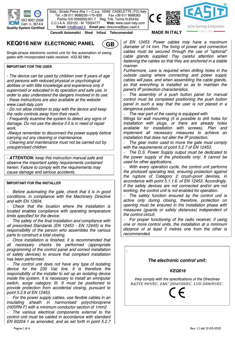
Casit KEQ016 User manual

Casit

Casit KEQ016 User manual

Casit EQ212 User manual

Casit

Casit EQ212 User manual

Casit ROLLY MC300/RC Instruction Manual

Casit

Casit ROLLY MC300/RC Instruction Manual

Casit SLIDY/S User manual

Casit

Casit SLIDY/S User manual

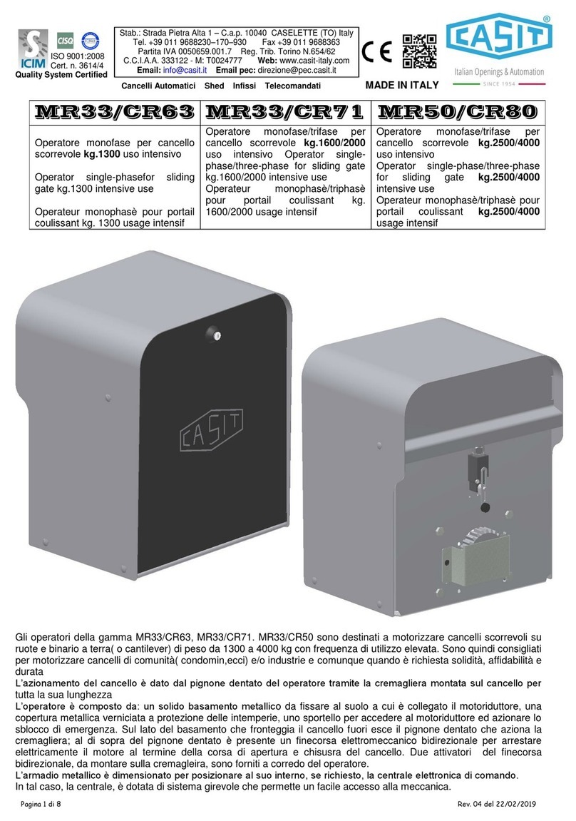
Casit MR33/CR63 User manual

Casit

Casit MR33/CR63 User manual

Casit MLA 400 User manual

Casit

Casit MLA 400 User manual

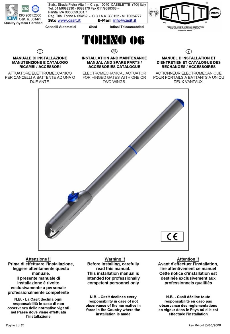
Casit TORINO 06 Manual

Casit

Casit TORINO 06 Manual

Casit AF0051/ML Instruction Manual

Casit

Casit AF0051/ML Instruction Manual

Casit EQ2009 User manual

Casit

Casit EQ2009 User manual

Popular Gate Opener manuals by other brands

Rossi DZ GHT9 Installation

Rossi

Rossi DZ GHT9 Installation

GATEMASTER 900 HD installation manual

GATEMASTER

GATEMASTER 900 HD installation manual

CAME F1024 installation manual

CAME

CAME F1024 installation manual

IQ Gate Systems IQ-500 Installation and instruction manual

IQ Gate Systems

IQ Gate Systems IQ-500 Installation and instruction manual

Life Optimo OP3 Instructions and warnings for installation, use and maintenance

Life

Life Optimo OP3 Instructions and warnings for installation, use and maintenance

vds AMICO 400DG Technical installation manual

vds

vds AMICO 400DG Technical installation manual

Genius Falcon 14 installation instructions

Genius

Genius Falcon 14 installation instructions

Nice RO 1000 Instruction manual and spare parts catalogue

Nice

Nice RO 1000 Instruction manual and spare parts catalogue

SEA Cougar 270 manual

SEA

SEA Cougar 270 manual

AES iGate 1200 quick start guide

AES

AES iGate 1200 quick start guide

SOMFY Passeo 500 manual

SOMFY

SOMFY Passeo 500 manual

Biketronics CribClicker BT385 installation guide

Biketronics

Biketronics CribClicker BT385 installation guide

vds LINEAR-11 Technical installation manual

vds

vds LINEAR-11 Technical installation manual

HySecurity HTG 320-8 Installation and maintenance manual

HySecurity

HySecurity HTG 320-8 Installation and maintenance manual

PPA DZ HUB R Technical manual

PPA

PPA DZ HUB R Technical manual

Autoglide CABRI-20P user manual

Autoglide

Autoglide CABRI-20P user manual

Toors BFT ARGO installation manual

Toors

Toors BFT ARGO installation manual

tousek ST 61A Connection and installation manual

tousek

tousek ST 61A Connection and installation manual

manuals.online logo
manuals.online logoBrands
  • About & Mission
  • Contact us
  • Privacy Policy
  • Terms and Conditions

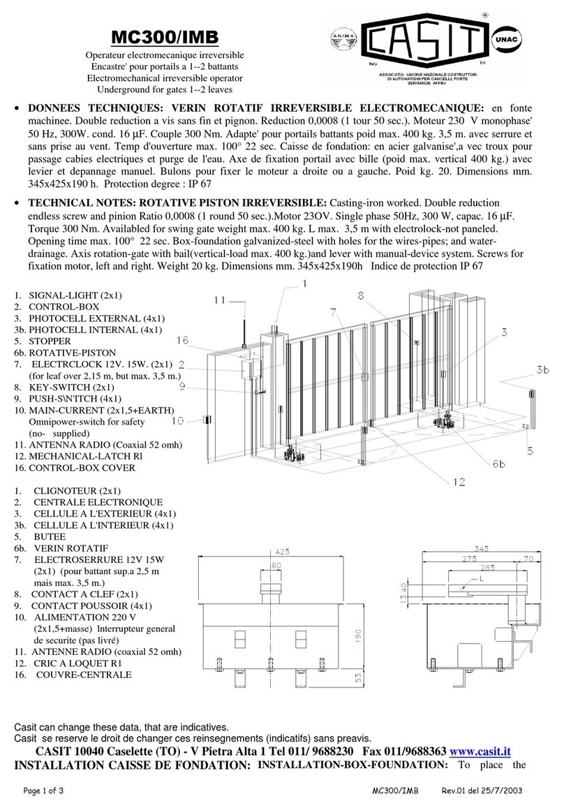
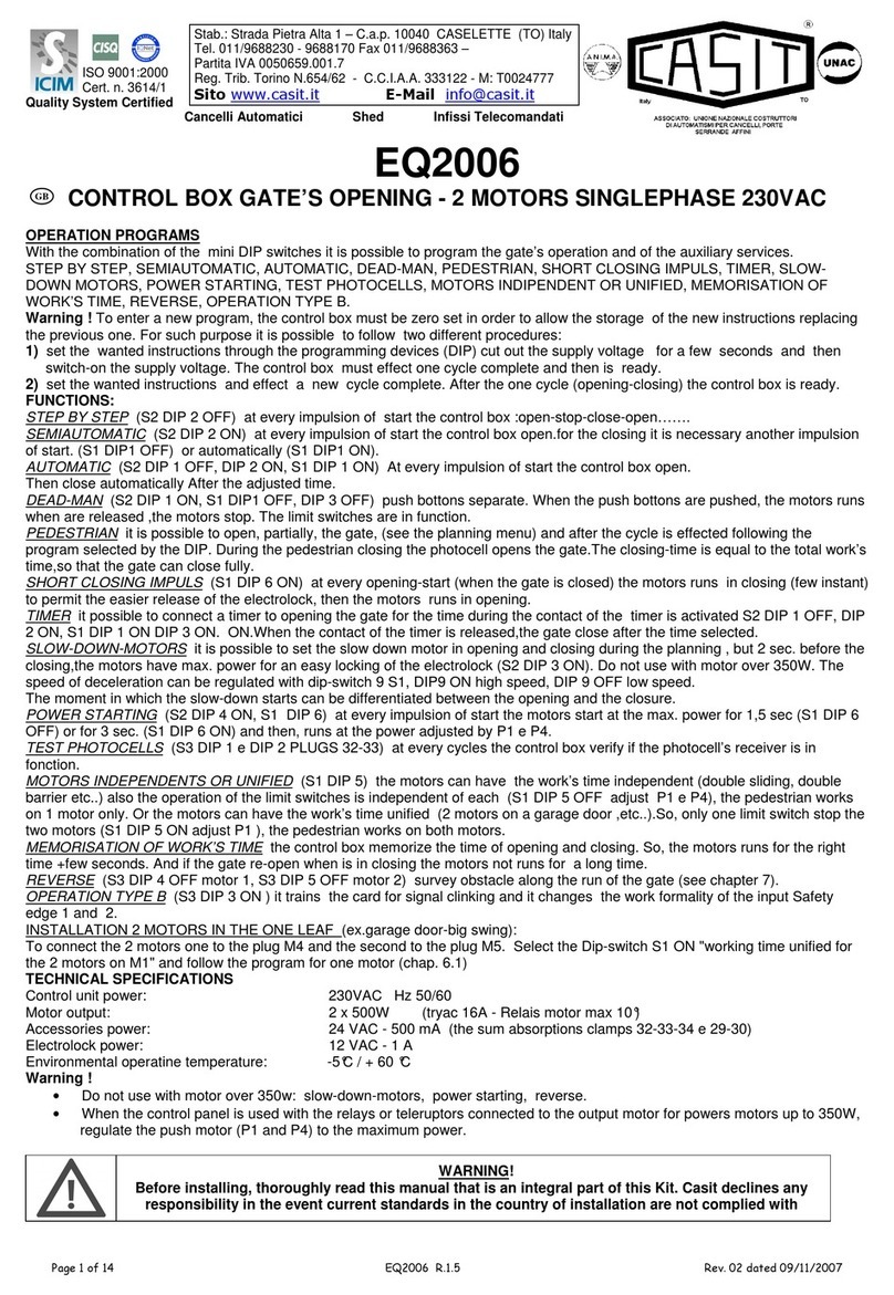
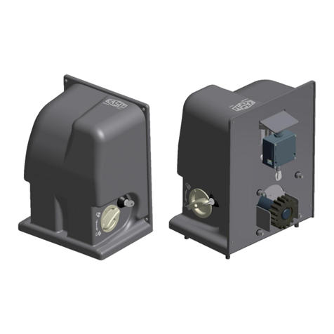
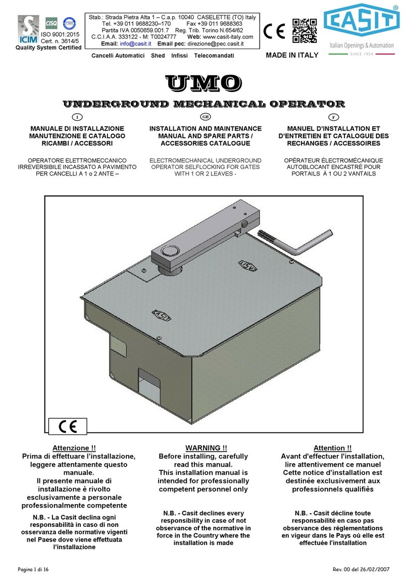
Copyright 2025 Manuals.Online. All Rights Reserved.