7
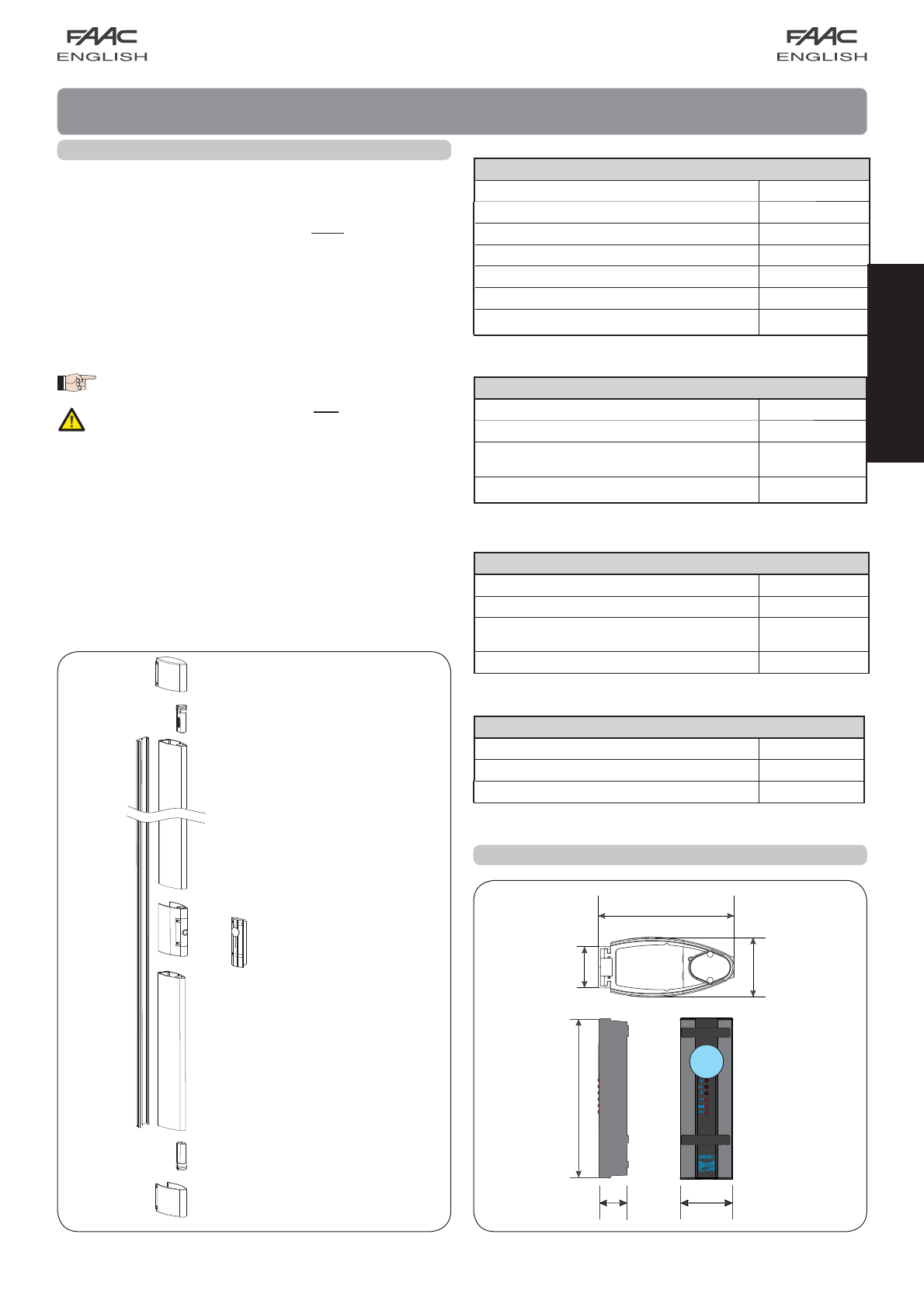
45 mm.
135 mm.
L2
L1
TX1
TX2
ENGLISH
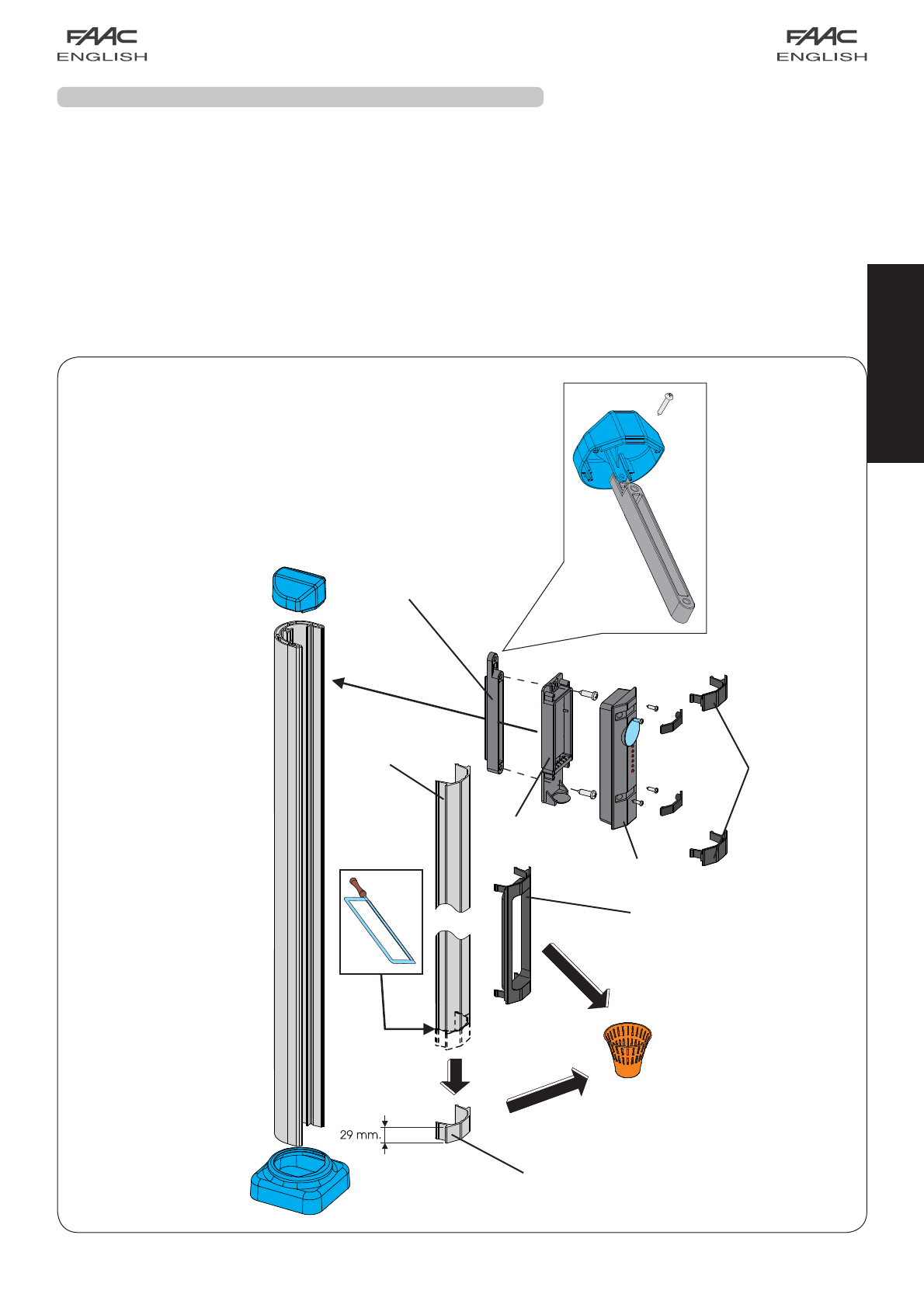
5.3.2 Installing the rubber profiles and the
receiver-transmitter
Fit the batteries (supplied standard) in the top and bottom
transmitters, observing correct polarity as indicated on the
plastic container (TX1 and TX2 Fig. 7).
• Fit the transmitters on the ends of the rubber profiles, observing the
direction indicated in Fig. 7, with the lens on the front detection
border of the edge.
• Fit the bottom rubber profile, sliding it downward along the support
profile, and taking it in contact against the lower support
spacer.
• Remove the front panel of the receiver-transmitter (ref.
Fig. 7B).
Place thebatteries (suppliedstandard) in thereceiver-transmitter,
respecting polarity (Fig. 7A).
• Reinstall the front panel (ref. a Fig. 7B), fastening all the sup-
plied
screws, and, when you install the front panel, make sure that the
lens on the front panel flashes briefly to confirm correct installation.
Fig. 8
• Fit the receiver-transmitter so that the logo is not overturned, sli-
ding it downward along the support profile, until the rigid coupling
is fully inserted in the rubber profile.
Check if the rubber profile and the receiver-transmitter are in
contact with each other.
• Fit the top rubber profile, sliding it downward along the support
profile, making sure that the rigid coupling is fully inserted in the
rubber profile.
Check if the rubber profile and the receiver-transmitter are in
contact with each other.
• Secure the support spacer in the top hole which had been left
free.
5.3.3 Installing the closing caps
Fit the closing caps, checking if they are in contact with the rubber
profiles, and secure them with the self-tapping screws (supplied
standard) in the pre-drilled holes.
Fig. 9
Position the fixed receiver so that the lens on the front panel (Fig. 8
ref. ) is at a height from 50 to 55 cm off the ground. (HT see Fig. 5).
• Separate the bottom (Fig. 8 ref. ) from the front panel (Fig.8
ref. ).
• Mark, for drilling the holes, the two screw securing points (Fig. 8
ref ) - screws not supplied.
• Using adequate screws and expansion plugs, secure the bottom
of the receiver (Fig. 8 ref. ).
•To route the cables, use the facility in the lower part of the
receiver.
• Make the electrical connections as shown in Chap. 6, using the
rubber cable gripper (Fig.8 ref ).
• Assemble the front cover (Fig. 8 ref. ) to the bottom (Fig. 8 ref.
), using the supplied screws (Fig. 8 ref. ), supplied standard.
• Finish installing the receiver, by fitting the rubber protective de-
vices (Fig. 8 ref. ) on the screws.
Fig. 7BFig. 7A
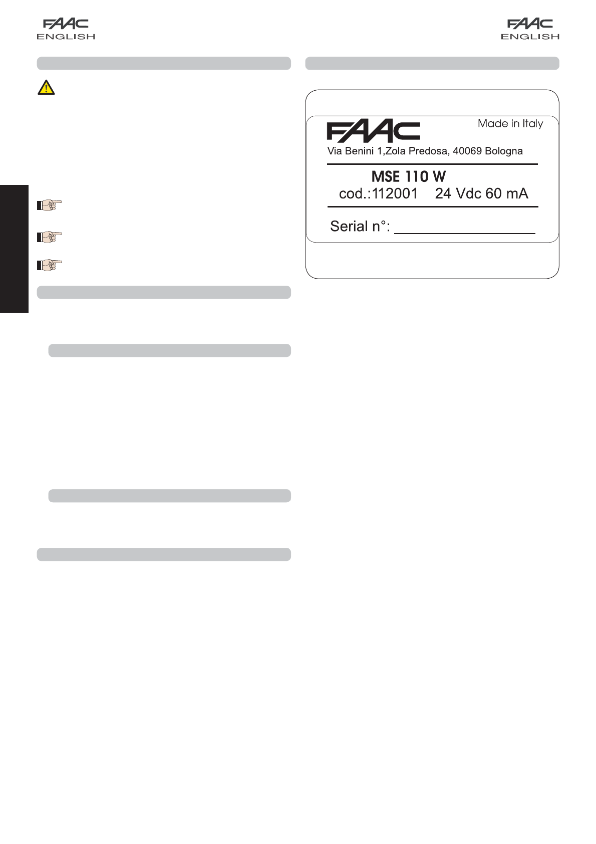
5.3.4 Installing the fixed receiver
ATTENTION before installing the fixed receiver, take a note of
the serial number, on the data-plate on the rear, as indicated
in Chap.8 FINAL OPERATIONS.
Fig. 7