Entrya D22S User manual

Facila neXt
D22S/D22F
Installation and User manual

2
All texts and images in this manual are protected by copyright and intellectual property
of ENTRYA TECHNOLOGIES BVBA.
V.101120210942
Index
Precautions 2
Usage 2
Description 3
Specications 3
Normal Usage and Usage of the keypad 4
Creating and changing codes 4-5
Index Codes 6
Conguration of the door station 7
Mounting 8
Electrical installation 9
Electrical installation of an analogue camera 9
Electrical installation of two door stations 9
Electrical installation of more door stations 10
Electrical installation of an electric lock 10-11
CE Declaration of conformity 12
Usage
• The manufacturer is not liable for damage caused by other use. The risk is borne exclusively by
the operator.
• The appliance may only be in a technically perfect condition and according to the regulations
used, also in compliance with the safety and hazard guidelines and the installation and operating
instructions.
• Faults that make safe use impossible must be remedied immediately.
Precautions
Read this manual carefully before installing or using the appliance.
Entrya Technologies BVBA is not responsible for incorrect installation and non-compliance with local
electrical and building regulations.
Entrya Technologies BVBA cannot be held liable for damage and
malfunctions arising from failure to observe the installation and operating instructions.
Save all parts and this manual for later use.
Always disconnect the appliance from the power supply before starting work and secure it against
restarting switch.
Never use a damaged appliance.
It is not permitted to change parts other than described in this manual.
If a fault cannot be resolved, contact a qualied installer. Do not open the device!

3
87 mm
188 mm
All texts and images in this manual are protected by copyright and intellectual property
of ENTRYA TECHNOLOGIES BVBA.
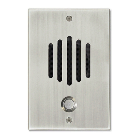
Description
camera
state indicator
speaker
connectors
microphone
keypad
call button
Specications
Power Supply 30V DC +/- 2V
Camera 900 TVL, wide angle 150° (H) x 80° (V)
Degree of protection IP54
Working temperature -40°C - +65C°
Dimensions D22S : 87 x 188 x 30 mm
D22F : 120 x 220 x 50 mm
LK-JP

4
Code
#
#
#
#16 ... 35
Nr
All texts and images in this manual are protected by copyright and intellectual property
of ENTRYA TECHNOLOGIES BVBA.
V.101120210942
Code for Lock 1
Use parameters 16 up to 35 for conguring up to 20 codes for Lock 1.
4 - 12 numbers
Enter the Mastercode (default: 1234) and conrm with #.
When the code is correct, two beeps will be played.
Choose the desired parameter and conrm with #.
The door stations sounds two beeps to conrm.
Enter the desired code and conrm with #.
The door station conrms the input with one beep.
Parameter Code
16 1
17 2
18 3
... ...
34 19
35 20
Important!
The menu will close automatically after 10 seconds of inactivity.
Usage of the keypad
Usage in a Villa system
Usage in an appartment system
Press the code and conrm with # to activate the lock. Push * to cancel.
Push the call button to start a call.
Press the desired call number and conrm with the call button.
Create or change codes
Create up to 40 codes to activate the desired lock outputs.
Mastercode

5
#
#
#
#
#
#
56 ... 59
36 ... 55
#
#
#60 ... 63
All texts and images in this manual are protected by copyright and intellectual property
of ENTRYA TECHNOLOGIES BVBA.
Temporary code Lock 1
Use parameters 56 up to 59 for conguring 4 temporary codes for Lock 1.
Code for Lock 2
Use parameters 36 up to 55 for conguring up to 20 codes for Lock 2.
4 - 12 numbers
4 - 12 numbers
Enter the Mastercode (default: 1234) and conrm with #.
When the code is correct, two beeps will be played.
Enter the Mastercode (default: 1234) and conrm with #.
When the code is correct, two beeps will be played.
Choose the desired parameter and conrm with #.
The door stations sounds two beeps to conrm.
Choose the desired parameter and conrm with #.
The door stations sounds two beeps to conrm.
Enter the desired code and conrm with #.
The door station conrms the input with one beep.
Enter the desired code and conrm with #.
The door station conrms the input with one beep.
Parameter Code
56 1
57 2
58 3
59 4
Parameter Code
36 1
37 2
38 3
... ...
54 19
55 20
Important!
Temporary codes are only valid for one time and are deleted 60 seconds after usage.
A temporary code can still be used during 60 seconds after usage.
Mastercode
Mastercode
Mastercode
Temporary code Lock 2
Use parameters 60 up to 63 for conguring 4 temporary codes for Lock 1.
4 - 12 numbers
Enter the Mastercode (default: 1234) and conrm with #.
When the code is correct, two beeps will be played.
Choose the desired parameter and conrm with #.
The door stations sounds two beeps to conrm.
Enter the desired code and conrm with #.
The door station conrms the input with one beep.
Parameter Code
60 1
61 2
62 3
63 4
Important!
Temporary codes are only valid for one time and are deleted 60 seconds after usage.
A temporary code can still be used during 60 seconds after usage.

6
All texts and images in this manual are protected by copyright and intellectual property
of ENTRYA TECHNOLOGIES BVBA.
V.101120210942
Lock 1
Code Name
1
2
3
4
5
6
7
8
9
10
11
12
13
14
15
16
17
18
19
20
Lock 2
Code Name
1
2
3
4
5
6
7
8
9
10
11
12
13
14
15
16
17
18
19
20
Index Codes
Save the codes in a clear overview on a safe location.
Mastercode
Mastercode
Mastercode
1
2
3
#
#
#
##
#
#
#
#
07
07
07
Delete codes
Delete all permanent codes
Delete all temporary codes
Delete all codes

7
Mastercode
Mastercode
Mastercode
Mastercode
Mastercode
Mastercode
Mastercode
Mastercode
Mastercode
Mastercode
Mastercode
Mastercode
1 - 5
1 - 4
#
#
#
#
#
#
#
#
#
#
#
#
#
#
#
#
#
#
#
#
#
#
#
#
#
#
#
#
#
#
#
#
#
#
#
01
02
03
04
14
10
11
15
12
05
06
00
All texts and images in this manual are protected by copyright and intellectual property
of ENTRYA TECHNOLOGIES BVBA.
Conguration Door station
Congure Mastercode
Conguring Nightlight of the keypad
Set Unlocking Time Lock 2
Set Unlocking Time Lock 1
Set delay of the unlocking
Set the talking volume
Set address of the door station
Set Call Tone
Set System Type
Lock that is activated with manual button
Play sound when unlocking
Restauring Factory Settings
Default: 1234
Default: ON
Default: 7sec
Default: 7sec
Default: 0sec
Default: 3
Default: 1
Default: ON
Default: Villa
Default: Both
Default: Uit
New mastercode (4-12)
0: ON / 1: OFF
1: 0.5sec / 2: 1sec / ... / 20: 10sec
1: 0.5sec / 2: 1sec / ... / 20: 10sec
1: 0.5sec / 2: 1sec / ... / 20: 10sec
0: ON / 1: OFF
0: Villa / 1: Appartment
0: Lock 1 / 1: Lock 2 / 2: Both
0: O / 1: On
Restore Mastercode
Open the menu ‘Special fonctions’ in the indoor monitor M71(W).
Restore Mastercode for address:
1: 8001 2: 8002 3: 8003 4: 8004
Restore all mastercodes: 8000

8
All texts and images in this manual are protected by copyright and intellectual property
of ENTRYA TECHNOLOGIES BVBA.
V.101120210942
Mounting
Mount the appliance on a at surface and use the supplied screws or use mounting materials adapted
to the surface. Connect the wiring and select the required settings. Determine the height of the instal-
lation according to the situation.
Important:
• Mount the outpost so that no bright light (e.g. street lighting or sunlight)
• shines directly into the camera lens, otherwise the contrast of the image will be nega-
tive
• aected.
• Protect the device from vibrations and falls.
• Disturbances in the picture or sound may occur if the unit or wiring is mounted too
close to an electromagnetic eld. For example: microwave oven, TV, computer, power
1. Drill holes in the wall and attach the
mounting frame.
2. Connect the wiring and set the correct
settings.
3. Attach the rubber ap.
4. Secure the entrance panel with the
screw at the bottom.
• Make an opening in the wall with the
following dimensions:
104 (W) x 205 (H) x 45 (D)
• Attach the ush-mounted box and run
the cables through the cable gland.
• Attach the outdoor unit to the
ush-mounted box with the supplied
screws.

9
Ω
BUS(DS) BUS(IM) BUS BUSBUS BUS
BUS
CV-AP- CV+AP+
CCTV
GNDCOM C
GND
CCTV
Ω
BUS(DS) BUS(IM) BUSBUS BUS
2x 0.75mm² 60m Facila BUS 2x 0.75mm² 60m
2x 0.75mm² 30m SVV 2x 0.75mm² 30m
All texts and images in this manual are protected by copyright and intellectual property
of ENTRYA TECHNOLOGIES BVBA.
Electrical installation of two door stations
Electrical installation of an analogue camera
COAX-cable
Address 1 Address 2
COAX-cable
Electrical Installation
Attention!
The maximum length of the wiring is limited. The use of cables other than those specied
may aect the maximum length of the wiring or cause malfunctions. It is not allowed to
place cable with parallel wires (not twisted) over long distances next to other cables. This
can cause disturbances in the picture and sound. Always use Facila BUS cable with twisted
pairs without shielding.
Attention!
Switch on terminating resistor / impedance switch on accessories or indoor stations with
symbol Ω.

10
Ω
BUS(DS) BUS(IM) BUS BUS
BUS BUSBUS BUS
BUS
Mastercode 1 - 4# ##11
SD41
BUS
CV-AP- CV+AP+
CCTV
GNDCOM C
1 2 3
1 2 3
All texts and images in this manual are protected by copyright and intellectual property
of ENTRYA TECHNOLOGIES BVBA.
V.101120210942
Electrical installation of more door stations
Address 1 Address 3Address 2 Address 4
Set address of the door station Default: 1
Electrical installation of a lock
Schematic for Lock 1 with internal power supply
Exit-button for manual unlocking
Max. 12V DC, 300mA
The lock is not active in standby (NO)
The lock is active in standby (NC)
LK-JP

11
BUS
CV-AP- CV+AP+
CCTV
GNDCOM C
1 2 3
1 2 3
COM C
All texts and images in this manual are protected by copyright and intellectual property
of ENTRYA TECHNOLOGIES BVBA.
Schematic for Lock 2 with external power supply
Power
Drukknop voor manuele slotontgrendeling
Max. 12V CC, 6A
The lock is not active in standby (NO)
The lock is active in stancby (NC)
Mastercode # ##05
Unlock Lock with manual Exit-button
LK-JP
Default: both
0: Lock 1 / 1: Lock 2 / 2: Both
Max. 12V DC
P
o
s
s
i
b
l
e
t
o
c
o
n
n
e
c
t
d
i
r
e
c
t
l
y
o
n
t
h
e
p
u
s
h
b
u
t
t
o
n
-
i
n
p
u
t
o
f
a
g
a
t
e
o
p
e
r
a
t
o
r

12
https://www.entrya.com/ce
All texts and images in this manual are protected by copyright and intellectual property
of ENTRYA TECHNOLOGIES BVBA.
V.101120210942
CE Declaration of Conformity
This manual suits for next models
1
Table of contents
Other Entrya Intercom System manuals
