enua Wallmount User manual

Enua
Wallmount
Installation guide
enua.no
ENG/NOR
Authorized personnel only
10001

Product overview 3
4
Mounting set
5
Technical specifications
7
Safety instructions 6
Safety instructions for use
8-10
Installation guide
Assemble wall bracket
Start configuration
11
11
12
Table of contents
Light description over charging station
IMPORTANT:
Read carefully before use. Keep for future reference.
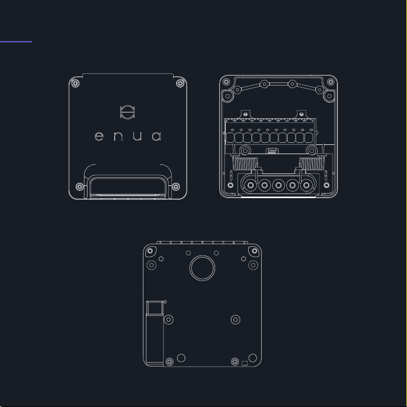
1. Product overview
Inside of wall bracket
Backside of wall bracket
Front cover
ENG 3
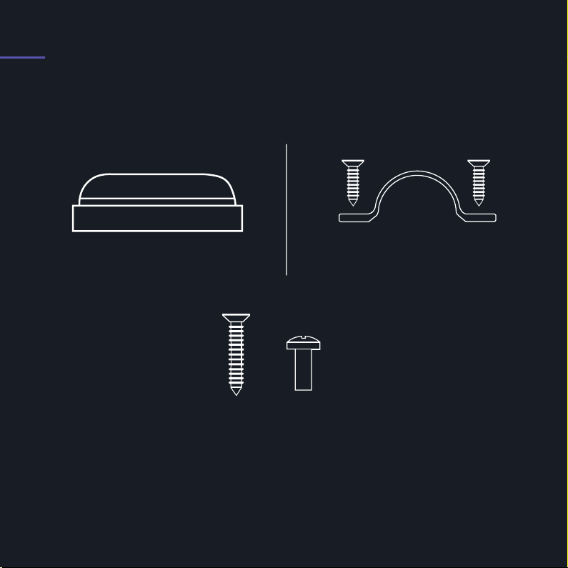
2. Mounting set
Nipples Cable clamp
Mounting screws
x4
2x 1x
ENG 4
ENG 5
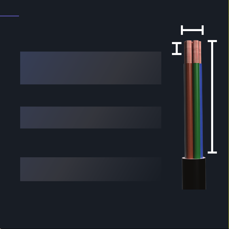
3.Technical Specifications
Operating temperature:
Max. 80A fuse on
installation circuit
- 30 til +50C
Weight:
Wire cross-section:
Cable dimension:
Length of cable:
Length of wire:
2.5-10mm2
10-20mm
200-270mm
19mm
0,6kg
Dimensions (mm) 143 x 135 x 76 (H x B x D)
Installation circuit
230VAC ± 10 %
400VAC ± 10 %
TN, IT og TT
Installation network voltage
7.4kW at 32 A/1-phase IT/TN
22kW at 32 A/3-phase (TN-network)
12.7kW at 32 A/3-phase (TN-network)
Max. power and charging outlets
IK9 impact protection
UL94 Fire classification
Equipment class I
Overvoltage category III
IP44 for indoor and outdoor use
Protection:
Overcurrent protection according to IEC 60364-4-43
RDC-DD 6mA according to IEC 62955
EVSE Mode 3 IEC 61851-1
Protection built into charging station:
General
200-270 mm
2.5-10mm
19 mm
Table of contents
Languages:
Popular Automobile Accessories manuals by other brands


ULTIMATE SPEED
ULTIMATE SPEED 279746 Assembly and Safety Advice

SSV Works
SSV Works DF-F65 manual

ULTIMATE SPEED
ULTIMATE SPEED CARBON Assembly and Safety Advice

Witter
Witter F174 Fitting instructions

WeatherTech
WeatherTech No-Drill installation instructions

TAUBENREUTHER
TAUBENREUTHER 1-336050 Installation instruction