Envirco Hospi-Gard User manual

www.envirco.com
Operation Manual
HOSPI-GARD®
IsoClean®
And
IsoClean® UV

HOSPI-GARD® ISOCLEAN® and ISOCLEAN® UV
Operation Manual
i
CAUTION AND WARNINGS
READ AND SAVE THESE INSTRUCTIONS
CAUTION: To reduce the risk of fire, electrical shock or injury to persons, observe the
following:
A. Installation work and electrical wiring must be done by a qualified person(s) in accordance with
all applicable codes and standards, including fire-rated construction.
B. When cutting or drilling into a wall or ceiling, do not damage electrical wiring or other hidden
utilities.
C. Service to this equipment should be performed by authorized technicians trained and
experienced in performance evaluation and maintenance of clean air equipment. However,
certain procedures are outlined in this manual that can be performed by the owner.
D. Before servicing the unit, switch power off at service panel and lock service panel to prevent
power from being switched on accidentally, and follow proper procedures as necessary.
E. Use this unit only in the manner intended by the manufacturer. If you have questions, please
contact:
ENVIRCO CORPORATION FEDDERS INTERNATIONAL
Envirco Office Headquarters
5601 Balloon Fiesta Parkway N.E. No. 268 Xi Zang Road (M)
Albuquerque, New Mexico 87113 Haungpu District
U.S.A. Shanghai 200001
Tel : (505) 345-3561 PRC
Fax : (505) 345-8875 Tel : (86) 512 6258 7180
Email: info@envirco.com Fax : (86) 512 6258 0035
TRION LTD. FEDDERS INTERNATIONAL, INC.
The Cavendish Centre DP Computers Building
Winnall Close 128 Joo Seng Road #05-01
Winchester, Hampshire, SO23 0LB, UK Singapore 368356
Tel : 44 1962 840465 Tel : 65 286 0995
Fax : 44 1962 828619 Fax : 65 286 0859
Email: info@trion.co.uk
Hospi-Gardis a registered trademark of ENVIRCO Corporation
IsoClean CM® is a trademark of ENVIRCO Corporation
US Patents 4,560,395 and 5,470,363. Other patents issued and pending in foreign countries

HOSPI-GARD® ISOCLEAN® and ISOCLEAN® UV
Operation Manual
ii
TABLE OF CONTENTS
TITLE PAGE
1.0. Introduction ............................................................................................................................... 1
1.1. Description ...........................................................................................................................................1
1.2. Features...............................................................................................................................................1
1.3. Applications..........................................................................................................................................2
2.0. Installation ................................................................................................................................. 3
2.1. Unpacking Instructions.........................................................................................................................3
2.2. Assembly .............................................................................................................................................3
2.3. Initial Start-Up ..............................................................................................3
3.0. Operating Procedures ............................................................................................................... 4
3.1. Initial Set-Up ........................................................................................................................................4
3.2. Speed Adjustment................................................................................................................................4
3.3. Airflow Indicator ...................................................................................................................................4
3.4. Recirculation Mode ..............................................................................................................................5
3.5. Partial Exhaust/Recirculation Mode (Negative Pressure)....................................................................6
3.6. Total Exhaust Mode (Negative Pressure)............................................................................................6
3.7. Negative Pressure ...............................................................................................................................7
4.0. Maintenance and Service .......................................................................................................... 9
4.1. Parts Identification ...............................................................................................................................9
4.2. Cleaning the Unit ...............................................................................................................................11
4.3. Prefilter Replacement ........................................................................................................................11
4.4. Removal of Front and Rear Panels ...................................................................................................12
4.5. HEPA Filter Replacement..................................................................................................................12
4.6. Power Cord ........................................................................................................................................13
4.7. On/Off Switch.....................................................................................................................................13
4.8. Speed Control Switch ........................................................................................................................13
4.9. Air Pressure Switch............................................................................................................................13
4.10. Capacitor............................................................................................................................................14
4.11. Pilot Light ...........................................................................................................................................14
4.12. Motor..................................................................................................................................................14
4.13. Motor/Blower Lubrication ...................................................................................................................14
4.14. Relocating a Contaminated Unit ........................................................................................................14
4.15. Unit Decontamination.........................................................................................................................15
4.16. UV Light Tube Replacement..............................................................................................................17
5.0. Troubleshooting ...................................................................................................................... 18
5.1. Inoperative Air Flow ...........................................................................................................................18
5.2. Low Air Flow ......................................................................................................................................18
5.3. High Air Flow......................................................................................................................................18
5.4. Excessive Contamination ..................................................................................................................18

HOSPI-GARD® ISOCLEAN® and ISOCLEAN® UV
Operation Manual
iii
6.0. Wiring Diagram ........................................................................................................................ 19
6.1. Hospi-Gard®IsoCleanWiring Diagram............................................................................................19
6.2. Hospi-Gard®IsoCleanUV Wiring Diagram......................................................................................20
7.0. Specifications .......................................................................................................................... 21
7.1. IsoClean®...........................................................................................................................................21
7.2. IsoClean®UV .....................................................................................................................................21
8.0. Replacement Parts .................................................................................................................. 22
9.0. Airflow Measurement and Testing.......................................................................................... 24
10.0. Appendix .................................................................................................................................. 25
11.0. Limited Warranty ..................................................................................................................... 26

HOSPI-GARD® ISOCLEAN® and ISOCLEAN® UV
Operation Manual
Page 1
INTRODUCTION
1.0. Introduction
1.1. Description
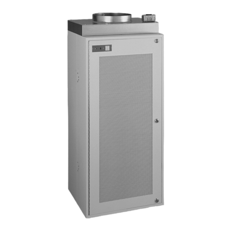
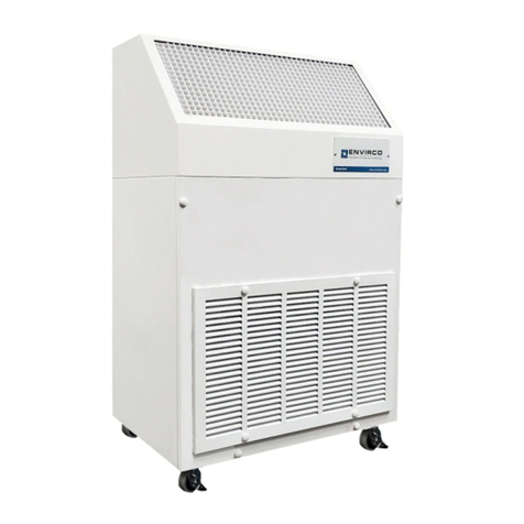
The Hospi-GardIsoClean®and IsoClean®UV are portable, self-contained high-
efficiency particulate air (HEPA) filtration system specifically designed to provide a high-
velocity airflow pattern from the top face grille that creates a sweeping action to remove
airborne particulate. In addition to recirculating clean air, it can simultaneously exhaust
air out of the room to create negative pressure. An optional 8-inch exhaust collar is
available to convert the IsoClean®to a complete exhausting system.
Air enters the module through the intake grille located on the lower section of the unit.
The air is evenly drawn by the blower first through a prefilter and then through a HEPA
filter. The HEPA filter is 99.99% efficient at removing particles 0.3 microns and larger.
The air moves at a volume of 550 cubic feet per minute (CFM) on low, 700 CFM on
medium and up to 800 CFM on high to carry away airborne particulate generated by
activities within the room.
The IsoClean®UV offers the added benefits of ultraviolet irradiation of the particulate
caught on the HEPA filter surface and in the air prior to recirculation back into the room.
1.2. Features
•The Hospi-GardIsoClean®can be used as a total recirculating air system, as a total
air exhaust system (using the optional 8-in. exhaust collar) or as a split system with
partial air recirculation and partial air exhaust.
•The Hospi-GardIsoClean®can easily and economically convert a standard room
into a negative pressure, patient isolation room.
•Provides 27 air changes per hour in a typical patient room of 18 feet x 12 feet x 8 feet.
•The three-speed adjustable airflow control allows effective use in a variety of room
sizes.
•High discharge air velocity with a high-to-low airflow pattern assures adequate “reach”
and air circulation, preventing “short circuiting.”
•Quiet operation. 52 dBA at low, 56 at medium and 60 at high speed measured 30 in.
from face of unit.
•HEPA filter and prefilter are easy to replace.
This manual suits for next models
2
Table of contents
Other Envirco Air Cleaner manuals
