Eoslift E20V User manual

E20V
Operating Instructions
Scale
Pallet
Truck
Hotline: 400-626-9090
Tel: +86 573 8622 9999
Fax: +86 573 8622 2900

Esteemed users:
For proper and safe operation of the products, before
using the products, be sure to read the operating
instructions carefully and retain them properly for
future reference.
The operator needs to have proficient operation skills.
The operator has responsibility to carefully understand
the performance and safety rules of the pallet truck.
If you have any doubts during the application, please
don't hesitate to contact Eoslift.
E20V Series Scale Pallet Trucks

Ⅰ.Technical parameters 01
Ⅱ. Safety rules 02
Ⅲ.Installation of handles 03
Ⅳ.Adjusting the finger grip handle 04
Table of contents
Ⅵ.Appendix 13
Ⅶ.Troubleshooting 14
Ⅸ.Parts list 17
Ⅴ.Operating instruction
05
Ⅷ.Transport, loading, test run and storage 16
E20V Series Scale Pallet Trucks

Technical parameters
01 02
Safety rules
Rated capacity
Load center
Dead-weight
Wheel material
Maximum error
Maximum fork height
Minimum fork height
Steering wheel
Load-bearing wheel
Overall fork width
Fork length
Length of the truck
Minimum turning radius
Type of battery
Battery capacity
Model E20V
kg
mm
mm
mm
mm
mm
mm
mm
kg
mm
mm
mAh
2000
600
130
PU/NYLON
0.05
190/200
75/85
Φ180×50
Φ80×70
560/685
1150/1220
1580/1650
1325/1395
Button cells
2x900
H
H1
B
L
L1
R
The pallet truck is only applicable to indoor use and the application environment must meet the following
conditions:
Free from rainwater or corrosion of harmful gases;
Room temperature of -20°C~+40°C;
Relative ambient humidity <90%;
and Requirements for ground: hard, anti-skid and level without barriers.
Before using the pallet truck, the operator must read the operating instructions and the warning labels on
the truck body carefully.
Do not use this truck on the muddy ground.
Do not operate the pallet truck unless you are fully familiar with it and have been authorized to do so.
Do not operate the pallet truck unless you have carefully checked its condition. Pay special attention to the
wheels, the handle assemblies, the truck frame, the unloading plate, etc. To pull the truck, always move the
finger grip control handle into the middle position. This makes the handle easier to move and reduces the
rebounce of the handle by the small piston. This also preserves the hydraulic seals and the piston
components. A long service life can be expected.
Do not carry or lift passengers.
The operator shall wear safety shoes and gloves for protection.
While the goods are being transported, all people should stay 600mm away from the truck frame.
Overload is prohibited.
Do not use the truck in a potentially flammable and explosive atmosphere.
Do not use the truck as a vehicle jack.
Do not use the truck during strong wind forces.
Do not use the truck on places insufficiently illuminated.
Under special conditions or in special locations, the operator should be careful while operating the pallet
truck.
E20V Series Scale Pallet Trucks
%

Installation of handles
03 04
Adjusting the finger grip handle
1.Make sure the chain on the handle
is in this position shown in the picture.
2.Push the handle shaft through the
holes,Fix it with the spring pin.
3.Put the chain through the hole on the shaft.
4.Fix the chain in the slot of the
unloading plate.
5.Pull the shaft from the hole. Then
the assembly is complete.
On the handle of this pallet truck, you can find finger grip control handle(1-1) which can be regulated in
three positions :
Lifting-set the control handle at lower position
Middle position: set the control handle at middle position
Lowering: set the control handle at upper position. The handle moves back to the middle position when
released.
1
2
3
However if the truck cannot operate normally under three positions, you can adjust them according to the
following steps:
①If the forks elevate while pumping in the Middle position, turn the adjusting nut (2-4) on the adjusting bolt
(2-3) or screw (2-6) clockwise until pumping action does not raise the forks and the finger grip control handle
works properly Middle position .
1-1
Upper
Middle
Lower
2-3
2-4
2-6
E20V Series Scale Pallet Trucks
② If the forks descend while pumping in the Middle position, turn the screw(2-6) or nut(2-6) counter
clockwise until the forks stop descending.
③ If the forks do not descend when the finger grip control handle (1-1) is in the Lowering position, turn
the nut (2-4) or screw (2-6) clockwise until raising the control handle lowers the forks. Then check the
Middle position according to items and ② to make sure the nut (2-4) and screw(2-6) are in the proper①
position.
④ If the forks do not elevate when the finger grip control handle is in the Lifting position, turn the nut
(2-4) or screw (2-6) counterclockwise until the forks elevate. Then check the function of the Lowering
position and Middle position according to items ,②and③ is normal.①

IP 53
1.Using the Scale Pallet Truck
The truck shall be correctly used to ensure accurate weighing. The following conditions are prohibited in
the application.
Operating Instructions
05 06
2.Normal weighing mode
2.1Operating panel
Figure 2-1 Operating panel in Normal Weighing Mode
Weight display
Unit of measurement
Battery level
Zero
On/Off back light
Unit switching
Backlight cursor
Dynamic cursor
Tare cursor
Net weight cursor
Zero cursor
1
2
3
4
5
6
7
8
9
10
11
Note: Abbreviations for the following keys:
Zero key--“0”key
Tare removal key--“T”key
Unit switch key - “U” key
ON/OFF key - “P” key
TARE
E20V Series Scale Pallet Trucks

07 08
2.2 Display
If any cargo is placed on the frame, its weight will be displayed after 1 second; once “ dynamic cursor”
disappears, value as displayed on the screen will be the weight of the cargo.
2.3 Key function.
Display function
Zero key (“ 0” ) ---Reset instrument readings within the permissible range.
Tare removal key ( “T” )---Current weight is taken as the tare weight for tare removal based
on the gross weight; whereas the instrument is to be switched over to the net weight for
display. Recover the tare weight as deducted at the net weight, and switch the instrument
to the gross weight for display.
Unit switch key ( “U” )---It is for cyclic switching of measurement unit among KG, T, OZ and
LB, representing “ kilogram” , “ ton” , “ ounce” and “ pound” respectively.
ON/OFF key (“ P”) ---Once this key is pressed and held for 2 seconds under ON status, “ -----”
is to be displayed on the screen before power-off; press the key for a while to turn on the back
light in the back light mode. Press the key for a while for start-u
Combination key function
“U” key + “0” key - Factory reset
“U” key + “T” key - enter the parameter setting mode
①
②
3.Parameter setting mode
3.1Operating panel
Figure 3-1 Operating panel in parameter setting mode
1Input value
Calibration unit
Input cursor
Option selection
Option confirmation
Location switching
Option cancellation
2
3
4
5
6
7
Press “ U” key and “ T” key simultaneously in normal display mode to enter the parameter setting mode when
“SETUP” is displayed on the screen. The function of the individual key is as follows:
“0” key - option selection
Press “ T” key to confirm entry into parameter setting mode; press “ U” key to cancel parameter setting
to enter normal display mode.
Operating Instructions E20V Series Scale Pallet Trucks
“T” key - option confirmation.
“U” key——option cancellation
“P” key - digit switching in calibration mode.

09 10
3.2Default unit setting
Default unit of the system is kilogram (KG).
The first option in parameter setting mode is default unit setting; when “ UNIT” is displayed on the screen,
press “ T” key to confirm entry into unit setting mode; press “U” key for cancellation to proceed with next
setting.
Once default unit setting is confirmed, press “0”key repeatedly for cyclic switching among the units as
displayed on the right side of screen: “ KG” , “ T” , “ OZ” and “ LB” , representing “kilogram” , “ ton” ,
“ ounce” and “ pound” respectively; press “ T” key to confirm the setting, and proceed with next setting.
3.3Back light mode setting
Default back light mode of the system is OFF; shortly press “ P” key to turn on the back light when back
light cursor is displayed on the screen in back light mode.
Once default unit setup is completed, proceed with setting of back light; when “ BLMOD”is displayed on
the screen, press “ T” key to confirm back light mode setting; press “U” key for cancellation to proceed
with next setting.
Once back light mode setting is confirmed, press “ 0” key for cyclic switching of items displayed on the
screen; “ BL ON” and “ BL OFF” refer to Back Light On and Off respectively; press “T” key to confirm
setting, and proceed with next setting.
3.4Auto Power-off Time Setting
Default auto power-off time of the system is 5 minutes when cargoes remain unchanged.
Proceed with auto power-off time setting once back light mode setting is completed; when “ POWTM” is
displayed on the screen, press “ T” key to confirm entry into auto power-off time setting; press “ U” key
for cancellation to proceed with next setting.
Once auto power-off time setup is confirmed, press “ 0”key for cyclic switching among 1-9, representing
auto power-off time (in minute); press “ T” key to confirm the setup, and proceed with next setup.
1. Press “U” key and “T” key simultaneously
for Setup mode in normal mode.
4.Calibration
Operating Instructions E20V Series Scale Pallet Trucks
2 .Press the “T” key to enter the setup
mode
3. Press the “U” key to skip the “unit
settings”
4. Press the “U ” key to skip the “back
light setting”
5. Press the “U” key to skip the “power
-off time setting”
6. Make sure that here is no cargo on
the frame, and Press “T” key to confirm
calibration.

11 12
7-1. Press “0”key to input values. 7-2. Press “ P " key to adjust the input
digit bit.
25kg
5.Battery replacement
Diagram for disassembly of battery cover
Battery holder
Battery cover
1
2
The instrument uses 2 CR2447 button cells.
As shown in the Figure, slide down instrument battery cover to remove the used battery for replacement;
put the new battery into the battery holder, and then close the battery cover.
6.Routine maintenance
Please check the oil level every six months and change the oil every twelve months. 32 # hydraulic oil is
recommended, with total volume of about 0.5 liters.
Replace the battery in time if power monitoring icon as displayed is blank or data displayed is
indistinct.
It is better not to put the instrument into prolonged outdoor operation in case of rain and snow;
prolonged exposure of instrument to the sunshine is strictly prohibited.
It is applicable to clean the instrument shell with soft and clean cloth in combination with routine
washing solvent; never use industrial solvent for cleaning or directly spray it on the instrument
surface.
It is recommended that users check the instrument and sensor regularly to ensure its accuracy
during use.
7-3. Press “0”key to input value of
corresponding digit bit.
7-4. Example: Calibration with 25KG
counterweight.
8. Complete input, and Press “T” key
for confirmation.
9. Calibration is deemed to be completed
once “CALOK” is displayed on the screen.
E20V Series Scale Pallet Trucks
Operating Instructions

13 14
Item
Description of items displayed on the screen
BLMOD
CALBN
CALOK
CANCEL
FAIL
OUTRG
PMODE
POWTIME
RESET
SS CK
SS OK
SSERR
SETUP
TARE
TR ER
UNTARE
UNIT
ZERO
ZR ER
Backlight mode setting
Calibration
Calibration OK
Cancel parameter setting
Plant calibration failed
Out of range
Plant calibration mode
Auto power-off time setting
Factory reset
Sensor check
Sensor OK
Sensor error
Parameter setting
Tare removal
Tare removal error
Untare
Unit setting
Zero
Zero error
Troubleshooting
1.System halt
This product has received strict testing before delivery and no system halt will occur under
normal conditions. Please remove the battery, and refit it again to recover its normal operation
in case of system halt.
2.Start-up failure
2.1Turn off the power supply. Disassemble the gauge outfit, and use a voltmeter to measure
battery voltage; if the voltage is below 3.5V, it means that battery voltage is extremely low,
which may result in start-up failure; replace the old battery with new one in this case.
2.2Disassemble the gauge outfit, and use a voltmeter to measure battery voltage; if the
voltage is over 3.5V, just check if the red-black connecting line between battery module and
instrument panel is disconnected.
2.3Other problems. Please contact professionals for testing of panel if power supply is normal.
3.Abnormal display
3.1If the sensor is proved to be normal through test, just press the unit switching key to see if
the data displayed is normal.
3.2Sensor connection: If display of instrument reading is abnormal, just turn off the instrument
and turn on it again to check screen display; if “SSERR” is displayed on the screen following
display of “SS CK”, it means that connection of sensor is abnormal; in this case, it is necessary
to check if connection between the sensor and instrument panel is normal before contacting
professionals to check if sensor output is normal.
3.3Calibration: If abnormal data is still displayed by the instrument following unit switching,
just use “unit switching” and “tare removal” in combination to enter the parameter setting mode,
and recalibrate at the final setting option (for details, please refer to page 10).
4.Truck failure
The forks cannot
be lifted to max.
height
The hydraulic oil is
insufficient
The hydraulic oil has
impurities
Adjusting nut(2-4) or
adjusting screw(2-6) in
wrong positions
Air enters into the cylinder
Seals damaged
1
2
Fault Possible cause Action
No.
Appendix
Description
E20V Series Scale Pallet Trucks
The forks cannot
be lifted
The hydraulic oil is
insufficient Add the hydraulic oil
Add the hydraulic oil
Change hydraulic oil
Adjust nut(2-4) or adjusting
screw(2-6)
Put the finger grip handle in
the upper position and press
the handle dozens of times
Replace the damaged seals
with new seals

15 16
Note: Do not attempt to repair the pallet truck unless you are trained in the professions.
Piston rod or the frame is
deformed resulting from
overloading or cargo
slanting to one side
The forks was kept in raised
position for extended period
of time, then the piston rod
is exposed to the air and gets
rusted , which blocks the
motion of the piston
Adjusting nut(2-4) or
adjusting screw(2-6) in
wrong positions
The forks cannot
be lowered
Seals damaged
Parts damaged
5
The forks
descended without
operation
3
4Oil leakage
The handle shall be detached before loading the truck.
The handle should be fixed stably in case sliding and damages and transported by fork truck or crane.
Before shipment, the operator should first check the truck weight, in order to choose the right crane.
When the truck is unloaded, the operator shall look out for safety around to ensure slow landing of the
truck.
If the truck is transported with the forklift truck, the forklift shall lift and lower it slowly to keep the balance
of the truck.
The truck shall be commissioned according to the following function tests: steering, traveling, braking
and combined functions with rated capacity.
When a truck is inoperative, the cargoes (if applicable) shall be removed with proper tools, the truck
shall be transported out of the working zone with a proper way.
When the truck will be shut down and in storage for a long time, the storage environment shall be kept
dry and clean, with forks lowered to their lowest position.
If the truck has to be transported for a long distance, it should be packed in the wooden pallet in order
to avoid collision during transportation.
Replace the related parts of
the cylinder or the frame with
new ones
Keep the forks at the lowest
position while not in use, and
keep piston rods lubricated in
time
Adjust nut(2-4) or adjusting
screw(2-6)
Replace the damaged
seals with new seals
Replace the damaged
parts with new parts
Impurities in the oil cause
the valve to be unable to
close tightly
Seals damaged
Adjusting nut(2-4) or
adjusting screw(2-6) in
wrong positions
Change hydraulic oil
Replace the damaged
seals with new seals
Adjust nut(2-4) or
adjusting screw(2-6)
Troubleshooting Transport, loading, test run and storage E20V Series Scale Pallet Trucks

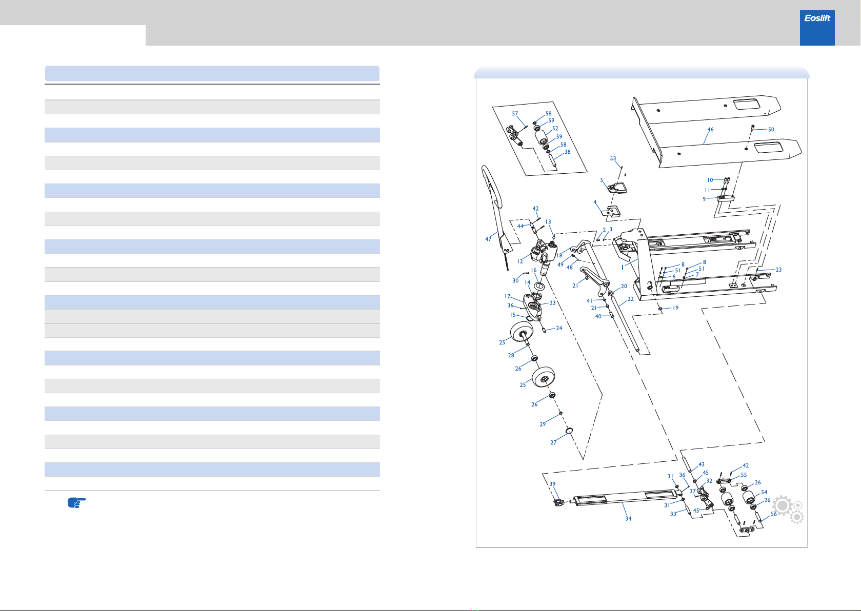
17 18
1
2
3
4
5
6
7
8
9
10
11
12
13
14
15
16
17
18
19
20
21
22
23
24
25
26
27
28
WC02000192
WC02000207
WC02000204
WC04000001
WC04000002
WC01000006
WC02000194
WC02000209
WC02000193
WC02000208
WC02000006
WC02000007
WC02000011
WC02000160
WC02000120
WC02000013
WC02000082
WC02000005
WC02000205
WC02000022
WC02000010
WC02000195
WC02000196
WC02000075
WC02000019
WC02000018
WE06000002
WE06000003
WE06000001
WC02000024
WC02000025
WC02000027
WC02000026
WC02000028
Frame (560 × 1150), 5012
Frame (685 × 1220), 5012
Metal protective shell (E20V), 5012
ValueScale outfit assembly
Cylinder assembly, galvanized
Left push rod (560 × 1150), 5012
Left push rod (685 × 1220), 5012
Right push rod (560 × 1150), 5012
Right push rod (685 × 1220), 5012
Small wheel carrier, black
Rocker, galvanized
Wheel shaft, galvanized
Nylon wheel φ74 × 70, white
Long shaft(540)
Long shaft(685)
Connecting rod assembly (540), black
Connecting rod assembly (685), black
Push rod connecting shaft, galvanized
Shaft
Washer, galvanized
Washer
JB7940.4, Push-fit type grease nipple 6
Connecting bracket, galvanized
Sliding bearing 29×25×25
Sliding bearing 18×16×15
GB3452.1,O-ring φ5×1.8
GB301, thrust ball bearing 51111
1
1
1
4
1
1
1
2
4
4
4
1
1
12
2
2
4
4
3
1
2
4
10
2
4
1
1
1
Gb308, Steel ball S18
GB894.1,Circlip for shaft 52,blackening
Dust cover, galvanized
Bolt pin 2, galvanized
Bolt pin, galvanized
Connecting base, galvanized
GB894.1,Circlip for shaft 16,blackening
Fork cover(560 × 1150), 5012
Fork cover(685 × 1220), 5012
Bowl-shaped concave washer for sensor
Bowl-shaped convex washer for sensor
Screw, M12 × 60
GB893.1,Circlip for hole 25,blackening
Nylon wheel φ180 × 50, white
Big wheel shaft, galvanized
GB894.1,Circlip for shaft 20,blackening
Big wheel cover, black
Big wheel cover, white
Connecting shaft, galvanized
Handle, black
Iron cable clip
R type cable clip6.5
GB95,Plain washer 5,galvanized
GB95,Plain washer 5,galvanized
Washer 53 × 31.8 × 3.5
WC02000020
WE07000003
WC02000015
WC02000012
WC02000014
WC02000190
WE07000002
WE03000001
WE05000001
WE03000009
WE03000007
WE05000006
WC02000191
WC02000206
WC02000202
WC02000198
WC02000201
WE07000001
WC02000199
WC02000078
WC02000017
WE07000004
WC02000016
WC02000076
WE06000004
WC02000004
WC02000003
WC02000200
WC02000197
WE03000006
WE05000004
WE05000004
WC02000774
29
30
31
32
33
34
35
36
37
38
39
40
41
42
43
44
45
46
47
48
49
50
51
52
53
54
55
56
57
58
1
1
1
2
2
2
2
1
1
2
8
8
1
4
4
4
2
2
1
2
2
1
1
1
2
2
6
4
2
4
E20V Series Scale Pallet Trucks
1TA pressure sensor 1TA assembly,
cable length: 130cm
Iron-core PU wheel φ74 × 70,
bright red PU, black iron core
GB276,Deep groove ball bearing 6204,
two-side shielded
GB879.1,Spring type straight pin 5×26,
blackening
GB879.1,Spring type straight pin 5×28,
blackening
GB879.1,Spring type straight pin 5×32,
blackening
JB7940.2, Angle hydraulic grease
nipple M6
GB70.1, Hexagon socket head cap screw
M6 × 16, galvanized
GB93,Normal type spring lock washer 6,
galvanized
GB70.1, Hexagon socket head cap screw
M4×16, galvanized
GB70.1, Hexagon socket head cap screw
M12×35, galvanized
GB93,Normal type spring lock washer 12,
galvanized
Aluminium-core PU wheelφ180×50,
bright red PU
GB879.1,Spring type straight pin 8×45,
blackening
GB818,Pan head screw with cross recess
M5×12,galvanized
Parts list · Frame(85)
Qty.
NO. Parts number Description Qty.
NO. Parts number Description

19 20
1
2
3
4
5
6
7
8
9
10
11
12
13
14
15
16
17
18
19
20
21
22
23
24
25
26
27
28
29
30
31
32
WC02000851
WE03000001
WE05000001
WC02000204
WC04000001
WC02000200
WC02000197
WE03000006
WC04000002
WE03000007
WE05000006
WC01000011
WC02000020
WC02000028
WE07000003
WC02000015
WC02000018
WC02000205
WE07000001
WC02000024
WC02000025
WC02000082
WE06000003
WC02000014
WC02000199
WC02000078
WC02000022
WC02000016
WC02000076
WC02000017
WE07000004
WE06000004
WC02000196
WC02000846
Frame, 5012
Metal protective shell (E20V), 5012
ValueScale outfit assembly
Iron cable clip
R type cable clip 6.5
Pressure sensor
Cylinder assembly, galvanized
GB308, Steel ball S18
GB301, thrust ball bearing 51111
GB894.1,Circlip for shaft 52,blackening
Dust cover, galvanized
Connecting bracket, galvanized
Connecting rod assembly, black
GB893.1,Circlip for hole 25,blackening
Sliding bearing 29×25×25
Sliding bearing 18×16×15
Long shaft
Bolt pin, galvanized
Nylon wheel φ180 × 50, white
Big wheel cover, black
Big wheel cover, white
Big wheel shaft, galvanized
GB894.1,Circlip for shaft 20,blackening
Washer, galvanized
Small wheel carrier, black
E20V Series Scale Pallet Trucks
GB818,Pan head screw with cross recess
M5×12,galvanized
GB70.1, Hexagon socket head cap screw
M6 × 16, galvanized
GB93,Normal type spring lock washer 6,
galvanized
GB70.1, Hexagon socket head cap screw
M12×35, galvanized
GB93,Normal type spring lock washer
12, galvanized
GB879.1,Spring type straight pin
5×28,blackening
Aluminium-core PU wheelφ180×50,
bright red PU
GB276,Deep groove ball bearing 6204,
two-side shielded
GB879.1,Spring type straight pin 8×45,
blackening
Qty.
NO. Parts number Description
Parts list · Frame(85) Parts list · Frame(75)
1
1
1
1
1
2
2
6
4
8
8
1
1
1
1
1
1
1
2
2
4
1
4
2
2
10
2
1
2
1
4
2
21 22
E20V Series Scale Pallet Trucks
Push rod connecting shaft, galvanized
Right push rod, 5012
Left push rod, 5012
JB7940.4, Push-fit type grease nipple 6
Single wheel shaft, galvanized
Connecting base, galvanized
Bolt pin 2, galvanized
GB894.1,Circlip for shaft 16,blackening
Shaft
Connecting shaft, galvanized
Washer
Fork cover, 5012
Handle, black
GB3452.1,O-ring φ5×1.8
Screw, M12 × 40
GB95,Plain washer 5,galvanized
Nylon wheel φ74 × 93, white
Nylon wheel φ74 × 70, white
Rocker, galvanized
Wheel shaft, galvanized
Washer
WC02000010
WC02000850
WC02000849
WC02000019
WE06000002
WC02000073
WC02000190
WC02000012
WE07000002
WE06000001
WC02000195
WC02000004
WC02000075
WC02000218
WC02000003
WC02000027
WC02000026
WC02000847
WE05000004
WC02000074
WC02000118
WE03000009
WC02000160
WC02000120
WC02000007
WC02000011
WE06000001
WC02000075
WC02000022
33
34
35
36
37
38*
39
40
41
42
43
44
45
46
47
48
49
50
51
52*
53
54
55
56
57*
58*
59*
2
1
1
3
2
2
2
2
2
10
2
1
4
1
1
1
1
4
6
2
2
2
2
2
2
4
4
GB879.1,Spring type straight pin
5×26,blackening
GB879.1,Spring type straight pin
5×32,blackening
Iron-core PU wheel φ74 × 70, bright red PU,
black iron core
JB7940.2, Angle hydraulic grease nipple M6
Iron-core PU wheel φ74 × 93, bright red PU,
black iron core
GB879.1,Spring type straight pin 5×32,
blackening
GB276,Deep groove ball bearing 6204,
two-side shielded
GB70.1, Hexagon socket head cap screw
M4×16, galvanized
Note:Marked with "*"are single wheel parts
Qty.
NO. Parts number Description
Parts list · Frame(75)

23 24
1
2
3
4
5
6
7
8
9
10
11
12
13
14
15
16
17
18
19
20
21
22
23
24
25
WC02000170
WC02000157
WC02000060
WC02000036
WC02000061
WC02000059
WC02000058
WC02000035
WC02000045
WC02000046
WC02000038
WC02000071
WC02000037
WC02000044
WC02000039
WC02000064
WC02000063
WC02000042
WC02000041
WC02000043
WC02000040
WC02000049
WE06000005
WE03000003
WE04000003
WC01000046
Valve body welded(75), galvanized
Valve body welded(85), galvanized
GB982, Combination sealing gasket 10
Screw
Seal ring UHS35
GB3452.1,O-ringφ34.5×3.55
Dustproof ring DH35
Piston rod
Safety valve spool
Pressure adjusting spring
Pressure adjusting screw
GB3452.1,O-ring φ11.2×2.65
Screw plug
Copper gasket
Pump body
Seal ring UHS18
Dustproof ring DH18
Spring cover
Pump core
Pressure spring
Pin
Unloading plate, galvanized
Integrated valve assembly
1
1
1
1
1
1
1
1
1
1
1
1
1
1
1
1
1
1
1
1
1
1
1
1
1
E20V Series Scale Pallet Trucks
GB879.1,Spring type straight pin
8×50,blackening
Gb73, Slotted set screws with flat point
M8 × 20, galvanized
GB6172.1, Hexagon thin nut M8,
galvanized
Qty.
NO. Parts number Description
Parts list· Cylinder

2625
1
2
3
4
5
6
7
8
9
10
11
12
13
14
15
16
17
18
19
WC02000051
WC02000065
WC02000067
WC02000053
WC02000066
WC02000050
WC02000052
WC02000054
WC02000069
WC02000070
WE06000006
WC02000055
WC02000062
WC02000048
WE03000002
WC02000056
WC02000057
WC02000047
WC02000068
Push pin sleeve
GB3452.1,O-ringφ15.2×2.4
GB3452.1,O-ringφ8×1.8
Return valve sleeve
GB3452.1,O-ringφ9.5×1.8
Stem
Unloading spring
O-ring retainer Ⅱ
GB308,Steel ball S7
Liquid inlet valve sleeve
GB117, Copper taper pin 2 × 5
O-ring retainerI
GB3452.1,O-ringφ13.2×2.4
Spring leaf
Boost valve spool
Spool spring
Blind nut
GB3452.1,O-ring φ21.2×2.65
1
1
2
1
1
1
1
1
1
1
2
1
1
1
1
1
1
1
1
E20V Series Scale Pallet Trucks
GB818,Pan head screw with cross recess
M2×2,galvanized
Qty.
NO. Parts number Description
Parts list · Integrated valve

28
27
1
2
3
4
5
6
7
8
9
10
11
12
13
14
15
16
17
18
WJ10800014
WJ10800015
WJ10800016
WJ10800011
WJ10800006
WJ10800003
WJ10800004
WJ10800020
WJ10800002
WJ10800008
WJ10800012
WJ10800013
WJ10800018
WJ10800019
WJ10800005
WJ10800017
WJ10800009
WJ10800010
Handle welded
Clamping roller
Roller pin
Finger grip handle
Spring type pin (5)
Spring type pin (6)
Spring type pin (7)
Locking nut
Spring type pin (9)
Positioning plate
Connecting sheet of pull rod
Pull rod
Chain
Adjusting bolt
Spring type pin (15)
Bushing
Torsion spring
Plastic roller
1
1
1
1
1
1
1
1
1
1
1
1
1
1
1
1
1
1
E20V Series Scale Pallet Trucks
Qty.
NO. Parts number Description
Parts list· Handle
Table of contents
Other Eoslift Forklift manuals


