Doosan DL200 User manual

Copyright Doosan 2006K1024537E Operation and Maintenance Manual
DOOSAN reserves the right to improve our products in a continuing process to provide the best possible
product to the market place. These improvements can be implemented at any time with no obligation to
change materials on previously sold products. It is recommended that consumers periodically contact their
distributors for recent documentation on purchased equipment.
This documentation may include attachments and optional equipment that is not available in your
machine's package. Please call your distributor for additional items that you may require.
Illustrations used throughout this manual are used only as a representation of the actual piece of
equipment, and may vary from the actual item.
Operation and Maintenance Manual
K1024537E
Serial Number 5001 and Up
November 2006
DL200
DL200TC


K1024537E
I
Table of Contents
Table of Contents
Safety..........................................................................................1-1
To the Operator of a Wheel Loader .............................................. 1-1
General Safety Essentials ................................................................ 1-4
Location of Safety Labels ................................................................ 1-4
Unauthorized Modifications............................................................. 1-13
General Hazard Information ........................................................... 1-13
Before Starting Engine ................................................................... 1-22
Machine Operation.......................................................................... 1-26
Maintenance .................................................................................... 1-34
Battery.............................................................................................. 1-44
Towing ............................................................................................. 1-46
Shipping and Transportation .......................................................... 1-47
Operating Controls ...................................................................2-1
Component Locations ....................................................................... 2-2
Operator's Area................................................................................. 2-6
Steering Console and Pedals .......................................................... 2-7
Front Instrument Panel................................................................... 2-16
Right Side Switch Panel ................................................................ 2-27
2Various Cabin Locations .............................................................. 2-42
Heater and Air Conditioner Operation .......................................... 2-46
Stereo / CD Player (Optional) ....................................................... 2-51
Seat Adjustment.............................................................................. 2-53
Seat Belt.......................................................................................... 2-55
Door Side Latch.............................................................................. 2-56
Arm Rest ......................................................................................... 2-57
Fuse Box/Relay/Engine Emergency Stop Switch ......................... 2-58

K1024537E
II
Table of Contents
Operation....................................................................................3-1
Instrument Panel Control Functions ................................................ 3-1
New Machine Break-in Procedures................................................. 3-1
Engine Start and Stop ..................................................................... 3-2
Machine Travel................................................................................ 3-11
Machine Shut Down ....................................................................... 3-14
F/R (Forward/Reverse) Travel Control System (Option).............. 3-16
Additional Braking ........................................................................... 3-17
Boom Raise Kick-out...................................................................... 3-18
Bucket Angle Indicator ................................................................... 3-18
Boom Lower Kick-out (Option) ...................................................... 3-19
Adjustment of Bucket Position Switch .......................................... 3-19
Towing Machine.............................................................................. 3-20
If Engine Stalls While Traveling.................................................... 3-21
Allowable Water Depth................................................................... 3-22
Inspection, Maintenance and Adjustment ............................4-1
Basic Preventive Maintenance......................................................... 4-1
Safety When Servicing ..................................................................... 4-4
Preventive Maintenance.................................................................. 4-12
Table of Recommended Lubricants............................................... 4-14
Fluid Capacities............................................................................... 4-16
Lubrication and Service Chart ....................................................... 4-17
Maintenance Intervals..................................................................... 4-21
10 Hour / Daily Service................................................................. 4-23
50 Hour / Weekly Service ............................................................. 4-32
250 Hour / Monthly Service .......................................................... 4-42
500 Hour / 3 Month Service ......................................................... 4-47
1,000 Hour / 6 Month Service ...................................................... 4-54
1,500 Hour / 9 Month Service ...................................................... 4-62
2,000 Hour / Yearly Service.......................................................... 4-64
12,000 Hour / Six Year Service.................................................... 4-70
Severe Conditions Maintenance .................................................... 4-71

K1024537E
III
Table of Contents
Bolt Torque Chart ........................................................................... 4-72
Electrical System............................................................................. 4-73
Engine Cooling System .................................................................. 4-75
Handling of Accumulator ................................................................ 4-77
Hydraulic Pressure Checks ............................................................ 4-78
Long Term Storage ........................................................................ 4-83
Parking Brake Adjustment.............................................................. 4-84
Tires................................................................................................. 4-85
Transportation ...........................................................................5-1
Loading and Unloading .................................................................... 5-1
Summary of Safety Precautions for Lifting..................................... 5-2
Troubleshooting ........................................................................6-1
Engine................................................................................................ 6-1
Hydraulic System .............................................................................. 6-3
Travel System ................................................................................... 6-5
Steering.............................................................................................. 6-6
Braking............................................................................................... 6-7
Electrical System............................................................................... 6-7
Specification ..............................................................................7-1
General Specifications ...................................................................... 7-1
Working Range and Dimensions..................................................... 7-3
Working Capacities ........................................................................... 7-7
Approximate Weight of Workload Materials.................................... 7-7
Index ...........................................................................................8-1

K1024537ETable of Contents
IV

K1024537E
I-I
Presentation
1Presentation
PRESENTATION
FG008047
Figure 1

K1024537EPresentation
I-II
Intended Use
The machine is intended to be used under normal conditions
for the applications described in the Operator's Manual. If it
is used for other purposes or in potentially dangerous
environments, for example explosive atmosphere or areas
with dust containing asbestos, etc., special safety regulations
must be followed and the machine must be equipped for
such use. Contact the manufacturer/dealer for further
information.
The machine is designed for a maximum machine weight
(includes equipment and attachments) of 11,645 kg
(25,673 lb) for DL200. If the maximum weight is exceeded,
no warranties on the part of the manufacturer will apply.
However, always pay attention to national regulations for
traveling on public roads.
Engine
DL200 has a DOOSAN DL06 5.9 liter engine. The engine
has intercooling and is fitted with a common rail system.
The common rail system is positioned at an angle above the
pistons and are controlled via the camshaft and a electronic
control module (ECM).
The cylinder head covers all cylinders.
The engine has four valves per cylinder.
The accelerator position is transferred electrically from
accelerator pedal.
Electrical System
The machine has three control units. The Gauge Panel for
the instrumentation is integrated with the display unit,
warning lights and instruments and provides the operator
with information via there. The Control Unit (for the machine)
receives signals from sensors on the machine and these are
passed to the Gauge Panel. The ECU controls the engine.
Power Transmission
The transmission is electrohydraulically controlled, where all
gears are in constant mesh. The gear ranges are achieved
by applying different combinations of clutches. Between the
engine and transmission gears there is a hydraulic torque
converter, which controls the output torque. The front and
rear axles have planetary gears in the wheel hubs and this
reduces the strain on the respective drive shafts.

K1024537E
I-III
Presentation
Brake System
The machine is provided with a dual circuit, all hydraulic,
brake system with one circuit for each axle. Each circuit
meets the requirements for secondary brake capability.
Parking Brake
The parking brake is a wet disk brake built into the front
axle. The brake is applied by spring force and is released
hydraulically.
Steering System
The machine uses a load sensing, hydrodynamic steering
system. It has a steering arc of 40°.
Cabin
The cabin has a heating and ventilation system with
defrosting for front and rear windows. Air-conditioning is
standard. The cabin has two emergency exits, the door and
right side window.
FOPS and ROPS
The cabin is approved as a protective cabin according to
FOPS and ROPS standards. FOPS is an abbreviation of
Falling Object Protective Structure (roof protection) and
ROPS is an abbreviation of Roll Over Protective Structure
(roll over protection).
Never carry out any unauthorized alterations to the cabin,
e.g. lowering the roof height, drilling, welding on brackets for
fire extinguisher, radio aerial or other equipment, without first
having discussed the alteration with personnel at the
DOOSAN Infracore Engineering Department. This department
will decide whether the alteration may cause the approval to
become void. It is important that all parties concerned are
aware of these regulations.
Hydraulic System
The hydraulic system use a triple vane pump which contains
three pumping sections. The first pumping section supplies
oil for the front attachment. The second pumping section
supplies oil for the steering cylinders. Surplus oil which is
not necessary for the steering function is directed into
control valve to join the first pump is oil by the priority
valve. Pilot pump oil is used for brake and pilot line
operation.

K1024537EPresentation
I-IV
Equipment
The machine can be provided with different types of optional
equipment, depending on the requirements of different
markets. Examples of such equipment are lever steering,
Boom Suspension System (LIS), secondary steering,
separate attachment locking, automatic greasing.
CE MARKING, EMC DIRECTIVE
CE Marking
(Declaration of Conformity)
(Only applies to machines marketed within the EU/EEA.)
This machine is CE marked. This means that when
delivered the machine meets the applicable "Essential Health
and Safety Requirements," which are given in the Machinery
Safety Directive, 98/37EC.
Any person carrying out changes that affect the safety of
the machine, is also responsible for the same.
As proof that the requirements are met, the machine is
supplied with an EU Declaration of Conformity, issued by
DOOSAN CE for each separate machine. This EU
declaration also covers attachments manufactured by
DOOSAN CE. The documentation is a valuable document,
which must be kept safe and retained for at least ten years.
The document should always accompany the machine when
it is sold.
If the machine is used for other purposes or with other
attachments than described in this manual, safety must at all
times and in each separate case be maintained. The person
carrying out such action is also responsible for the action
which, in some cases, may require a new CE marking and
the issue of a new EU Declaration of Conformity.
The EU EMC Directive
The electronic equipment of the machine may in some
cases cause interference to other electronic equipment, or
suffer from external electromagnetic interference, which may
constitute safety risks.
The EU EMC directive on "Electromagnetic Compatibility,"
89/336/EEC, provides a general description of what
demands can be made on the machine out of a safety point
of view, where permitted limits have been determined and
given according to international standards.
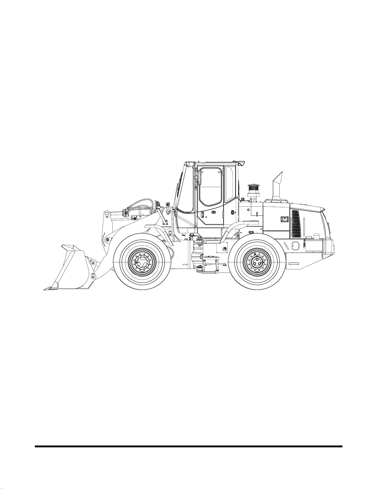
FG001781
Figure 2

K1024537E
I-V
Presentation
A machine or device which meets the requirements must be
CE marked. Our machines have been tested particularly for
electromagnetic interference. The CE marking of the
machine and the declaration of conformity also cover the
EMC directive.
If other electronic equipment is fitted to this machine, the
equipment must be CE marked and tested on the machine
with regard to electromagnetic interference.
COMMUNICATION EQUIPMENT
INSTALLATION
Protection Against Electromagnetic
Interference
This machine has been tested in accordance with EU
directive 89/336/EEC governing electromagnetic interference.
It is therefore very important that all nonapproved electronic
accessories, such as communication equipment, must be
tested before installation and use, since they can cause
interference to the electronic systems of the machine.
IMPORTANT
All installation of optional communication equipment must
be carried out by trained professionals and in accordance
with the DOOSAN CE instructions applicable to the
machine.

K1024537EPresentation
I-VI
PRODUCT PLATES
With the aid of the product plates, shown below, it is
possible to identify the machine and its components. The
Product Identification Number, PIN, indicates the model
designation, engine code and serial number of the machine.
The Component Identification Number, CIN, indicates the
serial number of the component. Make a note of the
identification numbers.
When ordering spare parts, and in all telephone enquiries or
correspondence the PIN and CIN must always be quoted.
6
8
1, 2
435
7
FG008048
Figure 1
Reference
Number Description
1 Primary Marking The machine PIN (stamped into right side).
2 Product Plate The manufacturer's name and address, machine PIN.
3Additional Plate
for Product Plate
Machine weight, engine output year of manufacture, year of delivery
and position of CE mark (EU/EEA countries only).
4 Cabin
The manufacturer's name and address, product number, machine
model designation, max. machine weight, cabin serial number, ROPS/
FOPS number and ROPS/FOPS certificate number.
5 Engine The engine type designation and number.
6 Front Axle The manufacturer's name and address and front drive axle CIN.
7 Transmission The manufacturer's name and address and transmission CIN.
8 Rear Axle The manufacturer's name and address and rear drive axle CIN.

OP000506
1-1
Safety
OP000506
1Safety
TO THE OPERATOR OF A
WHEEL LOADER
Please respect the importance of taking responsibility for
your own safety, and that of other people who may be
affected by your actions.
The safety information on the following pages is organized
into the following sections:
1. “General Safety Essentials” on page 1-4
2. “Location of Safety Labels” on page 1-4
3. “Unauthorized Modifications” on page 1-13
4. “General Hazard Information” on page 1-13
5. “Before Starting Engine” on page 1-22
6. “Machine Operation” on page 1-26
7. “Maintenance” on page 1-34
8. “Battery” on page 1-44
9. “Towing” on page 1-46
10. “Shipping and Transportation” on page 1-47
DANGER!
Improper use of wheel loader could cause serious injury
or death. Before operating wheel loader, or performing
maintenance, operator or technician must read and
understand entire Operation and Maintenance Manual.
Any operation, maintenance, traveling or shipping
methods that do not follow safety guidelines printed in
this Manual could cause serious injury or death.

OP000506Safety
1-2
Learn Signal Words Used With Safety
Alert Symbol
The words "CAUTION," "WARNING," and "DANGER" used
throughout this manual and on decals on the machine
indicate degree of risk of hazards or unsafe practices. All
three degrees of risk indicate that safety is involved.
Observe precautions indicated whenever you see the Safety
Alert "Triangle," no matter which signal word appears next to
the "Exclamation Point" symbol.
SAFETY ALERT SYMBOL
Be Prepared – Get to Know All Operating and Safety
Instructions.
This is the Safety Alert Symbol. Wherever it appears –
in this manual or on safety signs on the machine – you
must be alert to potential for personal injury or
accidents. Always observe safety precautions and follow
recommended procedures.
CAUTION!
This word is used on safety messages and safety labels
and indicates potential of a hazardous situation that, if
not avoided, could result in minor or moderate injury. It
may also be used to alert against a generally unsafe
practice.
WARNING!
This word is used on safety messages and safety labels
and indicates potential of a hazardous situation that, if
not avoided, could result in serious injury or death. It
may also be used to alert against a highly unsafe
practice.
DANGER!
This word is used on safety messages and safety labels
and indicates an imminent hazard of a situation that, if
not avoided, is very likely to cause death or extremely
serious injury. It may also be used to alert against
equipment that may explode or detonate if handled or
treated carelessly.

OP000506
1-3
Safety
Safety precautions are described in SAFETY from page 1-4
on.
DOOSAN cannot predict every circumstance that might
involve a potential hazard in operation and maintenance.
Therefore the safety messages in this manual and on the
machine may not include all possible safety precautions. If
any procedures or actions not specifically recommended or
allowed in this manual are used, you must be sure that you
and others can do such procedures and actions safely and
without damaging the machine. If you are unsure about the
safety of some procedures, contact a DOOSAN distributor.

OP000506Safety
1-4
GENERAL SAFETY
ESSENTIALS
Accessory Applications
The wheel loader has been designed primarily for moving
earth with a bucket. For use as a grapple or for other object
handling, contact DOOSAN. Lifting-work applications are
permitted in approved lift configuration, to rated capacity
only, with no side-loading (unless prohibited by local
regulation). Do not use machine for activities for which it
was not intended. Do not use bucket for lifting work, unless
lift slings are used in approved configuration.
LOCATION OF SAFETY
LABELS
The operator should know and pay attention to the
information and warning plates/decals which are positioned
on the machine.
There are several specific warning signs on this machine.
The exact location of hazards and the description of the
hazards are reviewed in this section.
Please become familiarized with all warning signs.
Make sure that all of the warning signs are legible. Clean
the warning signs or replace the warning signs if you cannot
read the words. Replace the illustrations if the illustrations
are not visible. When you clean the warning signs, use a
cloth, water and soap. Do not use solvent, gasoline, or other
harsh chemicals to clean the safety signs. Solvents,
gasoline, or other harsh chemicals could loosen the
adhesive that secures the warning sign. Loose adhesive will
allow the warning sign to fall off.
Replace any safety sign that is damaged, or missing. If a
safety sign is attached to a part that is replaced, install a
safety sign on the replacement part.

OP000506
1-5
Safety
1310
12
64115 9
83 7 10
946
2
FG008049
Figure 1

OP000506Safety
1-6
1. Warnings for Operation, Inspection
and Maintenance (4190-2545A,
190-00092)
2. Warnings for Cooling Fan
(2190-3315, 190-00557)
CAUTION!
•Read manual and labels before
operation and maintenance. Follow
instructions and warnings in manual
and on labels on machine.
• Sound horn to alert people nearby
before operating, and make sure all
persons are clear of area.
• Always make sure when leaving
operator's seat to:
• Lower bucket or other working
tools to ground.
• "LOCK" transmission selector in
"NEUTRAL."
• Set park brake.
• Turn starter switch "OFF." Remove key from switch.
• If hydraulic components and units are ABNORMAL, consult nearest DOOSAN dealer or
authorized service shop. Do not attempt to make an overhaul.
ACO1360L
WARNING!
Keep your hands away from the fan during
operation. Entanglement in the fan can cause
serious injury.
AMO0390L

OP000506
1-7
Safety
3. Warnings When Opening Engine
Hood (190-00095)
4. Warnings for Using Wheel Block
(4190-2547A, 190-00207)
WARNING!
Before opening hood, shut down engine.
ACO1420L
WARNING!
Block wheels to prevent machine movement
before disengaging park brake.
AMO0400L

OP000506Safety
1-8
5. Warnings for Handling Accumulator
(190-00703, 190-00099)
Accumulator
Wheel loader pilot control system is equipped with an
accumulator. Accumulator will store a pressure charge that
may enable hydraulic controls to be activated for a brief
period of time after engine has been shut down. Activation
of any controls may enable selected function to operate
under force of gravity.
When shutting machine down, lower front attachment to
ground. After engine has been shut down, turn key to "ON"
position and move joystick controls to release pressure in
accumulator. Remove key.
WARNING!
Explosion hazard:
• Keep away from flame.
• Do not weld or drill.
ACO1480L
CAUTION!
Any raised attachment will lower to ground if
accumulator holds a charge.
IMPORTANT
Refer to Shop Manual for service procedures. Do not
release any pilot lines until pressure within accumulator
has been released.
Other manuals for DL200
1
This manual suits for next models
1
Table of contents
Other Doosan Forklift manuals

Doosan
Doosan D40S-5 Manual

Doosan
Doosan BSL14S-7 User manual

Doosan
Doosan D110S-5 with OCDB Quick start guide

Doosan
Doosan D20S-9 Manual

Doosan
Doosan D20G Quick start guide

Doosan
Doosan D20G User manual

Doosan
Doosan D35C-5 FDA04 Manual

Doosan
Doosan D50S-5 Manual

Doosan
Doosan D60S-7 Manual

Doosan
Doosan DL160 User manual