Eoslift S15J User manual

BEFORE YOU BEGIN
Welcome to use our electric stacker. Your stacker is made of high quality steel and SPED mast and was
designed to give a durable, reliable and easy to use product. For your safety and correct operation, please
carefully read this instruction book and warnings on the stacker before using it.This Operation Instruction of
the stacker is edited for you to completely acquire and master the safety operation of the stacker.
All of the information reported herein is based on data available at the moment of printing. We reserve the
right to modify our own products at any moment without notice and incurring in any sanction. So, it is
suggested to always verify possible updates.
Operating Instructions
S15J
Semi-Electric Stacker
S15J
Eoslift Automation Technology Corp.
No.99, Yanjia Road, Yuantong Town, Haiyan, Zhejiang
6

1 Technical Specifications
2 Installation & Adjustment
3 Safety Guidance
4 Maintenance
5 Battery Power System
6 Battery Charging
7 Control Panel
8 Transportation, Loading, Commission & Storage
9 Trouble Shooting
10 Electric Wires Diagram
11 Hydraulic Flow Diagram
12 Parts List
1.1 Technical Specifications
KJ(Door frame)
1
Page 1
Page 3
Page 4
Page 4
Page 5
Page 5
Page 5
Page 6
Page 7
Page 8
Page 9
Page 10
CONTENTS
Model
Manufacture
Load Capacity
Inner Width of Legs
Outer Width of Legs
Min.Fork Height
Lift Height
Min.Mast Height
Fork Length
Fork Width
Fork Thickness
Fork Ajustable
Load wheels
Steer wheels
Overall Length
Turning Radius
Battery
Lifting Motor
Charger Output
lb
B1(in)
B2(in)
H1(in)
H(in)
H2(in)
L(in)
W(in)
T(in)
B3(in)
in
in
L1(in)
R(in)
V/AH
V/Kw
V/A
S15J
EOSLIFT
3300
33-49
41-57
1.4
118
80
42
3.9
1.4
8.3-33
φ
φ7.1x2
70
57
12V/160AH
12V/1.6Kw
12V/20A
2.8×2.8

23
1.2 Residual Capacity at different load centre with Lift height 118in.
2. Installation & Adjustment
2.1 Adjust the screws on the mast guard to removing and re-attaching it. The screws are always remaining
on the guard.
2.2 Use of the removable load backrest extension: during operation of the truck, if lift height exceeds 1.8 m,
it is suggested that an extension backrest should be added for the lifting part. The manufacturing and
installation of backrest should be completed by professional personnel specialized in industrial vehicle.
With regard to detailed requirements, you should contact the manufacturer.
KJ(Door frame)
3000
2500
2000
1500
1000
500
18
Load Centre(in.)
24 30 36 42 48
Capacity
(LB)
4000
3500
Raisde to 118 in.
C
Capacity Chart
45
3. Safety Guidance
3.1 Operator should read all warning signs and instructions here and on the stacker before using it.
3.2 Do not operate a stacker unless you are familiar with it and have been trained or authorized to do so.
3.3 Do not operate a stacker unless you have checked its condition. Give special attention to the chain, the
wheels, the handle, the guide frame, the pilot wheel, the mast, battery, etc.
3.4 Do not use on a slopping ground or on a barbaric or explosive danger environment.
3.5 Do not take up any people on the forks.
3.6 When forks lifting, forbid anyone to stand under the forks or pass through the forks.
3.7 The operator had better take on safety shoes and gloves for labor protecting against crushing and
shearing hazards. Keep feet out from underneath load.
3.8 Do not move the stacker when the goods are lifted to the height more than 300mm.
3.9 When the goods have been transported or lifted, all people should be away from the forks for 600mm.
3.10 The weight of goods should be distributed on the two forks, do not use only one fork. The center of
gravity of goods should be in the center of two forks.
3.11 Do not load over maximum capacity according to the capacity diagram. Heavy load should not be
allowed to remain on the forks for a long time after operation is over.
3.12 Before using or charging it, check cell liquid, if not enough, full it with distilled water.
3.13 Charging should be in dry and ventilated location, and far away from the fire.
3.14 Keeping the forks in the lowest position if not using.
3.15 Do not use the truck when traveling on lorries.
3.16 Do not use the truck in a potentially explosive atmosphere.
3.17 Do not use the truck as a vehicle jack.
3.18 Do not use under wind forces.
3.19 Do not use the truck on places insufficiently illuminated.
3.20 Do not use the truck with guarding removed.
3.21 Stackers should be parked on a smooth place, keep power off, lower the forks to the min. height, and
press on the brake. Stackers should not be parked in the unsafe area such as busy streets, intersections,
narrow roads, blind curves, slopes, soft ground, place around the
inflammable, fire fighting access.
3.22 At other special condition or place, the operator should be carefully to operate the stacker.
3.23 Unauthorized truck modification is not permitted. No modifications or alterations to a powered
industrial truck, which may affect, for example, capacity, stability or safety requirements of the truck,
shall be made without the prior written approval of the original truck manufacturer, its authorized
representative, or a successor thereof. This includes changes affecting, for example braking, steering,
visibility and the addition of removable attachments. When the manufacturer or its successor approve a
modification or alteration, they shall also make and approve appropriate changes to capacity plate,
decals, tags and operation and maintenance handbooks. Only in the event that the truck manufacturer is
no longer in business and there is no successor in the interest to the business, the user may arrange for
a modification or alteration to a powered industrial truck, provided, however, that the user shall:
a) Arrange for the modification or alteration to be designed, tested and implemented by an engineer(s)
expert in industrial trucks and their safety.
b) Maintain a permanent record of the design, test(s) and implementation of the modification or alteration.
c) Approve and make appropriate changes to the capacity plate(s), decals, tags and instruction handbook.
d) Affix a permanent and readily visible label to the truck stating the manner in which the truck has been
modified or altered together with the date of the modification or alteration, and the name and address of
the organization that accomplished the tasks.
4.1 Hydraulic oil
Please check the oil level every six months. The oil can be hydraulic oil: ISO VG32, its viscosity should
be 32cSt at 40℃, total volume is about 4.0lt. use temperature -20oC~50 oC
Replace the hydraulic oil (every 12 months).
4.2 Daily check and maintenance
It is necessary to check the stacker daily. Special attention should be paid to the wheels, the axles, as
thread, rags, etc., it may block the wheels, the fork and the mast, the chain, the battery should be
checked, too. The forks should be unloaded and lowered in the lowest position when the job is over.
4.3 Lubrication
Use motor oil or grease to lubricate all movable parts.
4.4 Maintenance of battery: Keep all the screw caps on each cell battery dry and clean. Each connecting
terminal and cable terminal should be tightened and painted with clean grease. The exposed connecting
terminal and connecting rod of battery should be covered with anti-slip insulated cover.
4.5 Recharge the battery fully and carry out usual battery maintenance. Charge the battery every third
month and check the fluid level.
4.6 Change the wheels
Put the unladen stacker on a smooth place, keep power off, lower the forks to the min. height. Keep the
wheels off the ground, take off the elastic retaining ring on one side of the wheel axle, take out the
wheel, put in the new wheel, and put back the elastic retaining ring.
4. Maintenance
5. Battery Power System
5.1 12V/120AH lead-acid storage battery is used in this series stacker.
5.2 The storage battery should be put in the special anti-spilling case which should be fixed with bolts.
5.3 The storage battery cannot be overturned during the process of installing and moving in case the acid
liquor spills out.
5.4 Keep power off when the stacker is not in use.
5.5 Please use the assorted charger or charger with same specifications, and follow Article 6 to charge the
battery.
6. Battery Charging
6.1 Charge storage battery when its voltage is less than 10 Volt.
6.2 Please check the battery liquid before charging, if it is not enough, add some distilled water.
6.3 The charging environment should be ventilated and far away from the fire.
6.4 If the stacker not use for long time, charge it for not less than two hours every week.
6.5 The voltage on the indicator should not be over 15 Volt when charging.
6.6 Do not use the stacker when charging.
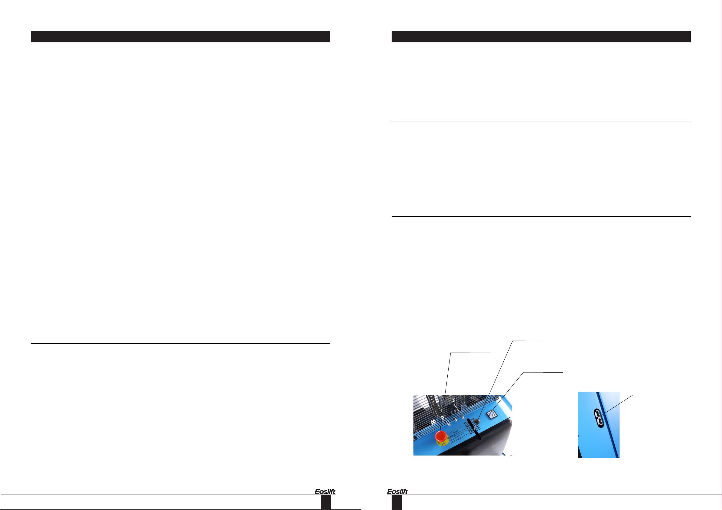
7. Control Panel
7.1 Emergency Stop
When you press down this switch, it will switch off the power, and then you turn it clockwise, it will switch on
the power.
7.2 Battery indicator
It indicates the voltage of battery. When its voltage is less than 10 Volt, you should not use this stacker, you
must charge it.
7.3 Control stick
This stick controls the forks to lower or lift. Push forward to make the motor start. Push backward and down
to make the pressure released and the oil return to tank.
7.4 Charger socket
Charger socket
battery charge
indicator
emergency stop
&on/off switch
raise /lower lever
67
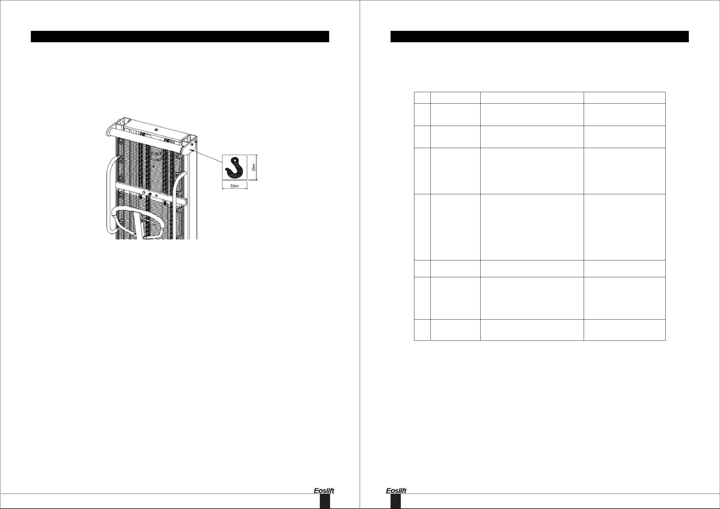
8. Transportation, Loading, Commissioning And Storage
If the truck has to be transported for a long distance, it should be packed in the container in order to avoid
collision during transportation.
8.1 The truck is packed properly in a container and transported by hoisting apparatus. Lifting points are on
both sides of the stacker, which are identified as the below picture.
8.2 Before loading, the operator shall make sure the truck weight on the nameplate to choose the suitable
hoisting equipment. When the truck is unloaded, the operator shall look out for safety around to ensure
slow landing of the truck.
8.3 On completion of commissioning, the truck shall be submitted to and verified according to the following
function test: steering, traveling, braking, load handling controls and combined functions with rated
capacity.
8.4 When a truck is inoperative, the load (if applicable) shall be removed with a proper tool and measure, the
truck shall be transported out of the working zone with a proper way.
8.5 When the truck will be shutdown and in storage for a long time, the storage environment shall be kept dry
and clean, fork shall be lowered to its lowest position.
9. Troubles Shooting
NO. Trouble Clause Fixing Methods
1
The forks can not
be up the max.
height.
-The hydraulic oil is not enough. -Pour in the oil.
2
The forks can not
be lifted up.(Motor is
rotary)
-Without hydraulic oil.
-The oil has impurities.
-Fill in the oil.
-Change the oil.
3 The motor cannot
run.
-The urgent switch is pressed down, cut
off the power.
-The voltage is too lower.
-The connectors of electrical wire is
loose.
-The contactor of DC motor is bad.
-Turn it clockwise, switch on the
power
-Charge it.
-Turn it firm.
-Replace with new one.
4 The forks cannot
be descended.
-The piston rod or mast is deformed
resulting from partial loading slanting to
one side or over-loading.
-The fork was kept in the high position for
long time with piston rod bared to arise in
rusting and jamming of the rod.
-The release valve of pump is not
opened.
- Replace with new one.
-Keeping the fork in the lowest
position if not using, and pay
more attention to lubricate the
rod.
-Check it, if damaged, replace
with new one.
5 Leaks -Sealing parts worn or damaged.
-Some part cracked or worn into small.
-Replace with the new one.
-Replace with the new one.
6
The fork descends
without the release
valve worked.
-The impurities in the oi l cause
the release valve to be unable to close
tight.
-Sealing parts worn or damaged.
-The release valve is damaged.
-Replace with new oil.
-Replace with the new one.
-Replace with the new one.
7 Battery cannot be
Charged
-Battery is bad.
-The charging plug is loose.
- Replace with the new one.
- Turn it firm.
89
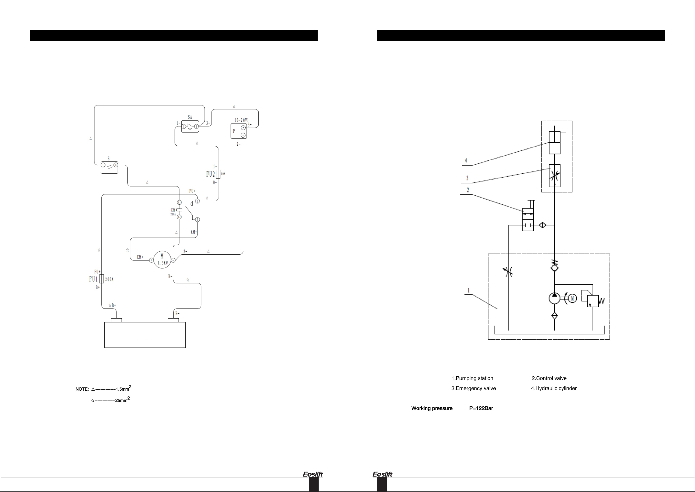
11. Hydraulic Flow Diagram10. Electric Wires Diagram
Circuit Diagram
GB 12V 160AH
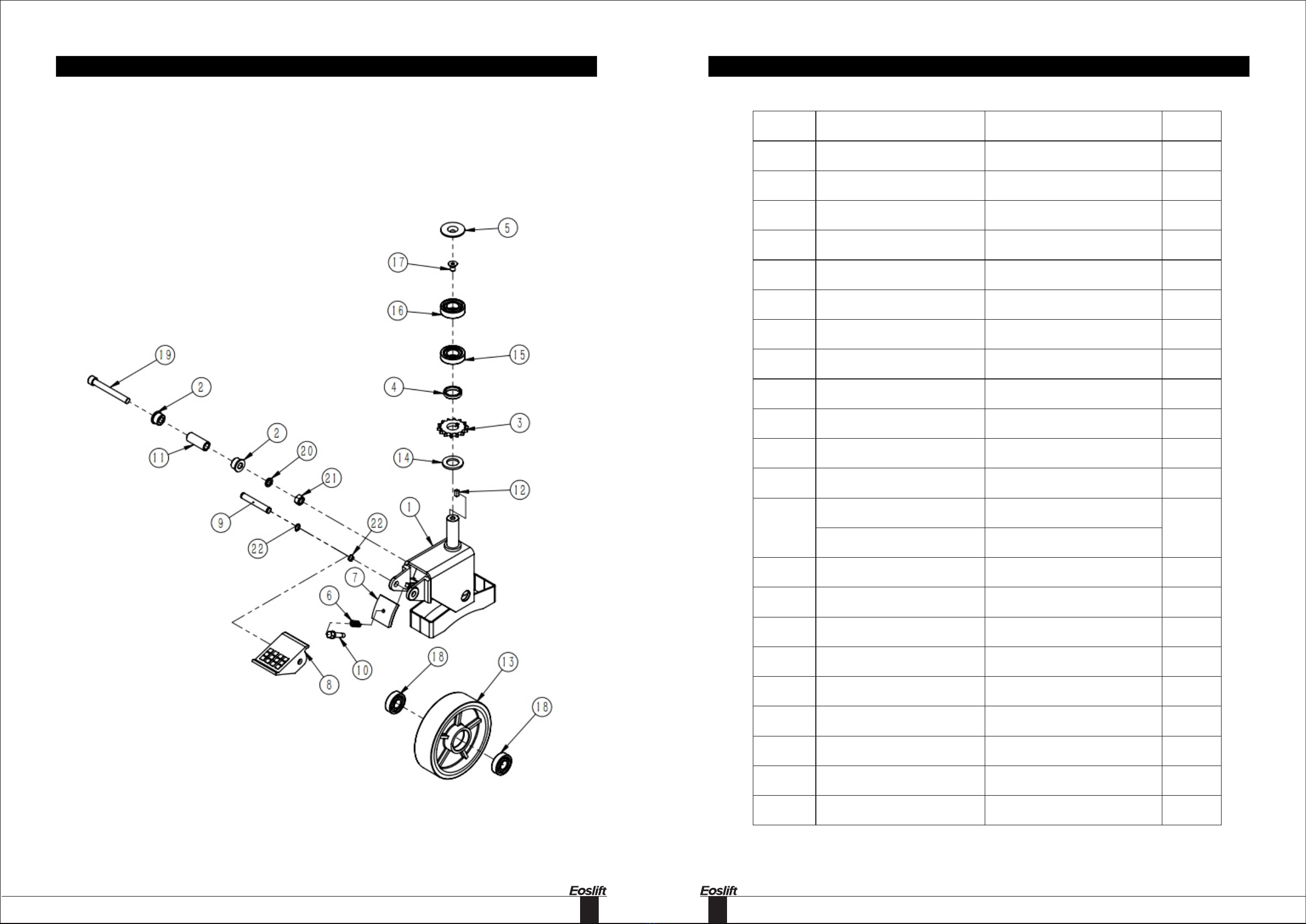
12 Parts List
Universal wheel with brake
1011
No. Stock Number Description Qty.
1
2
3
4
5
6
7
8
9
10
11
12
13
14
15
16
17
18
19
20
21
22
WC 02000237
WC02000234
WC02000243
WC02000244
WC02000245
WC02000240
WC02000238
WC02000241
WC02000242
WC02000239
WC02000235
WC02000236
WC02000226
WC02000285
WE05000010
WC02000225
WC02000224
WE03000013
WC02000022
WE03000018
WE05000006
WE04000011
WE 07000009
steering wheel frame with brake,black
steering axle sleeve 1
chain wheel
backing ring
wheel cap
pressure spring
brake plate,galvanized
brake pedal
brak pedal axis
axial view bolts
steering axle sleeve2
key
iron core PU wheelφ180×50,PU red,
iron coreblack
nylon wheelφ180×50(flower shape wheel)
GB95 Plain washer 24,galvanized
GB297,circular cone running pulley
bearing 30205
GB276,deep groove ball bearing6205,
two-side dusty cover
GB2673,Inner hex screw M10×16,
galvanized
GB276,deep groove ball bearing6204,
two-side dusty cover
GB70.1 Hex socket screw M10×100,
galvanized
GB93 Spring washer 12,galvanized
GB6170 Hex nut M12,galvanized
GB894.1 Circlip for Shaft 12,black
1
2
1
1
1
1
1
1
1
1
1
1
1
1
1
1
1
2
1
1
1
2
Universal wheel with brake

1213
No. Stock Number Description Qty.
1
2
3
4
5
6
7
8
9
10
11
12
13
WC 02000246
WC02000022
WC02000234
WC02000226
WC02000285
WC02000235
WE03000018
WE05000006
WE04000011
WC02000245
WE05000010
WC02000225
WC02000224
WE 03000013
guide pulley seat,black
GB276,deep groove ball bearing6204,
two-side dusty cover
steering axle sleeve 1
iron core PU wheelφ180×50,PU red,
iron coreblack
nylon wheelφ180×50(flower shape wheel)
steering axle sleeve2
GB70.1 Hex socket screw M10×100,
galvanized
GB93 Spring washer 12,galvanized
GB6170 Hex nut M12,galvanized
wheel cap
GB95 Plain washer 24,galvanized
GB297,circular cone running pulley
bearing 30205
GB276,deep groove ball bearing6205,
two-side dusty cover
GB2673,Inner hex screw M10×16,
galvanized
1
2
1
1
1
1
1
1
1
1
1
1
2
Universal wheel without brake Universal wheel without brake

14 15
No. Stock Number Description Qty.
1
2
3
4
5
6
7
8
9
10
11
12
13
WC 02000252
WC02000248
WE07000008
WC02000249
WC02000247
WC02000242
WC02000251
WC02000250
WE07000009
WC02000224
WC02000244
WC02000243
WC02000236
WE05000010
WE 04000016
handle assembly
gas spring
GB894.1 Circlip for Shaft 10,black
axle 2,galvanized
handle seat,black
brak pedal axis
axle 3,galvanized
axle sleeve,galvanized
GB894.1 Circlip for Shaft 12,black
GB276,deep groove ball bearing6205,
two-side dusty cover
backing ring
chain wheel
key
GB95 Plain washer 24,galvanized
GB889.1 Hex lock nut M18,galvanized
1
1
1
2
2
2
1
1
1
1
14
1
15
1
4
1
1
Handle assembly
Handle assembly
16 17
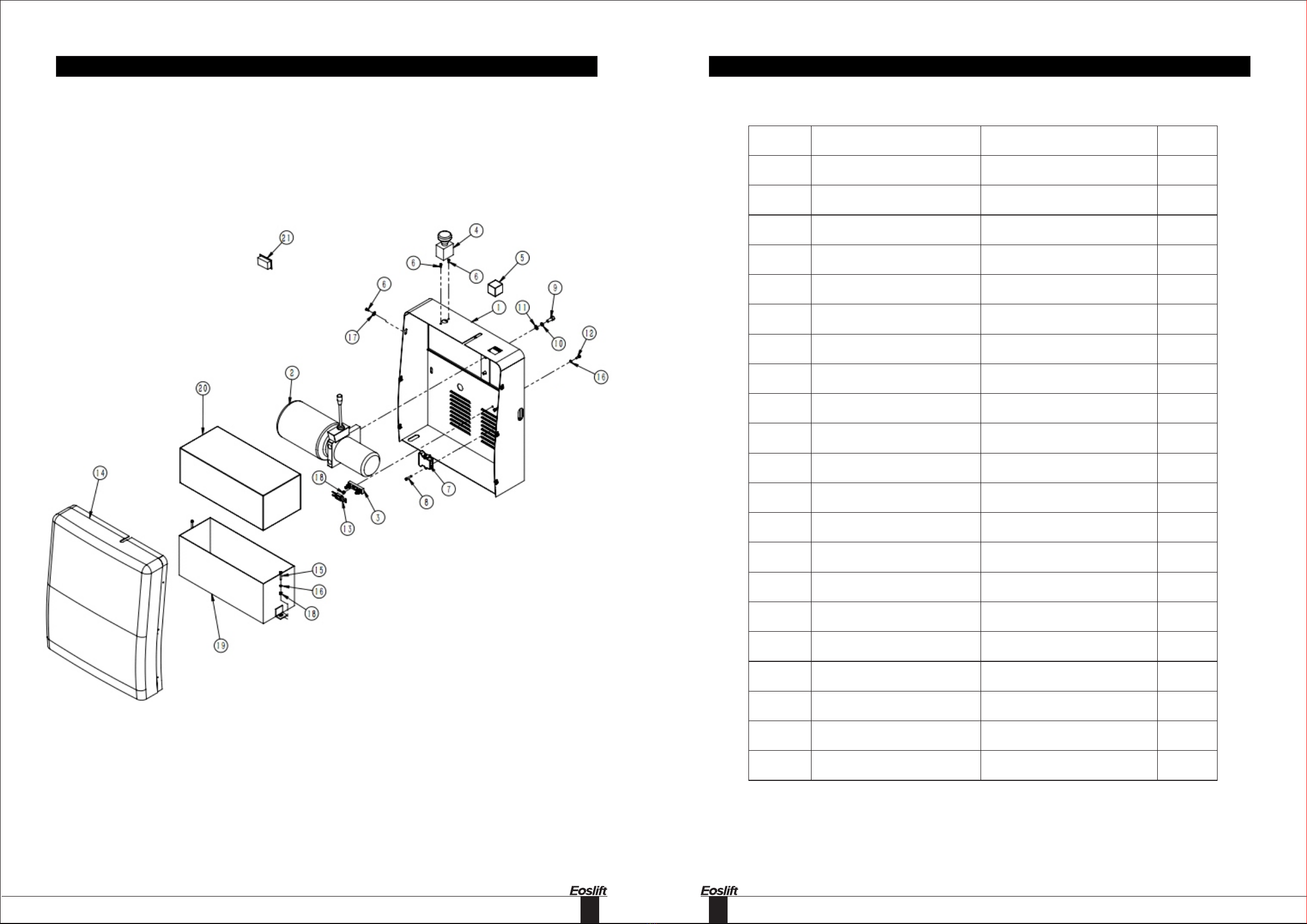
No. Stock Number Description Qty.
1
2
3
4
5
6
7
8
9
10
11
12
13
WC 02000253
WC02000269
WC04000022
WC04000020
WC04000013
WE03000006
WC01000014
WE03000015
WE03000004
WE05000002
WE05000009
WE03000001
WC04000011
WC02000254
WE01000003
WE05000003
WE05000007
WE04000017
WC02000255
WC02000268
WC 01000044
Electrical Cabinet,5012
hydraulic pumpDC12160 12V 160KW
fuse connect seat RQD-1 220V 800A
The abrupt stop switch ZJK250A
nstrument JY-99 20V
GB818 Screw M5×12,galvanized
charger socket line
GB70.1 Hex socket screw M6×25,
galvanized
GB70.1 Hex socket screw M10×25,
galvanized
GB93 Spring washer 10,galvanized
GB95 Plain washer 10,galvanized
GB70.1 Hex socket screw M6×16,
galvanized
CNL300 chip fuse
cover,black
GB5781 Hex bolt M6×35,galvanized
GB95 Plain washer 6,galvanized
GB96.1 Washer 6,galvanized
GB889.1 Hex lock nut M6,galvanized
battery box(120),black
Uniform dosing batteryN120Ah
Charger CZC7-20A/12V
(American standard)
1
1
1
1
1
8
1
2
2
2
2
2
1
1
2
4
6
4
1
1
1
14
15
16
17
18
19
20
21
Motor Box Motor Box

18 19
Parts List for SPN1016G
No. Stock Number Description Qty.
1
2
3
4
5
6
7
8
9
10
11
12
13
WC 01000017
WC02000303
WC02000275
WC02000272
WC02000304
WC02000274
WC02000273
WC02000279
WE05000011
WE04000018
WC02000278
WC02000276
WC02000280
WC 02000277
Black cylinder assembly
oil cylinderseaming part,black
guide sleeve
hood,galvanized
piston rod
gasket,galvanized
piston
GB3452.1,O-ringφ26.2×2.4
GB93 Spring washer 24,galvanized
GB6171 Hex nut M24×1.5,galvanized
ZS50 guild ring 50×55×14.8
DH45 dusty ring 45×53×6.5
UHS45 seal ring45×56×7
GB3452.1,O-ringφ50.8×3.1
1
1
1
1
1
1
1
2
1
1
1
1
1
1
14
Cylinder assembly
Cylinder assembly

20 21
No. Stock Number Description Qty.
1
2
3
4
5
WC 02000219
WC02000263
WC02000262
WC02000265
WC 02000220
chain
screw(right)
screw sleeve
screw(left)
single row running pulley chain CL
contact 08A-1
2
2
2
2
4
No. Stock Number Description Qty.
1
2
3
4
5
WC 02000325
WJ11900012
WJ11900006
WJ11900005
WJ11900004
WJ11900003
WJ11900002
WJ11900001
WJ 11900015
Leaf chain
Leaf chain
LH1223 Long end joint
Spherical nut
GB6171,nut M14×1.5×12.8
GB91,Cotter pin 2×16
GB91,Cotter pin 2×32
GB91,Cotter pin 3.2×32
The chain pin shaft
2
2
2
2
6
7
2
8
9
2
4
2
2
Chain Plate link chain
22 23
No. Stock Number Description Qty.
1
2
3
4
5
WC 02000299
WE07000006
WC02000022
WE07000004
WC02000317
WE03000019
WE07000007
WC02000224
WE07000010
WC02000231
WC02000232
WD01000211
WE03000020
WE 03000017
inner mast,5012
GB893.1 Cieclip for hole 47,black
GB276,deep groove ball bearing6204,
two-side dusty cover
GB894.1 Circlip for Shaft 20,black
chain wheel(Leaf chain)
Gb77 Hexagon flat set screw M12×20,
galvanized
GB893.1 Cieclip for hole 52,black
GB276,deep groove ball bearing6205,
two-side dusty cover
GB894.1 Circlip for Shaft 25,black
steel wheel
steel wheel cap
down support pole
GB70.1 Hex socket screw M10×12,
galvanized
GB70.1 Hex socket screw M8×12,
galvanized
1
2
2
2
2
8
4
4
4
4
4
1
2
1
6
7
8
9
10
11
12
13
14
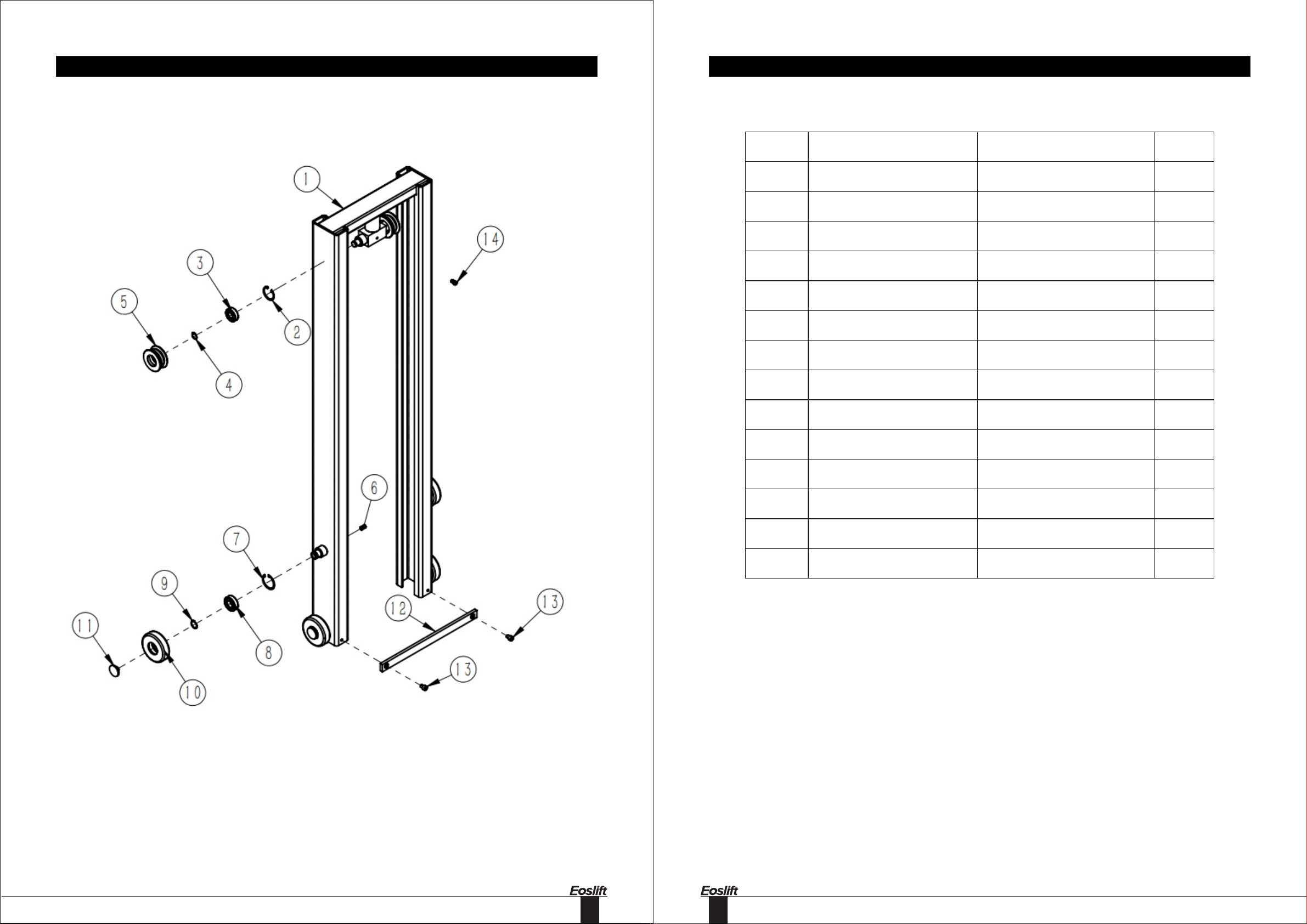
Mast assy - outer
Mast assy - outer

24 25
No. Stock Number Description Qty.
1
2
3
4
WC 02000266
WC02000301
WC02000267
WC02000223
WC 02000228
fuel injection pipe
oil return pipe
bolt
rectangular connector
GB982,sseal washer 18
5
1
1
2
2
4
No. Stock Number Description Qty.
1
2
3
WC 02000713
WC02000712
WC02000022
WE07000004
WC02000227
WC02000286
WC 02000259
The right fork leg welded,5012
The left fork leg welded,5012
deep groove ball bearing6204
Circlip for Shaft 20,black
iron corePU wheel φ70×70,PU red
nylon wheelφ70×70
steering wheel axle
4
1
4
4
2
2
5
Oil tube Front wheel assembly
26 27
No. Stock Number Description Qty.
1
2
3
4
5
6
7
8
9
10
11
12
13
14
15
16
17
18
19
20
21
22
23
24
25
26
WC 02000832
WE04000005
WE05000004
WE03000016
WC02000292
WC02000302
WE04000013
WE04000014
WE05000005
WE05000008
WE05000009
WE05000002
WE04000009
WE01000002
WC02000264
WE01000006
WE04000022
WC02000710
WC02000709
WE05000005
WC02000293
WC02000294
WC02000295
WE03000014
WE07000008
WC 02000020
outer mast,5012
GB6170 Hex nut M5,galvanized
GB95 Plain washer 5,galvanized
GB70.1 Hex socket screw M5×16,
galvanized
gauze pad,black
gauze pad,black
GB802 Cap Nut M10,galvanized
GB802 Cap Nut M8,galvanized
GB93 Spring washer 8,galvanized
GB95 Plain washer 8,galvanized
GB95 Plain washer 10,galvanized
GB93 Spring washer 10,galvanized
GB6170 Hex nut M10,galvanized
GB5781 Hex bolt M10×50,galvanized
locking ring
GB5783 Hex bolt M16×40,galvanized
GB6170 Hex nut M16,galvanized
Support shaft Ⅱ,galvanized
Support shaft I,galvanized
GB93 Spring washer 8,galvanized
top guild wheel
top guild plate,galvanized
pin roll
GB70.1 Hex socket screw M8×20,
galvanized
GB894.1 Circlip for Shaft 10,black
GB308,steel ball S18
1
8
8
8
1
1
1
2
2
2
1
1
1
1
1
8
8
2
2
2
2
2
2
4
2
1
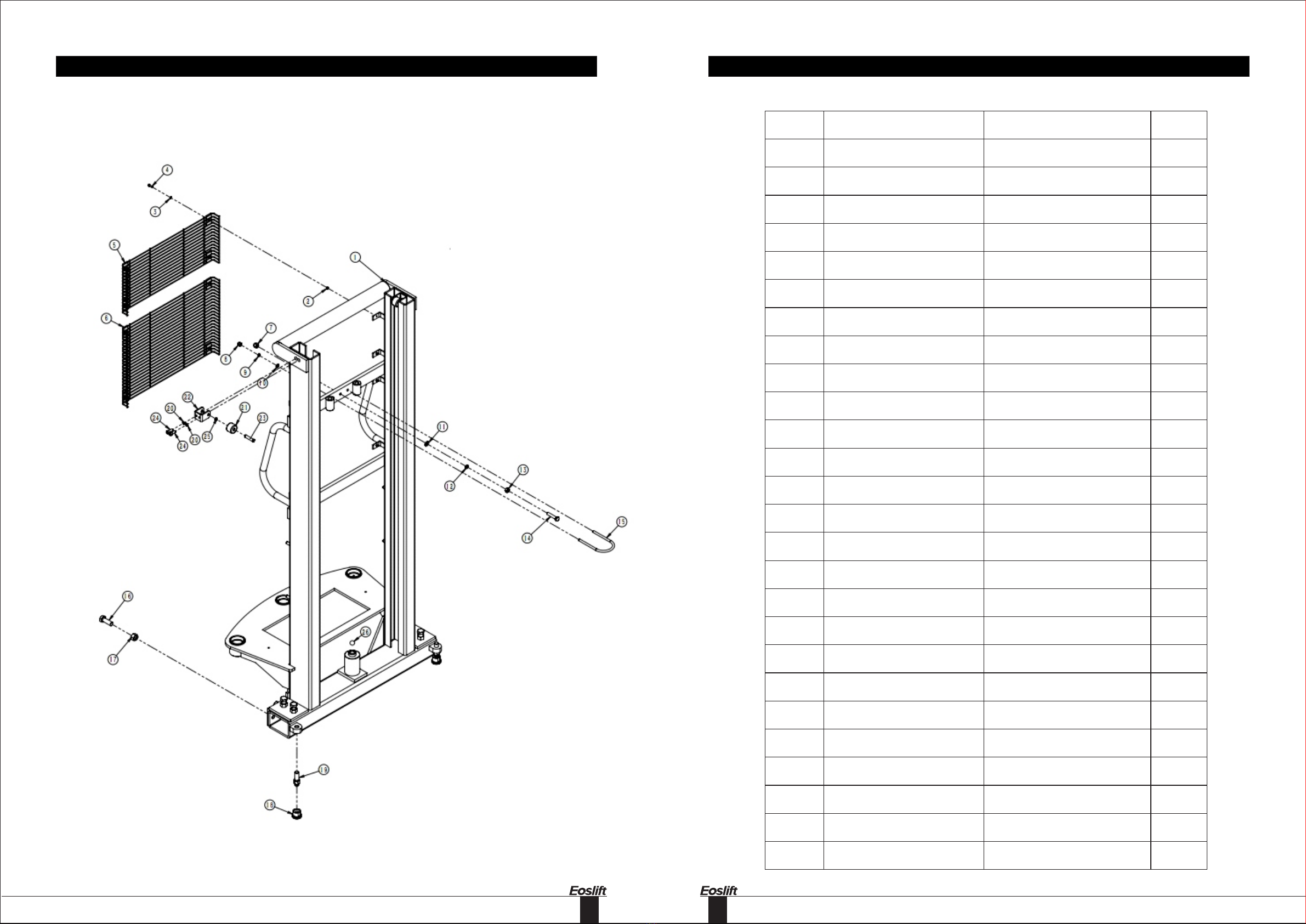
Mast assy - inner
Mast assy - inner

28
No. Stock Number Description Qty.
1
2
3
4
5
6
7
8
9
10
11
WC 02000323
WC02000283
WC02000284
WC02000711
WE07000011
WE03000019
WC02000232
WC02000231
WC02000224
WE07000007
WE 07000010
fork guide plate,black
axle (830),galvanized
adjustable bolt,galvanized
telescope-feed fork,black
GB894.1 Circlip for Shaft 32,black
Gb77 Hexagon flat set screw M12×20,
galvanized
steel wheel cap
steel wheel
GB276,deep groove ball bearing6205,
two-side dusty cover
GB893.1 Cieclip for hole 52,black
GB894.1 Circlip for Shaft 25,black
1
1
2
2
2
4
4
4
4
4
4
Forks
Table of contents
Other Eoslift Forklift manuals


