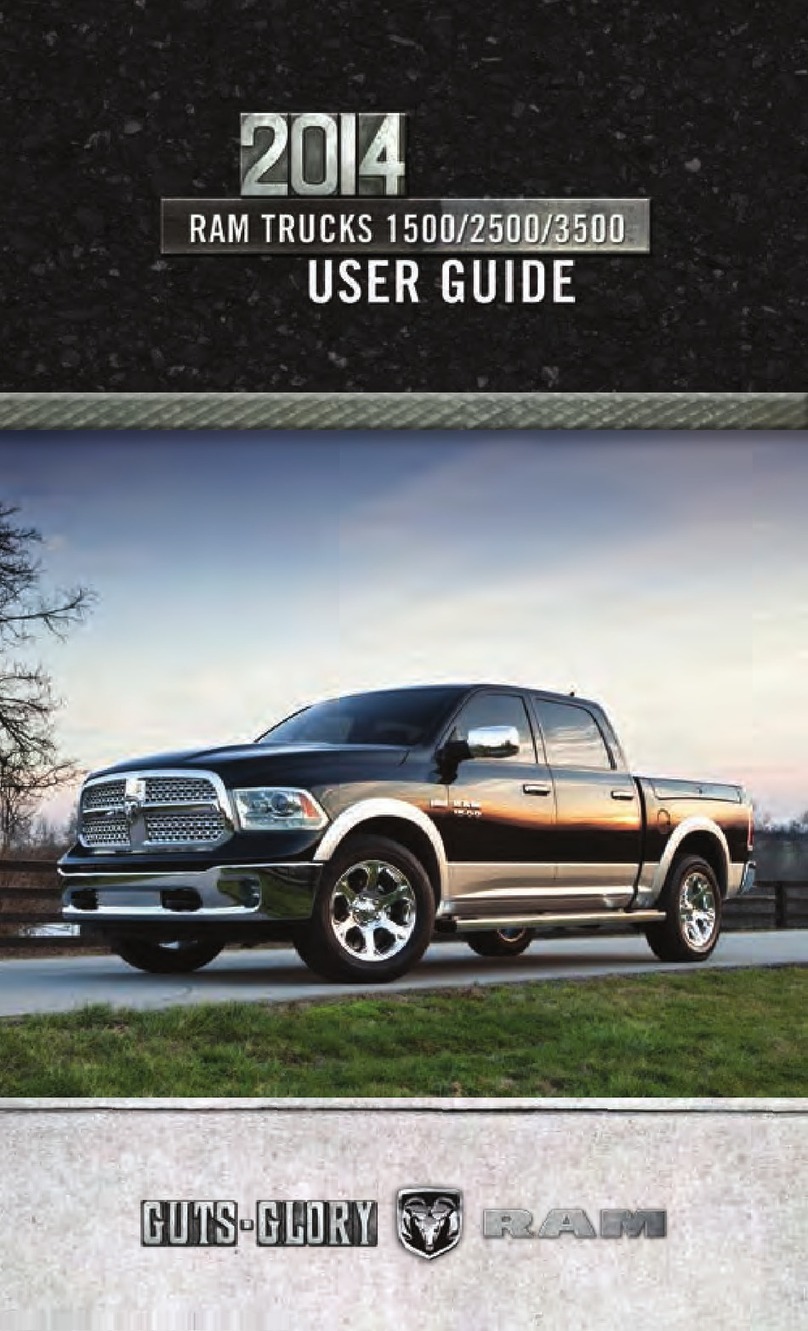
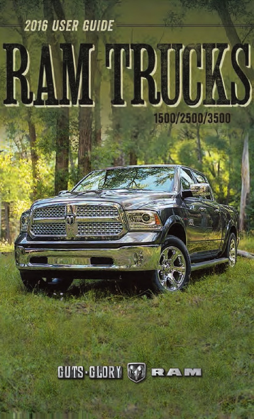
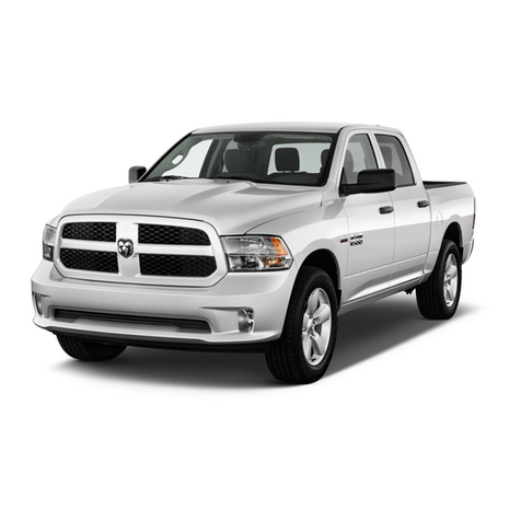
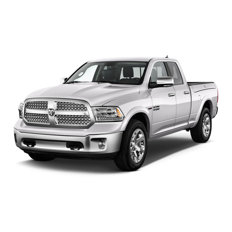
RAM 2014 TRUCK 1500 Configuration guide

1500/2500/3500
COMPRESSED NATURAL GAS
Chrysler Group LLC
OWNER’S MANUAL
SUPPLEMENT
2012
5600E2012A41E First Edition Printed in U.S.A.
RAM TRUCK

VEHICLES SOLD IN CANADA
With respect to any Vehicles Sold in Canada, the name
Chrysler Group LLC shall be deemed to be deleted and the
name Chrysler Canada Inc. used in substitution therefore.
DRIVING AND ALCOHOL
Drunken driving is one of the most frequent causes of acci-
dents.
Your driving ability can be seriously impaired with blood alcohol
levels far below the legal minimum. If you are drinking, don’t
drive. Ride with a designated non-drinking driver, call a cab, a
friend, or use public transportation.
WARNING!
Driving after drinking can lead to an accident. Your per-
ceptions are less sharp, your reflexes are slower, and your
judgment is impaired when you have been drinking.
Never drink and then drive.
This manual illustrates and describes the operation of features
and equipment that are either standard or optional on this
vehicle. This manual may also include a description of features
and equipment that are no longer available or were not ordered
on this vehicle. Please disregard any features and equipment
described in this manual that are not on this vehicle.
Chrysler Group LLC reserves the right to make changes in
design and specifications, and/or make additions to or im-
provements to its products without imposing any obligation
upon itself to install them on products previously manufac-
tured.
Copyright © 2011 Chrysler Group LLC

TABLE OF CONTENTS
SECTION PAGE
1
INTRODUCTION
............................................................3
2
THINGS TO KNOW BEFORE STARTING YOUR VEHICLE
..............................5
3
UNDERSTANDING YOUR INSTRUMENT PANEL
................................... 11
4
STARTING AND OPERATING
.................................................25
5
MAINTAINING YOUR VEHICLE
...............................................29
6
MAINTENANCE SCHEDULES
..................................................33
7
INDEX
....................................................................35
1
2
3
4
5
6
7


INTRODUCTION
CONTENTS
䡵Introduction ........................... 4
1

INTRODUCTION
This booklet is a supplement to the Ram Truck Gas 2500
Owner’s Manual. It contains information relative to the
Compressed Natural Gas equipment installed on this
vehicle by the manufacturer. You are urged to read this
publication and the Owner’s Manual carefully.
Following the instructions and recommendations pro-
vided herein will help assure safe and reliable operation
of your vehicle. After you have read the booklet it should
be stored in the vehicle for convenient reference and
remain with the vehicle when sold.
4 INTRODUCTION

THINGS TO KNOW BEFORE STARTING YOUR VEHICLE
CONTENTS
䡵General Information ..................... 6
䡵Safety Warnings ........................ 6
䡵Manual Shut Off Valve .................... 8
2

GENERAL INFORMATION
Your vehicle is designed to operate on gasoline or Com-
pressed Natural Gas (CNG). Compressed Natural Gas is
made up primarily of methane and is in a gaseous state
at all times.
The manufacturer’s built vehicles equipped with com-
pressed natural gas fueled engines are identified by the
character T in the eighth (engine) position of the Vehicle
Identification Number (V.I.N.)
SAFETY WARNINGS
Natural gas is safe and reliable, when used properly. For
safe operation of your vehicle, observe the following
precautions:
•
Your vehicle fuel system has a maximum capacity of
3,600 pounds per square inch gauge (24.8 MPa) com-
pensated to a temperature of 70° F (21° C). The vehicle
should only be filled from refueling equipment incor-
porating temperature compensation to 70° F (21° C).
Exceeding the fuel system capacity may result in fuel
system damage and possibly cause injury.
•
Do not attempt to force open or tamper with the fuel
fill receptacle. A sudden release of natural gas may
occur, possibly causing injury.
•
Natural gas contains an odorant additive and persis-
tent natural gas odor may indicate a leak. If a persis-
tent natural odor is detected, the cause should be
located and corrected immediately by a qualified
technician.
•
Do not park or service your vehicle near any source of
excessive heat or open flame. Never use a paint oven
to cure any paint repairs. The natural gas storage
containers on this vehicle are equipped with pressure
relief devices which vent at 230° F (110° C).
•
Do not paint or under coat any natural gas fuel system
components.
6 THINGS TO KNOW BEFORE STARTING YOUR VEHICLE

•
Unlike gasoline, a compressed natural gas fuel system
is under pressure even when the engine is not running.
To avoid risk of personal injury, any repair to the fuel
system should be performed by a qualified technician.
•
Natural gas vapors at atmospheric pressure are lighter
than air and will rise and disperse in open areas. In
enclosed areas, natural gas vapor may collect and form
a combustible mixture. If the vehicle is routinely
placed in an enclosed area, the area should be pro-
vided with adequate ventilation and/or a natural gas
detection system. For long term storage, the manual
shutoff valve and individual container valves should
be closed.
•
When a vehicle is involved in an accident which has or
may have caused damage to the natural gas fuel
system, the system must be inspected and pressure
tested by a qualified technician before returning the
vehicle to service.
•
Any fuel system component, including the containers,
that has been subjected to fire may not be returned to
service due to reduced pressure capability.
2
THINGS TO KNOW BEFORE STARTING YOUR VEHICLE 7

MANUAL SHUT OFF VALVE
The manual one-quarter turn shut off valve is located
inside the protective cover for the tanks. It’s location is
identified by a label on the top of the cover. This valve
isolates the fuel containers from the rest of the fuel
system.
Manual Shut Off Valve Access Door
1—ValveOff
8 THINGS TO KNOW BEFORE STARTING YOUR VEHICLE

1—ValveOn
2
THINGS TO KNOW BEFORE STARTING YOUR VEHICLE 9


UNDERSTANDING YOUR INSTRUMENT PANEL
CONTENTS
䡵Instrument Cluster ..................... 12 䡵Instrument Cluster Descriptions ............ 13
3

INSTRUMENT CLUSTER
12 UNDERSTANDING YOUR INSTRUMENT PANEL

INSTRUMENT CLUSTER DESCRIPTIONS
1. Tachometer
The tachometer indicates engine speed in Revolutions
Per Minute (RPM x 1000).
CAUTION!
Do not operate the engine with the tachometer
pointer at high RPM for extended periods. Engine
damage may occur.
2. Turn Signal Indicators
The arrow will flash with the exterior turn signal
when the turn signal lever is operated.
NOTE:
•
A continuous chime will sound if the vehicle is driven
more than 1 mile (1.6 km) with either turn signal on.
•
Check for an inoperative outside light bulb if either
indicator remains on and does not flash, or flashes at a
rapid rate.
3. Fuel Gauge
Shows level of fuel in tank when ignition switch is in the
ON/RUN position.
CAUTION!
Vehicle operation with an empty gasoline tank may
affect ability to start the engine and drivability,
especially when operating in cold weather.
4. CNG Gauge
Shows level of CNG (Compressed Natural Gas) in the
tanks when ignition switch is in the ON/RUN position.
NOTE: Depending on operating/weather conditions
the CNG gauge may fluctuate.
3
UNDERSTANDING YOUR INSTRUMENT PANEL 13

5. Speedometer
The speedometer shows the vehicle speed in miles per
hour and/or kilometers per hour (mph/km/h).
6. 4 LOW
This light alerts the driver that the vehicle is in
the four-wheel drive LOW mode. The front and
rear driveshafts are mechanically locked to-
gether forcing the front and rear wheels to
rotate at the same speed. Low range provides a greater
gear reduction ratio to provide increased torque at the
wheels.
For further information on four-wheel drive operation
and proper use, refer to “Four-Wheel Drive Operation —
If Equipped” in “Starting And Operating in your Own-
er’s Manual”.
7. 4WD Indicator
This light indicates the vehicle is in four-wheel
drive and 4LOCK. 4WD allows all four wheels
to receive torque from the engine simultane-
ously.
8. TOW/HAUL
The TOW HAUL button is located on the
center stack upper switch bank. This light will
illuminate when TOW HAUL mode is selected.
9. Vehicle Security Light — If Equipped
This light will flash at a fast rate for approxi-
mately 15 seconds, when the vehicle security
alarm is arming, and then will flash slowly
until the vehicle is disarmed.
14 UNDERSTANDING YOUR INSTRUMENT PANEL

10. Oil Pressure Gauge
The pointer should always indicate some oil pressure
when the engine is running. A continuous high or low
reading under normal driving conditions may indicate a
lubrication system malfunction. Immediate service
should be obtained from an authorized dealer.
11. Odometer/Trip Odometer Button/ECO (Fuel Saver
Indicator) Button — If Equipped
Press this button to toggle between the odometer display,
trip odometer display or the “ECO” display in the base
cluster. Holding the button in resets the trip odometer
reading when in trip mode.
If equipped with Electronic Vehicle Information Center
(EVIC) the “ECO” message will be displayed in the EVIC
display in the instrument cluster. Refer to ”Electronic
Vehicle Information Center (EVIC) — If Equipped” in
your Owner’s Manual for further information.
12. Odometer Display / Electronic Vehicle Information
Center (EVIC) Display Area — If Equipped
Odometer Display
The odometer display shows the total distance the ve-
hicle has been driven. U.S. Federal regulations require
that upon transfer of vehicle ownership, the seller certify
to the purchaser the correct mileage that the vehicle has
been driven. If your odometer needs to be repaired or
serviced, the repair technician should leave the odometer
reading the same as it was before the repair or service. If
s/he cannot do so, then the odometer must be set at zero,
and a sticker must be placed in the door jamb stating
what the mileage was before the repair or service. It is a
good idea for you to make a record of the odometer
reading before the repair/service, so that you can be sure
that it is properly reset, or that the door jamb sticker is
accurate if the odometer must be reset at zero.
3
UNDERSTANDING YOUR INSTRUMENT PANEL 15

The two trip odometers show individual trip mileage. To
switch from odometer to trip odometers, press and
release the TRIP ODOMETER button.
To reset a trip odometer, display the desired trip odom-
eter to be reset then push and hold the button for
approximately two seconds until the display resets.
Vehicle Odometer Messages
When the appropriate conditions exist, the following
messages will display in the odometer:
ECO ...................Fuel Saver Indicator Off
ECO-ON ................Fuel Saver Indicator On
noFUSE ..........................Fuse Fault
LoW tirE ....................TirePressure Low
CHANgE OIL............... OilChange Required
ESCOFF ............Electronic Stability Control Off
gASCAP ......................GasCapLoose
HOTOIL ...................Engine Oil Too Hot
LoCOOL................... LowEngine Coolant
NOTE: There is also an engine hour function. This
indicates the total number of hours the engine has been
running. To display the engine hours on the base cluster,
perform the following: Place the ignition in the ON/
RUN, but do not start the engine. With the odometer
value displayed, hold the TRIP button down for a period
of six seconds. The odometer will change to trip value
first, then it will display the engine hour value. The
engine hours will be displayed for a period of 30 seconds
until the ignition is turned OFF or the engine is started.
If equipped, some of the above warnings will be dis-
played in the Electronic Vehicle Information Center
(EVIC) in the instrument cluster. Refer to ”Electronic
Vehicle Information Center (EVIC) — If Equipped” in
your Owner’s Manual for further information.
ECO / ECO-ON (Fuel Saver Indicator) — If Equipped
The ECO-ON indicator will illuminate when you are
driving in a fuel efficient manner and can be used to
16 UNDERSTANDING YOUR INSTRUMENT PANEL

modify driving habits in order to increase fuel economy.
The ECO display will toggle between ECO and ECO-ON
depending on driving habits and vehicle usage. Press the
Odometer / Trip Odometer / ECO (Fuel Saver Indicator)
button to change the display from odometer to either of
the two trip odometer settings or the “ECO” display.
LoW tirE
When the appropriate condition exists, the odometer
display will toggle between Lo and tirE for three cycles.
noFUSE
If the vehicle diagnostic system determines that the
Ignition Off Draw (IOD) fuse is improperly installed, or
damaged, a “noFUSE” message will display in the odom-
eter display area. For further information on fuses and
fuse locations refer to “Fuses” in “Maintaining Your
Vehicle in your Owner’s Manual”.
CHANgE OIL
Your vehicle is equipped with an engine oil change
indicator system. The CHANgE OIL message will flash
in the instrument cluster odometer for approximately
12 seconds after a single chime has sounded to indicate
the next scheduled oil change interval. The engine oil
change indicator system is duty cycle-based, which
means the engine oil change interval may fluctuate
dependent upon your personal driving style.
Unless reset, this message will continue to display each
time you turn the ignition switch to the ON/RUN
position. To turn off the message temporarily, press and
release the Trip Odometer button on the instrument
cluster. To reset the oil change indicator system (after
performing the scheduled maintenance), refer to the
following procedure:
1. Turn the ignition switch to the ON/RUN position
(do not start the engine).
3
UNDERSTANDING YOUR INSTRUMENT PANEL 17

2. Fully depress the accelerator pedal slowly three
times within 10 seconds.
3. Turn the ignition switch to the OFF/LOCK position.
NOTE: If the indicator message illuminates when you
start the vehicle, the oil change indicator system did not
reset. If necessary, repeat this procedure.
13. Shift Lever Indicator
The Shift Lever Indicator is self-contained within the
instrument cluster. It displays the gear position of the
automatic transmission.
NOTE: In vehicles with 4.7L or 5.7L engines, the highest
available transmission gear is displayed in the lower
right corner of the Electronic Vehicle Information Center
(EVIC) whenever the Electronic Range Select (ERS) fea-
ture is active. Use the +/- selector on the shift lever to
activate ERS. Refer to “Automatic Transmission” in
“Starting And Operating” in your Owner’s Manual for
further information.
14. High Beam Indicator
This indicator shows that headlights are on high
beam. Push the multifunction lever forward to
switch the headlights to high beam, and pull toward
yourself (normal position) to return to low beam.
15. Temperature Gauge
The temperature gauge shows engine coolant tempera-
ture. Any reading within the normal range indicates that
the engine cooling system is operating satisfactorily.
The gauge pointer will likely indicate a higher tempera-
ture when driving in hot weather, up mountain grades,
or when towing a trailer. It should not be allowed to
exceed the upper limits of the normal operating range.
18 UNDERSTANDING YOUR INSTRUMENT PANEL
Other manuals for 2014 TRUCK 1500
3
This manual suits for next models
5
Table of contents
Other RAM Truck manuals

RAM
RAM 1500 CLASSIC 2022 User manual

RAM
RAM Chassis Cab 2014 User manual

RAM
RAM Truck 3500 2011 User manual

RAM
RAM RAM 3500 User manual

RAM
RAM Trucks 1500 User manual

RAM
RAM Trucks 1500 User manual

RAM
RAM 2014 TRUCK 1500 User manual

RAM
RAM 2500 2019 User manual

RAM
RAM 1500 2019 User manual

RAM
RAM 2014 TRUCK 1500 User manual
Popular Truck manuals by other brands

Toyota
Toyota 7FBMF 18 Repair manual

Scheppach
Scheppach DP4500 Translation of original instruction manual

Lift-Rite
Lift-Rite PST23 Owner's Manual, Operating Instructions Manual, and Replacement Parts Manual

Roughneck
Roughneck 25329 owner's manual

EKKO
EKKO EP18D Series manual

Linde
Linde 350 Series Service training