Eoslift M Series User manual
M Series
Operating Instructions
Hand
Pallet
Truck
Eoslift Automation Technology Corp.
No.99 Yanjia Road, Yuantong Town, Haiyan,
Zhejiang Province China 314317
Tel:+86 573 8622 9999
Fax: +86 573 8622 2900
info@eoslift.com
www.eoslift.com

Esteemed users:
For proper and safe operation of the products, before
using the products, be sure to read the operating
instructions carefully and retain them properly for
future reference.
The operator need to have proficient operation skills.
The operator has responsibility to carefully understand
the performance and safety rules of the pallet truck.
If you have any problemes during the application, please
contact Eoslift.
M Series Hand Pallet Trucks

Ⅰ.Technical parameters
01
Ⅱ. Safety rules 03
Ⅲ.Installation of handles 04
Ⅳ.Adjusting the finger grip handle
05
Table of contents
Ⅵ.Transportion, loading, test and storage
07
Ⅶ.Troubles shooting 08
Ⅷ.Parts list
Ⅴ.Maintenance
06
10
M Series Hand Pallet Trucks
01 02
M20/M25/M30/M20Q/M25Q/M30Q/M20Z/M25Z/M30Z
Rated capacity
Load center
Service weight
Wheel
Max. lift height
Min. fork height
Steer wheel
Load wheel
Single Load wheel
Fork width
Fork length
Overall length
Turning radius
M20L/M25L
Rated capacity
Load center
Service weight
Wheel
Max. lift height
Min. fork height
Steer wheel
Load wheel
Single Load wheel
Fork width
Fork length
Overall length
Turning radius
kg
mm
kg
mm
mm
mm
mm
mm
mm
mm
mm
mm
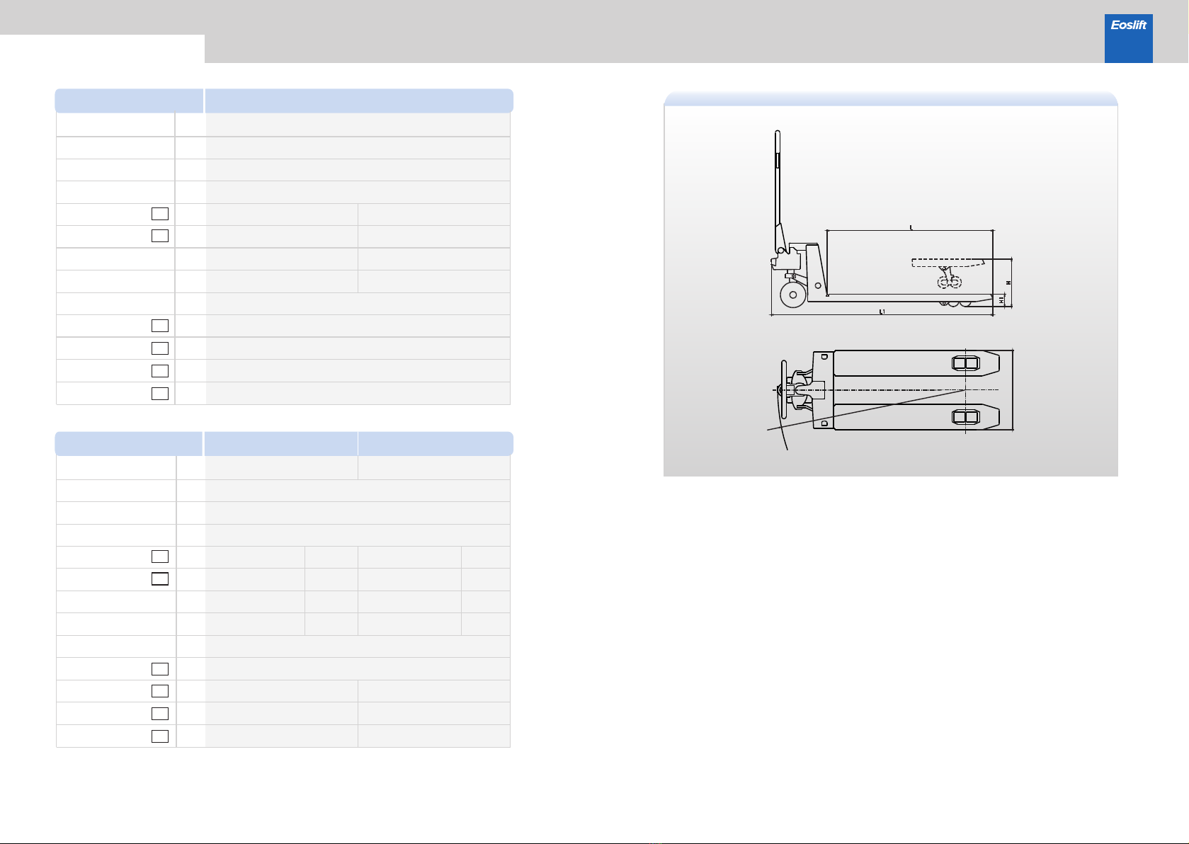
H
H1
B
L
L1
R
M30L
kg
mm
kg
mm
mm
mm
mm
mm
mm
mm
mm
mm
H
H1
B
L
L1
R
Technical parameters
Model
2000/2500/3000
600
72-79
PU/NYLON/RUBBER
200 190
85 75
Φ200x50/Φ180x50
Φ80x70
Φ74x93
540/685
1150/1220
1580/1650
1325/1395
Φ180x50
Φ74x70
Model
2000/2500
600
72-85
PU/NYLON/RUBBER
200 190
85 75
Φ200x50/Φ180x50
Φ80x70
Φ74x93
540/685
1500/1800/2000/2500
1930/2230/2430/2930
1675/1975/2175/2675
Φ180x50
Φ74x70
3000
200 190
85 75
Φ200x50/Φ180x50
Φ80x70
Φ180x50
Φ74x70
1500/1800/2000
1930/2230/2430
1675/1975/2175
B
R
M Series Hand Pallet Trucks

03 04
1.Make sure the chain on the handle
is in this position shown in the picture.
2.Push the handle shaft through the
holes, fix it with the spring pin.
3.Put the chain through the hole on the shaft. With the handle at 45º tilt.
4.Fix the chain in the slot of the
unloading plate.
5.Pull the shaft from the hole. Then
the assembly is complete.
Installation of handles
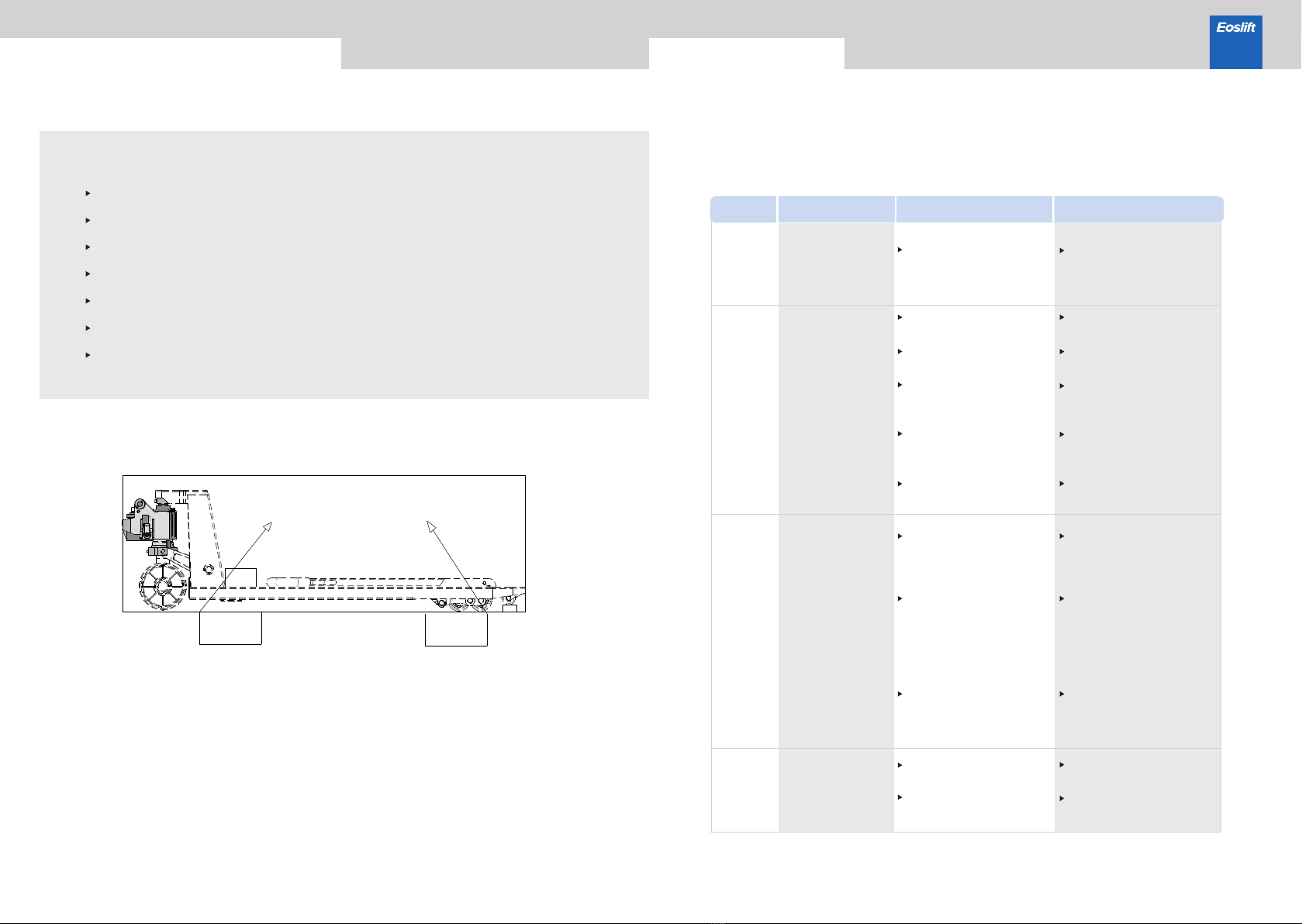
Safety rules
The truck is only applicable to indoor use and the application environment must meet the following conditions:
Free from rainwater or corrosion of harmful gases;
Room temperature of -20°C~+40°C;
Relative ambient humidity <90%;
and Requirements for ground: hard, anti-skid and level without barriers.
Before using the pallet truck, the operator must read the operating instructions and the warning labels on the
truck body carefully.
Do not use this truck on the muddy ground.
Do not operate the pallet truck unless you are fully familiar with it and have been authorized to do so.
Do not operate the pallet truck unless you have carefully checked its condition. Pay special attention to the
wheels, the handle assemblies, the truck frame, the unloading plate, etc.
To pull the truck, always move the finger grip control handle into the middle position. This makes the handle
easier to move and reduces the rebounce of the handle by the small piston. This also preserves the hydraulic
seals and the piston components. A long service life can be expected.
Do not carry or lift passengers.
The operator shall wear safety shoes and gloves for protection.
While the goods are being transported, all people should stay 600mm away from the truck frame.
Do not lift goods in the way as shown in Figure B. Goods should be stacked stably.
Overload is prohibited.
Do not use the truck in a potentially flammable and explosive atmosphere.
Do not use the truck as a vehicle jack.
Do not use the truck during strong wind forces.
Do not use the truck on places insufficiently illuminated.
A B
M Series Hand Pallet Trucks

05 06
1.Hydraulic oil
Please check the oil level every six months and change the oil every twelve months. 32 #
hydraulic oil is recommended, with total volume of about 0.5 liters.
2.Remove the air
The air may enter into the pump because of transportation or pump in upset position. It will cause
the forks fail to be lifted when the finger grip control handle switched to the lifting position. The
air can be removed in the following way: pull the finger grip control handle (1-1) to the lowering
position and move handle up and down for several times.
3.Daily check and maintenance
Daily check and maintenance of the pallet truck can limit wear as much as possible. Special
attention should be paid to the wheels, the axles, as thread, rags, etc.To avoid block the wheels
and axles. The forks should be unloaded and lowered in the lowest position when the job is over.
4.Lubrication
All bearings and pivots are provided with long-life lubricants at the factory. You just need to fill the
lubrication points with long-life lubricants monthly intervals or after each time the truck is cleaned
thoroughly.
1The truck should be parked with the forks lowered to min. height.
2Check if the signs and warning labels on the truck are in place before using the truck each time.
3Use original parts.
4 The waste liquid shall be place in special collection places for disposal.
5 Modifications or alterations to the truck, especially the safety device are prohibited.
6Only customer service persons specially trained by our company can carry out maintenance
of the truck.
7Thoroughly standardized maintenance is the most important preconditions to ensure stable
and reliable operation performance of the truck. Neglect of regular maintenance could result
in failure and malfunction of the truck and poses a potential threat to the safety of the staff and
operation.
Maintenance
1
2
3
1-1
Upper
Middle
Lower
2-3
2-4
2-6
On the handle of this pallet truck, you can find finger grip control handle(1-1) which can be regulated in
three positions :
Lifting-set the control handle at lower position. When lift up the hand pallet truck.
Middle position: set the control handle at middle position. When the operator need to move it.
Lowering: set the control handle at upper position. When lift down the hand pallet truck.
The handle moves back to the middle position when released
However if the truck cannot operate normally as above the three positions, you can adjust them according to the
following steps:
① If the forks elevate while pumping in the Middle position, adjust the adjusting nut (2-4) on the adjusting bolt
(2-3) or screw (2-6) clockwise until pumping action does not raise the forks and the finger grip control handle
works properly Middle position .
② If the forks descend while pumping in the Middle position, the screw(2-6) or nut(2-6) counteradjust
clockwise until the forks stop descending.
③ If the forks do not descend when the finger grip control handle (1-1) is in the Lower position, adjust
the nut (2-4) or screw (2-6) clockwise until the forks. Then check the
Middle position according to steps and ② to make sure the nut (2-4) and screw(2-6) are in the proper①
position.
④ If the forks can’t lift up when the finger grip control handle is in the lower position, adjust the nut
(2-4) or screw (2-6) counterclockwise until the forks lift up. Then check the function of the Lower
position and Middle position according to steps ,②and③ are normal.①
Adjusting the finger grip handle M Series Hand Pallet Trucks
07 08
This chapter enables the user to identify and rectifies basic faults and the effects of incorrect operation.
When trying to locate a fault, proceed in the order shown in the table below. If, after carrying out the
following remedial action listed in “actions”, the truck cannot be restored to operation, contact the
manufacturer’s after-sale service department. Additional troubleshooting must only be performed by the
manufacturer’s specialist service engineers. The manufacturer's customer service department is specially
trained to carry out these operations.
1
Fault Possible cause Action
2
No.
3
4
Troubles shooting
The forks cannot
be lifted to max.
height
The forks cannot
be lifted up
The forks cannot
be lifted down
Oil leakage
The hydraulic oil is
insufficient
Change hydraulic oil
Put the finger grip handle in
the upper position and press
the handle dozens of times
Add the hydraulic oil
Replace the seals
The hydraulic oil has
impurities
Adjusting nut(2-4) or
adjusting screw(2-6) is in
wrong positions
The hydraulic oil is
insufficient
Air enters into the cylinder
Seals damaged
Piston rod or the frame is
deformed resulting from
overloading or cargo
slanting to one side
The forks was kept in raised
position for extended period
of time, then the piston rod
is exposed to the air and gets
rusted , which blocks the
motion of the piston
The adjusting nut(2-4) or
the adjusting screw(2-6) in
wrong positions
Replace the related parts of
the cylinder or the frame with
new ones
Keep the forks at the lowest
position while not in use, and
keep piston rods lubricated in
time
Parts damaged
Seals damaged Replace the seals
Replace the parts
Adjust the adjusting nut(2-4)
or adjusting screw(2-6) to
correct the position
If the truck have to transporte for a long distance, it should be packed in the wooden pallet in order
to avoid collision during transportation.
Transportion, loading, test and storage
The handle should be fixed stably in case sliding and damages and transported by fork truck
or crane.
Before loading, the operator should first check the truck weight, in order to choose the right
crane.
When unloading the truck, the operator should be aware of safety of the surroundings to ensure
the truck slowly unloaded.
If the truck is transported with the forklift, the forklift shall lift and lower slowly to keep the balance
of the truck.
The truck shall be commissioned according to the following function tests: steering, traveling,
loading control and combined functions with rated capacity.
If the truck doesn’t work, please remove the cargo from the frame and move out the truck from
the working area reasonably.
When the truck won’t be use for a long time, the storage environment shall be kept dry and clean,
with forks lift down to their lowest position.
Add the hydraulic oil
M Series Hand Pallet Trucks
Adjust the adjusting nut(2-4)
or adjusting screw(2-6) to
correct the position

09 10
Parts list · Frame
Frame(2.5t, 540×1150-85), 5012
Frame(3.0t, 540×1150-85), 5012
Frame(2.5t, 685×1220-85), 5012
Frame(3.0t, 685×1220-85), 5012
Double -wheel frame(2.5t, 685×1220-75), 5012
Single -wheel frame(2.5t, 685×1220-75), 5012
Double -wheel frame(3.0t, 685×1220-75), 5012
Single -wheel frame(3.0t, 685×1220-75), 5012
Frame(2.0t, 540×1150-85), hot galvanized
Frame(2.5t, 540×1150-85), galvanized
Frame(3.0t, 540×1150-85), hot galvanized
Frame(2.5t, 685×1150-85), galvanized
Frame(2.5t, 685×1220-85), hot galvanized
Frame(2.5t, 685×1220-85), galvanized
Frame for single wheel(2.5t, 685×1220-75), galvanized
Long shaft(540)
Long shaft(685)
Long shaft(540), galvanized
Long shaft(685), galvanized
Connecting rod assembly(2.0t, 540), black
Connecting rod assembly(3.0t, 540), black
Connecting rod assembly(2.0t, 685), black
Connecting rod assembly(3.0t, 685), black
Connecting rod assembly(2.0t, 540), galvanized
Connecting rod assembly(3.0t, 540), hot galvanized
Connecting rod assembly(2.0t, 685), galvanized
Connecting rod assembly(2.0t, 540), hot galvanized
Connecting rod assembly(2.5t, 685), hot galvanized
Cylinder assembly (AC-85), galvanized
Cylinder assembly (AC-75), galvanized
Cylinder assembly (AC-85), with quick lift, galvanized
Cylinder assembly (AC-75), with quick lift, galvanized
Push rod welded (1150), black
Push rod welded (1220), black
1
1
1
1
2
WC02000001
WC02000083
WC02000079
WC02000086
WC02000119
WC02000162
WC02000788
WC02000490
WC02000942
WC02000852
WC02000761
WC02000857
WC02001025
WC02000895
WC02000893
WC02000013
WC02000082
WC02000532
WC02000186
WC02000005
WC02000084
WC02000081
WC02000087
WC02000604
WC02000762
WC02000184
WC02000531
WC02001026
WC01000001
WC01000006
WC01000005
WC01000007
WC02000002
WC02000080
1
2
3
4
5
Qty.
NO. Parts number Description
5
Seals damaged
Impurities in the oil cause
the valve to be unable to
close tightly
The adjusting nut(2-4) or
the adjusting screw(2-6) in
wrong positions
Note: Do not attempt to repair the pallet truck unless you are specially trained.
The forks
lift down without
operation
Change hydraulic oil
Replace the seals
Troubles shooting M Series Hand Pallet Trucks
Adjust the adjusting nut(2-4)
or adjusting screw(2-6) to
correct the position

11 12
WC02000605
WC02000182
WC02001027
WC02000134
WC02000136
WC02000138
WC02000154
WC02000009
WC02000032
WC02000006
WC02000688
WC02000185
WC02000894
WC02000008
WC02000011
WC02000031
WC02000021
WC02000029
WC02000030
WC02000078
WC02000085
WC02000199
WC02000156
WC02000177
WC02000485
WC02000003
WC02000183
WC02000530
WC02000020
WC02000010
WC02000007
WC02000022
WC02000023
WC02000077
5
6
7
8
9
10*
11
12
13
14
15
16
17*
18
19*
Push rod welded (1150), galvanized
Push rod welded (1220), galvanized
Push rod welded (1220), hot galvanized
Push rod welded (1500), black
Push rod welded (1800), black
Push rod welded (2000), black
Push rod welded (2500), black
Connecting shaft for small wheel carrier, galvanized
Connecting base, galvanized
Small wheel carrier (85), black
Small wheel carrier (75), black
Small wheel carrier (85), galvanized
Small wheel carrier (75), galvanized
Plastic washer
Wheel shaft, galvanized
Plastic roller
Guide wheel (into roller 40 × 50 × 10.5)
Iron-core PU wheel φ180×50, bright red PU, black iron core
Aluminium-core rubber wheel φ180 × 50 × 140, black
Nylon wheel φ180×50(flower-shape wheel)
Nylon wheel φ180×50, white(plane wheel)
Aluminium-core PU wheelφ180×50, bright red PU
Aluminium-core rubber wheelφ200×50×160, black
Iron-core PU wheel φ200×50, bright red PU, black iron core
Nylon wheel φ200 × 50, white (flower-shape wheel)
Handle EOS-AC, black
EOS-AC Galvanized steel handle(BZ)
Handel assembly AC-B, hot galvanized
GB308, Steel ball S18
Push rod connecting shaft, galvanized
Rocker, galvanized
GB276, Deep groove ball bearing 6204, two-side shielded
Iron-core PU wheel φ80×70, bright red PU, black iron core
Nylon wheel φ80 × 70, white
2
2
2
2
4
4
2
2
2
1
1
2
4
8
4
Qty.
NO. Parts number Description
Iron-core PU wheel φ74 × 70, bright red PU, black iron core
Nylon wheel φ74 × 70, white
Bolt pin 2, galvanized
Bolt pin, galvanized
Dust cover, galvanized
Big wheel cover, black
Big wheel cover, white
Big wheel shaft, galvanized
Connecting bracket, galvanized
Sliding bearing 29×25×25
Sliding bearing 18×16×15
GB301, thrust ball bearing 51111
GB3452.1, O-ring φ5×1.8
JB7940.2, Angle hydraulic grease nipple M6
GB894.1, Circlip for shaft 16, blackening
GB894.1, Circlip for shaft 20, blackening
GB879.1, Spring type straight pin 8×45, blackening
GB70.1, Hexagon socket head cap screw M6 × 16, galvanized
GB93, Normal type spring lock washer 6, galvanized
GB893.1, Circlip for hole 25, blackening
Connecting shaft, galvanized
JB7940.4, Push-fit type grease nipple 6
GB879.1, Spring type straight pin 5×26, blackening
GB879.1, Spring type straight pin 5×28, blackening
GB879.1, Spring type straight pin 5×32, blackening
GB5780, Hexagon head bolt M10×65, galvanized
GB889.1, Hexagon locking nut M10, galvanized
GB6173, Hexagon thin nut M20×1.5, galvanized
Washer
Iron-core PU wheel φ74 × 93, bright red PU, black iron core
Nylon wheelφ74×93
Single wheel shaft, galvanized
GB894.1, Circlip for shaft 52, blackening
Small wheel carrier (85), black
4
2
2
1
2
1
1
2
4
1
1
1
2
2
1
1
1
2
1
3
2
2
8
2
2
2
4
2
2
1
2
WC02000160
WC02000120
WC02000012
WC02000014
WC02000015
WC02000016
WC02000076
WC02000017
WC02000018
WC02000024
WC02000025
WC02000028
WC02000027
WC02000026
WE07000002
WE07000004
WE06000004
WE03000001
WE05000001
WE07000001
WC02000004
WC02000019
WE06000002
WE06000003
WE06000001
WE01000001
WE04000002
WE04000001
WC02000075
WC02000074
WC02000118
WC02000073
WE07000003
WC02000006
19*
20
21
22
23
24
25
26
27
28
29
30
31
32
33
34
35
36
37
38
39
40
41
42
43
44
45
46
47
48
49*
Qty.
NO. Parts number Description
Parts list · Frame M Series Hand Pallet Trucks

Parts list · Frame
Small wheel carrier (75), black
Small wheel carrier (85), galvanized
Small wheel carrier (75), galvanized
GB879.1, Spring type straight pin 5×32, blackening
GB276, Deep groove ball bearing 6204, two-side shielded
2
8
8
WC02000688
WC02000185
WC02000894
WE06000001
WC02000022
49*
50*
51*
Qty.
NO. Parts number Description
Note:Marked with * are doube wheel parts
24
16
13
18
32
23
21
38
25
40
48
28
22
33
4
37
41
15
14
3
3029
27
31
20
26
2
36
34 35
1
744 5
16
9
8
41
6
11
41
47
45
18
46
18
45
38
9
39
42
12
43
49
10
51
19
51
17
50
13 14
M Series Hand Pallet Trucks
16
15
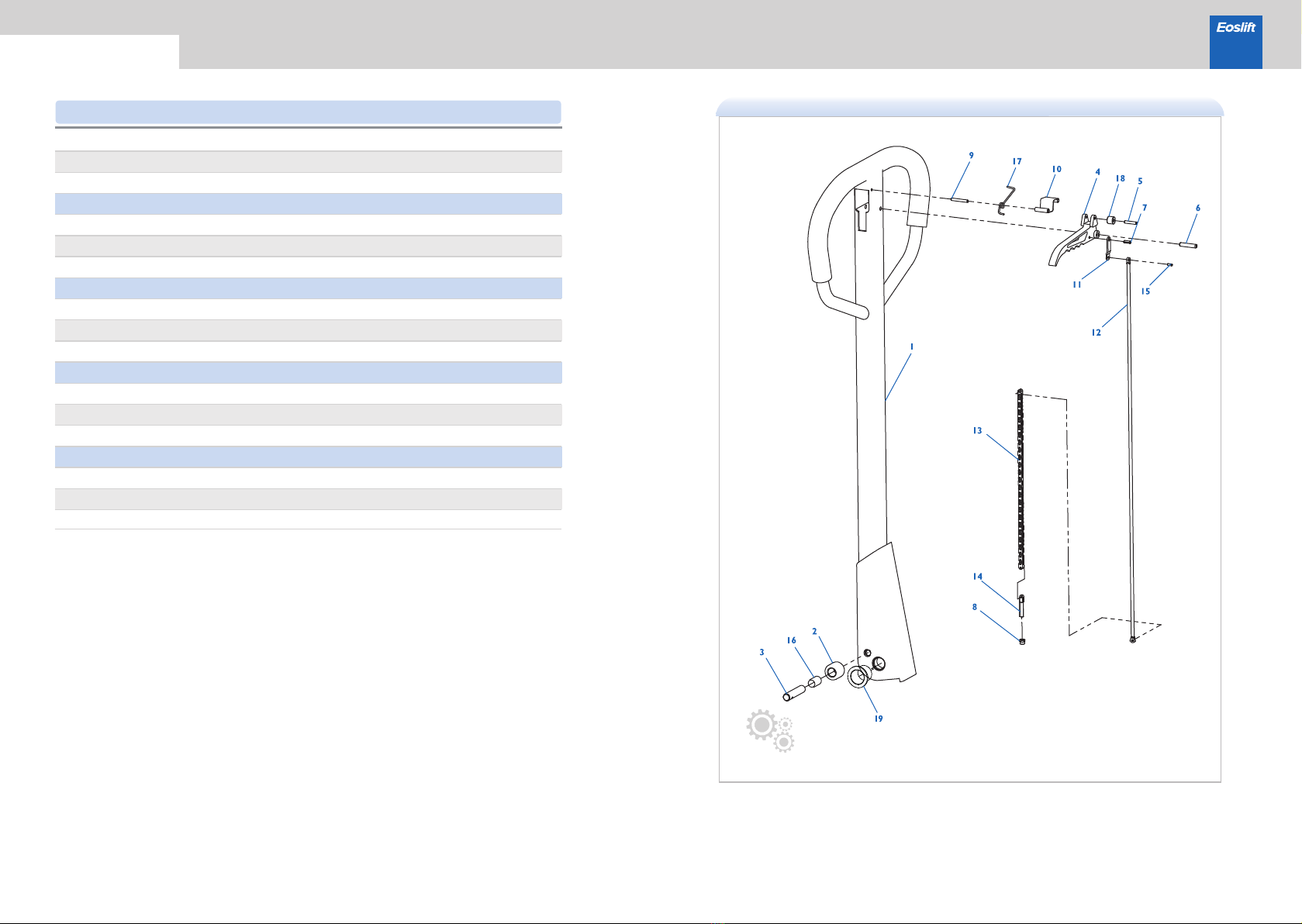
Parts list · Handle M Series Hand Pallet Trucks
1
2
3
4
5
6
7
8
9
10
11
12
13
14
15
16
17
18
19
WJ10800014
WJ10800015
WJ10800016
WJ10800011
WJ10800006
WJ10800003
WJ10800004
WJ10800020
WJ10800002
WJ10800008
WJ10800012
WJ10800013
WJ10800018
WJ10800019
WJ10800005
WJ10800017
WJ10800009
WJ10800010
WJ10800058
Handle welded
Clamping roller
Roller pin
Finger grip handle
Spring type pin (5)
Spring type pin (6)
Spring type pin (7)
Locking nut
Spring type pin (9)
Positioning plate
Connecting sheet of pull rod
Pull rod
Chain
Adjusting bolt
Spring type pin (15)
Bushing
Torsion spring
Plastic roller
Bush (19)
1
1
1
1
1
1
1
1
1
1
1
1
1
1
1
1
1
1
1
Qty.
NO. Parts number Description

18
17
Parts list · Cylinder
*26
M Series Hand Pallet Trucks
Qty.
NO. Parts number Description
Note: Marked with * are optional parts
1
2
3
4
5
6
7
8
9
10
11
12
13
14
15
16
17
18
19
20
21
22
23
24
25
*26
WC02000157
WC02000033
WC02000060
WC02000036
WC02000061
WC02000059
WC02000058
WC02000035
WC02000045
WC02000046
WC02000038
WC02000071
WC02000037
WC02000044
WC02000039
WC02000064
WC02000063
WC02000042
WC02000041
WC02000043
WC02000040
WC02000049
WE06000005
WE03000003
WE04000003
WC01000046
WC02000620
1
1
1
1
1
1
1
1
1
1
1
1
1
1
1
1
1
1
1
1
1
1
1
1
1
1
Valve body welded(75), galvanized
Valve body welded(85), galvanized
GB982, Combination sealing gasket 10
Screw
Seal ring UHS35
GB3452.1, O-ringφ34.5×3.55
Dustproof ring DH35
Piston rod
Safety valve spool
Pressure adjusting spring
Pressure adjusting screw
GB3452.1, O-ring φ11.2×2.65
Screw plug
Copper gasket
Pump body
Seal ring UHS18
Dustproof ring DH18
Spring cover
Pump core
Pressure spring
Pin
Unloading plate, galvanized
GB879.1, Spring type straight pin 8×50, blackening
GB73, Slotted set screws with flat point M8 × 20, galvanized
GB6172.1, Hexagon thin nut M8, galvanized
Integrated valve assembly
Unloading plate, galvanized

19 20
Parts list · Integrated valve M Series Hand Pallet Trucks
Qty.
NO. Parts number Description
1
2
3
4
5
6
7
8
9
10
11
12
13
14
15
16
17
18
19
WC02000051
WC02000065
WC02000067
WC02000053
WC02000066
WC02000050
WC02000052
WC02000054
WC02000069
WC02000070
WE06000006
WC02000055
WC02000062
WC02000048
WE03000002
WC02000056
WC02000057
WC02000047
WC02000068
Push pin sleeve
GB3452.1, O-ringφ15.2×2.4
GB3452.1, O-ringφ8×1.8
Return valve sleeve
GB3452.1, O-ringφ9.5×1.8
Stem
Unloading spring
O-ring retainer Ⅱ
GB308, Steel ball S7
Liquid inlet valve sleeve
GB117, Copper taper pin 2 × 5
O-ring retainerI
GB3452.1, O-ringφ13.2×2.4
Spring leaf
GB818, Pan head screw with cross recess M2×2, galvanized
Boost valve spool
Spool spring
Blind nut
GB3452.1, O-ring φ21.2×2.65
1
1
2
1
1
1
1
1
1
1
2
1
1
1
1
1
1
1
1
31
26
25
24
23
22
19
21
20
18
17
1
2
3
4
5
6
8
9
10
11
12 7
16
27
28
14
15
13
30
29
21
M Series Hand Pallet Trucks
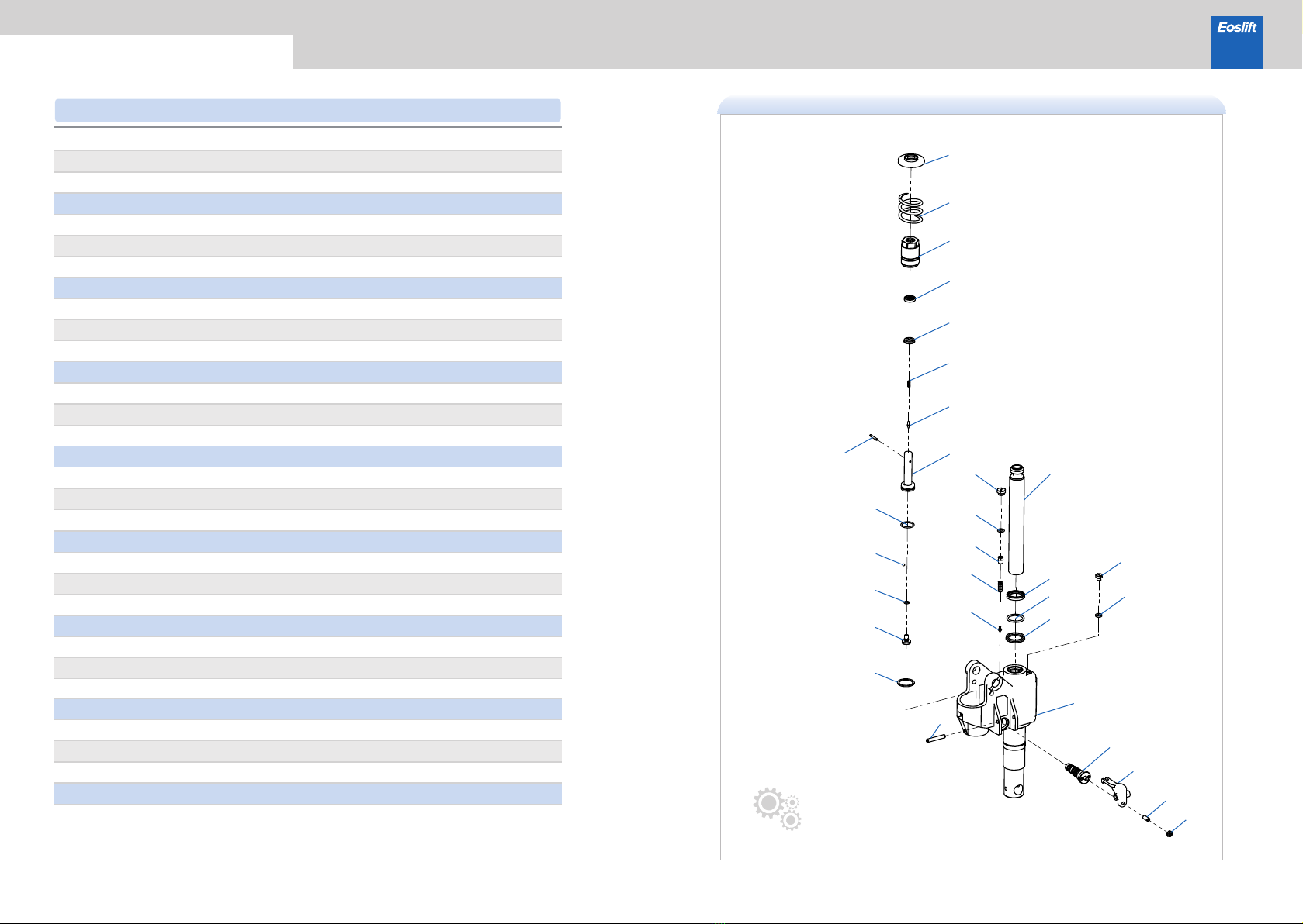
Parts list · Quick lift cylinder
1
2
3
4
5
6
7
8
9
10
11
12
13
14
15
16
17
18
19
20
21
22
23
24
25
26
27
28
29
30
31
WC02000121
WC02000723
WC02000060
WC02000036
WC02000061
WC02000059
WC02000058
WC02000035
WC02000045
WC02000046
WC02000038
WC02000071
WC02000037
WC02000122
WC02000064
WC02000063
WC02000123
WC01000046
WC02000049
WE06000005
WE03000003
WE04000003
WC02000126
WC02000127
WC02000132
WC02000129
WC02000131
WC02000128
WC02000130
WC02000124
WC02000125
WE06000011
Valve bodyseaming part(AC-85), quick lift pump, galvanized
Valve bodyseaming part(AC-75), with quick lift, galvanized
GB982, Seal washer 10
Bolt
Seal ring UHS35
GB3452.1, O-ringφ34.5×3.55
Dusty seal ringDH35
Piston rod
Safety valve
Pressure spring
Pressure adjusting screw
GB3452.1, O-ringφ11.2×2.65
Screw
Quick lift pump body
Seal ring UHS18
Dusty seal ringDH18
Quick lift pump pistion
One valve assembly
Unloading plate, galvanized
GB879.1 Pin 8×50, black
GB73 Screw M8×20, galvanized
GB6172.1 Hex nut M8, galvanized
Copper gasket
Quick lift blind nut
GB3452.1, O-ringφ9.0×1.8
GB308, Steel ball S5
GB3452.1, O-ringφ27×3
Centre
Spring
Spring cover
Pressure spring
GB119.1 Pin 4×28, galvanized
1
1
1
1
1
1
1
1
1
1
1
1
1
1
1
1
1
1
1
1
1
1
1
1
1
1
1
1
1
1
1
Qty.
NO. Parts number Description
22
This manual suits for next models
12
Other Eoslift Truck manuals


Popular Truck manuals by other brands


Hamron
Hamron 325-001 operating instructions

Komatsu
Komatsu Galeo HD325-6 brochure

Jungheinrich
Jungheinrich ETX ac 125 operating instructions

Mitsubishi
Mitsubishi Fuso FK/FM 2006 owner's manual

chevrolet truck
chevrolet truck Light Duty Truck 1994 Series Repair manual

HERKULES
HERKULES AHW 2500/1 Original operating instructions