Big Joe PDM-20-154 User manual

Document 367 1
06/12/06
PDM
SUPPLEMENT
CIRCUIT CITY
PDM-20-154
Table 1. Serial Number Effectivity
1. GENERAL
This document supplements the basic PDM Manual
No. 901356 and provides additional operating, safety
and maintenance information.
Additional standard equipment of the platform, strobe
light, a lowering buzzer, an emergency lowering valve,
a keyswitch, an emergency power disconnect (EPD),
a safety belt, and a self-retracting lifeline.
TRUCK MODEL SERIAL NUMBERS
PDM Equipped With Special Features 375784 AND HIGHER
IMPORTANT
Ultra-deep discharging of brand new batteries should be avoided for at least 15 cycles.
These batteries have a superior deep cycle life. However, to dramatically extend battery life, ultra-deep
discharge should be avoided. The shallower the average discharge, the longer the life.
If the batteries are continually undercharged, performance is reduced and life is shortened.
THESE BATTERIES ARE MAINTENANCE-FREE. ANY ATTEMPT TO OPEN THE BAT-
TERY WILL VOID WARRANTY.

1Miller® is a registered trademark of Miller Equipment, Franklin PA.
2DBI/SALA® is a registered trademark of DBI/SALA, Red Wing, MN.
2Document 367
2. SAFETY PRECAUTIONS
The following safety precautions must be adhered to
at all times.
• All warnings and instructions must be read and
understood before using the equipment.
• Equipment must not be altered in any way.
• Equipment must be inspected by a qualified person
on a regular basis.
• Be certain that required restraining means such as
safety belts, lifelines, and chains are properly used.
• Safety belt buckles must be visually inspected to
assure proper and secure connection before use.
• The self retracting lifeline should be attached to the
back Dee ring only on the safety belt.
• Replace any safety belt or life line that sustains per-
manent deformation or is otherwise damaged.
• Be certain that the lifting mechanism is operating
smoothly throughout its entire lift height, both empty
and loaded.
• Be sure that mast is vertical--do not operate on a
side slope.
• Be sure the platform is not tilted forward or rearward
when elevated.
• Be sure the truck has a firm and level footing.
• Before personnel are elevated, mark area with
cones or other devices to warn of work by elevated
personnel.
• Avoid overhead wires and obstructions.
• Personnel are to remain on the platform floor. Use of
railings, planks, ladders, etc., on the platform for pur-
pose of achieving additional reach or height is pro-
hibited.
• Personnel and equipment on the platform must not
exceed the available space.
• Lower platform to floor level for personnel to enter
and exit. Do not climb on any part of the truck in
attempting to enter and exit.
3. CONTROLS AND INDICATORS
Steering Control Head of the truck is covered in
Supplement 220.
A remote lift, lower and stop switch is located on the
platform as shown in Figure 1. An emergency power
disconnect (EPD), keyswitch and an emergency low-
ering valve are located on the rear of the truck as
shown in Figure 1.
4. OPERATING PROCEDURES
WARNING: Understand truck limitations and oper-
ate the truck in a safe manner so as not
to cause injury to personnel. Safeguard
pedestrians at all times. Be sure you
have read and understand the Safety
Precautions listed in paragraph 2.
Users shall comply with all requirements indicated in
applicable OSHA Standards and current edition of
A.N.S.I. B56.1 Part II. By following these requirements
and the requirements in this supplement you will get
many years of safe, dependable service from your Big
Joe lift truck.
The basic operation of the truck is covered in the PDM
Manual No. 901356. Steering Control Head operation
of the truck is covered in Supplement 220. Refer to the
Miller®1Equipment manual supplied with this truck for
information on the proper use, safety precautions and
maintenance procedures applicable to the Safety Belt.
Refer to the DBI/SALA®2Operation and Maintenance
manual supplied with this truck for information on the
proper use, safety precautions and maintenance pro-
cedures applicable to the Self Retracting Lifeline. Prior
to operating the truck a check of safety items should
be performed to insure the operating integrity of these
items.
Document 367 3
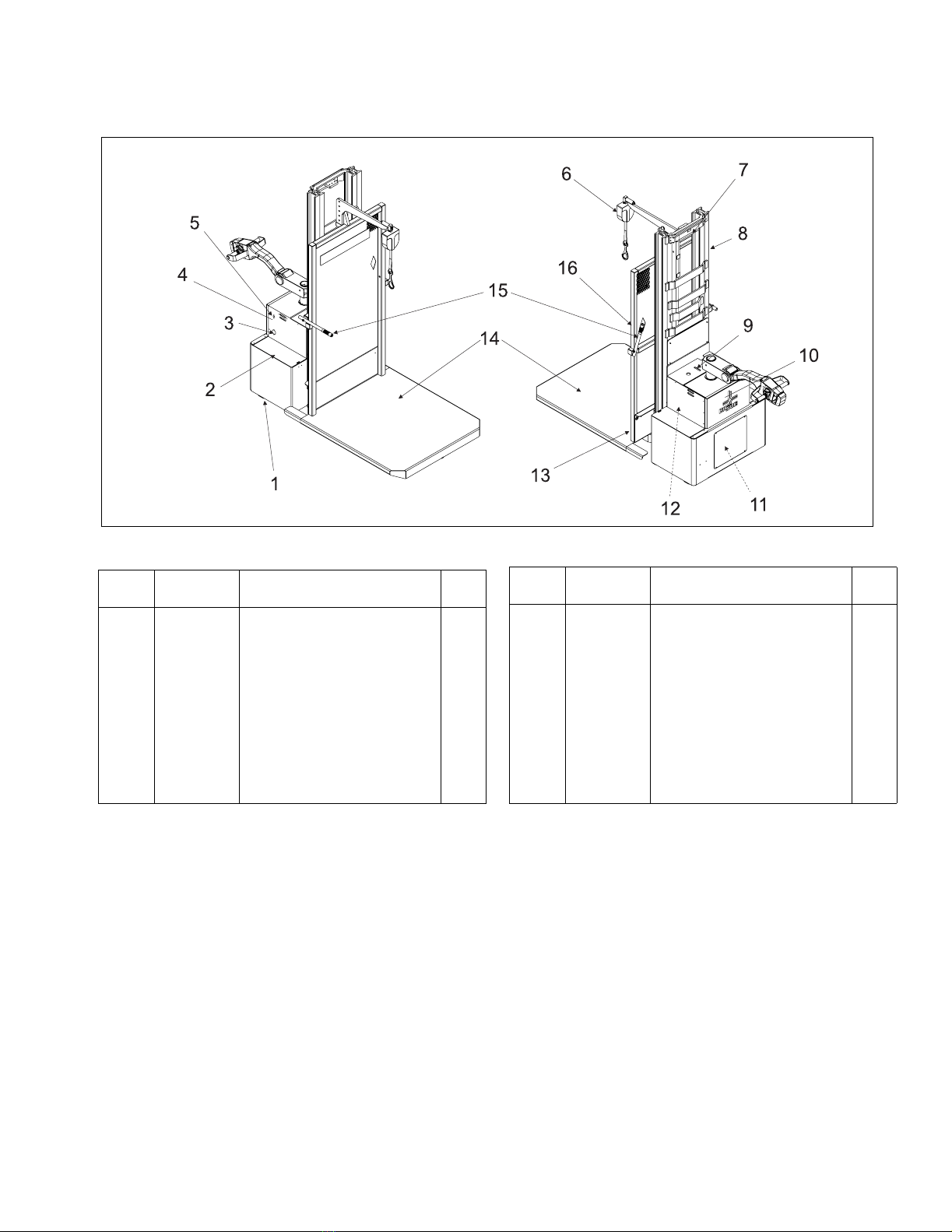
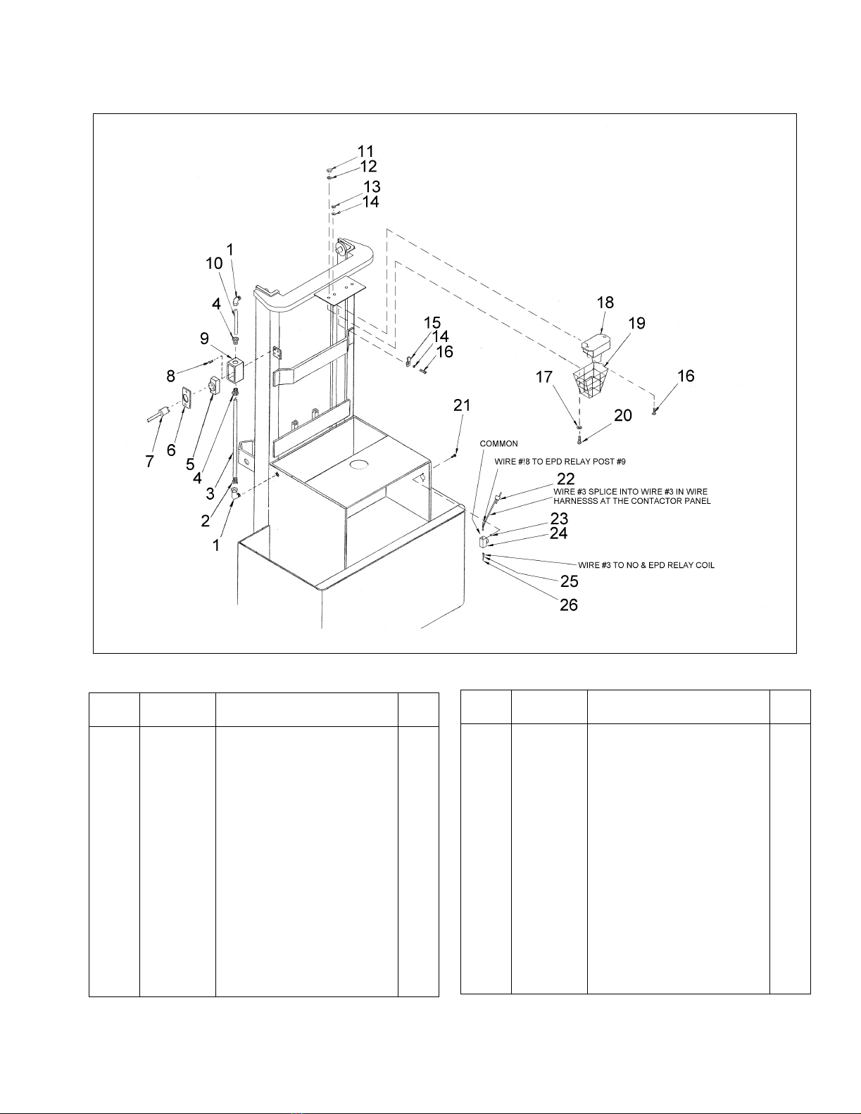
Figure 1. Location of Special Items
R6287
INDEX
NO.
PART
NO.
PART NAME NO.
REQ.
1 054412 CASTER 2
2 003216 BATTERY 2
3 — BATTERY CHARGER (FIGURE 3)REF
4 20574 DECAL 1
5 020698 SWITCH, EPD ENGAGE 1
6 — BOOM (FIGURE 18)REF
7 — STROBE LIGHT (FIGURE 9)REF
8 — ELEVATION SYSTEM (FIGURE 17)REF
9 23742 DECAL 1
INDEX
NO.
PART
NO.
PART NAME NO.
REQ.
10 — HYDRAULIC SYSTEM
(FIGURE 14)
REF
11 — EPD CONTACTOR BOX
(FIGURE 13)
REF
12 — ELECTRICAL PANEL ASSEMBLY
(FIGURE 7)
REF
13 — LOWERING BUZZER (FIGURE 11)REF
14 506268 CARRAGE AND PLATFORM 1
15 — GRAB HANDLE (FIGURE 18)REF
16 — REMOTE CONTROL (FIGURE 10)

4Document 367
4.1. Safety Check
The following safety checks should be made at least
once each day to verify operation of safety devices.
Also perform the daily checks in the basic PDM Man-
ual No. 901356, paragraph 2-3. If any malfunctions are
found, do not use the truck until repairs are made.
1. Verify that platform chains are present and func-
tional.
2. Verify that the flashing red light operates when the
keyswitch is engaged.
3. Verify that buzzer sounds when the DOWN button
on the platform is pressed.
4. Verify that the safety belt and self-retracting lifeline
are present, installed with locking carabiner (when
applicable), and functioning properly.
5. Verify that the travel defeat switch disables the
steering arm when the platform is raised.
6. Verify that the emergency lowering valve is func-
tioning properly.
WARNING: Do not operate with platform railing
chains missing or not functioning.
4.2. Load Rating
Trucks are designed to handle loads up to 650 pounds
at a 19" load center. Loads include personnel. Always
carry loads as far back as possible on the platform.
Refer to basic PDM Manual No. 901356, paragraph
2-2 and Figure 2-1.
WARNING: Exceeding the load rating specified
above can cause the truck to tip resulting
in possible injury.
4.3. Special Operating Information (Figure 1)
1. When the truck power is disconnected by the bat-
tery disconnect, the Emergency Power Disconnect
(EPD) will automatically disengage. To reset, con-
nect the battery and momentarily press the EPD
Engagement switch. If the EPD does not operate
refer to paragraph 6.9.
NOTE: If the EPD will not reset, there may be
another electrical open or loose connection.
2. The keyswitch should be turned to the off position
and the key removed when the truck is left unat-
tended. Turning off the keyswitch reduces battery
discharge.
3. A travel defeat switch completely disables the
steering arm when the platform is raised.
4. The platform can be raised and lowered using the
remote switch box located on the platform.
5. When the platform is lowered, a buzzer will sound.
6. The emergency lowering valve can be used to
lower the platform when conditions require it's
use.
7. If the platform hangs up on a shelf or obstruction
during lowering, a hang-up valve will stop the cyl-
inder from lowering further. Raise the platform to
eliminate the hang-up contact before moving truck
to clear obstruction.

Document 367 5
5. PLANNED MAINTENANCE
Refer to the basic PDM Manual No. 901356 Chapter 3
for basic planned maintenance procedures. Ta b l e 2
indicates additional planned maintenance tasks which
should be performed on a quarterly basis. These
maintenance procedures should be performed only by
qualified service personnel.
Table 2. VISUAL CHECKS
ITEM PROCEDURE
Check all fluids and lubrication points. Refer to PDM manual paragraph 3-4
Check lift chains Check for damage and adjustment. If adjustment is necessary refer
to PDM manual Chapter 8
Check sheaves and bearings. Check for damage or binding.
Check cable in pivot tube. Check for excessive wear around spring tube assembly and where
cable exits pivot tube.
Check brake linkage and pads for wear. Refer to PDM manual Chapter 6 to replace worn linkage or pads.
Check lift cylinder for leakage. Raise cylinder to fully elevated position. Disconnect drain line and
observe amount of oil coming from cylinder fitting. If more than a
couple of drops of oil is forced out of gland, change packing. Refer
to Figure 16.
Check hydraulic system filter and breather. Replace if dirty.

6Document 367
6. MAINTENANCE
Refer to the basic PDM Manual No. 901356 for all
general service information. Refer to Figure 1 for the
location and identification of items not listed in the
basic manual.
6.1. Battery Part Number 003216
These Gel Cell Batteries are maintenance-free. Any
attempt to open the battery will void the warranty.
Ultra-deep discharging of brand new batteries should
be avoided for at least 15 cycles. To dramatically
extend battery life, ultra-deep discharge should be
avoided. The shallower the average discharge, the
longer the battery life.
6.1.1. Charging Batteries
Charging requirements will vary depending on depth of
discharge and temperature. Follow safety rules when
placing a battery on charge.
Proceed as follows:
1. Park truck at charging station with platform low-
ered and key switch off.
2. Check the condition of the AC cord, the battery
connector and battery cables. If there are any cuts
in the cable, any exposed wires, loose plugs or
connectors, DO NOT attempt to charge the batter-
ies. Contact appropriate personnel for repairs to
be made.
3. Disconnect the batteries from the truck and con-
nect batteries to the charger. Make sure connec-
tors are mated properly.
4. Connect the AC cord to the truck and then plug
into the 120 Volt AC power supply.
5. The battery charger is fully automatic and will
cycle automatically (depending on amount of
charge needed). Charge status can be observed
as follows (Refer to Figure 2):
a. The top three LED’s indicate charger status.
At start of charge the RED (Charge) LED will
be ON indicating the batteries are connected
and charging. After the batteries charge to
approximately 80% the Yellow LED comes
ON. After a time (1 hour minimum) the Green
LED comes ON indicating battery ready.
NOTE: The battery charger includes an
override timer which terminates the
charge if the cycle does not complete
after 18 hours of charging. This time-
out condition is indicated by the
green LED flashing off and on, and it
indicates a fault condition which
should be investigated. This will
occur if the charger cannot raise the
battery voltage to the preset voltage
limit. Possible causes indicate a bat-
tery fault, a charger fault, low AC
power supply voltage, or excessive
discharge. The override timer can be
reset by switching the AC power to
the charger off.
b. The lower four red LED’s indicate current flow.
Normally at start of charge, if the batteries are
discharged, all four red LEDs will be on indi-
cating maximum 25A charge current. As the
batteries charge the current drops and the
LEDs go OFF as the current drops to 20A,
15A, 10A and 5A respectively.
Figure 2. Charge Indicator
R6114

Document 367 7
6.1.2. Removing Batteries from Charger
1. The Green “READY“ LED stays on until the
charger is unplugged from AC outlet.
2. Disconnect AC plug from the power supply and
then remove it from the truck.
3. Disconnect the batteries from the charger and
connect the batteries to the truck. Make sure con-
nectors are mated properly.
6.2. Electrical System
Refer to the basic PDM Manual No. 901356 for all
general service information. Refer to Supplements 220
for general information for the Steering Control Head.
Refer to Figure 6 in this document for the wiring dia-
gram of truck.
R6115
8Document 367
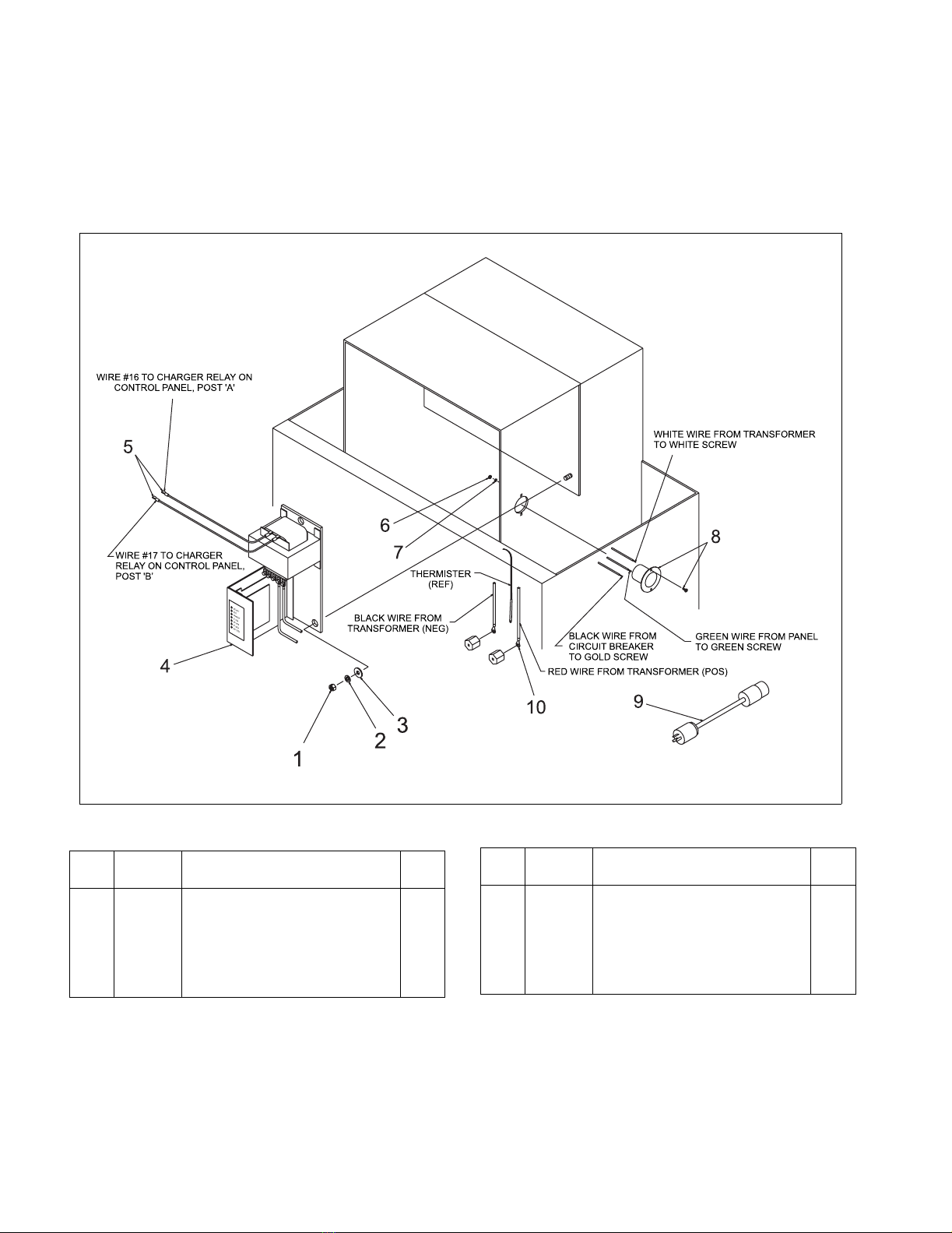
6.3. Battery Charger
The 23840 battery charger is located inside the cover
in front of the steering arm as shown in Figure 1. Refer
to Figure 3 for charger installation and Figure 4 for dis-
assembly and part number information.
Figure 3. Battery Charger Installation
R6286
INDEX
NO.
PART
NO.
PART NAME NO.
REQ.
1 059529 NUT, HEX, JAM, 3/8-16 2
2 077211 WASHER, LOCK, SPLIT, 7/16 2
3 077056 WASHER, FLAT 2
4 — CHARGER (FIGURE 4)REF
5 021249 TERMINAL 2
INDEX
NO.
PART
NO.
PART NAME NO.
REQ.
6 059412 NUT - HEX, 6-32 2
7 077204 WASHER - LOCK, SPLIT, #6 2
8 005454 CONNECTOR - INLET, FLANGED 1
9 005810 CORD ASSY - EXTENSION, 120V 1
10 021238 TERMINAL 2

Document 367 9
Figure 4. Battery Charger
R6288
INDEX
NO.
PART
NO.
PART NAME NO.
REQ.
— 23840 CHARGER, 24 VOLT 1
1 056681 . DECAL, CHARGER, LED 1
2 023018 . WIRE, 16 GA, BLACK 30”
3 23831 . PANEL 1
4 023000 . WIRE, 16 GA, WHITE 16”
5 023004 . WIRE, 16 GA 16”
6 023018 . WIRE, 16 GA, BLACK 16”
7 021237 . TERMINAL RING 2
8 021207 . TERMINAL RING 1
9 023010 . WIRE 30”
10 023011 . WIRE 30”
— 004987 . CHARGER KIT-24V, 25 AMP 1
INDEX
NO.
PART
NO.
PART NAME NO.
REQ.
11 904075 . . PCB ASSY WITH HEATSINK 1
12 904074 . . . THERMISTOR 1
13 003403 . . CIRCUIT BREAKER, AUTO RESET 1
14 904076 . . TRANSFORMER 1
15 071376 . SCREW, TRUSS, #10-32 X 1/2 2
16 077208 . WASHER, LOCK, SPLIT, #12 3
17 059416 . NUT, HEX, 10-32 3
18 021218 . TERMINAL, RING, #4 CABLE, 3/8” 4
19 070475 . SCREW, PH RD HD, 1/4-20 X 3/8 4
20 077209 . WASHER, LOCL, SPLIT, 1/4 4
21 077031 . WASHER, 5/16 X 3/4 X 16 GA 5
22 077032 . WASHER, 3/16 X 1/2 X 13 GA 1
10 Document 367
6.4. Battery Charger Troubleshooting
Refer to Figure 6 for part identification. Be sure the
batteries are connected to the charger and the AC
cord is connected to 120 VAC power supply.
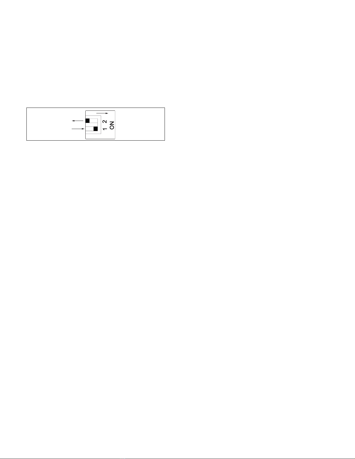
6.4.1. Dip Switch Setting (Figure 5)
The DIP switch on the Printed Circuit Board (PCB)
must be set for Gel Cell Batteries. Check that switch 1
is be ON and switch 2 is be OFF.
Figure 5. Dip Switch Settings
6.4.2. Thermistor
There is a temperature sensing thermistor plugged
into a 2-pin socket marked THERM on the PCB.
Check that this is firmly connected or the battery volt-
age control will not work properly.
6.4.3. Circuit Breaker Testing
Using a multimeter set to measure 120 VAC, check
each side of the circuit breaker to ground. If 120 VAC
was not indicated on both sides, replace the circuit
breaker.
6.4.4. Power Transformer Testing
The two 0.250” tabs on the primary side of the trans-
former and the five #10 screw lugs on the secondary
side. Test the transformer as follows:
1. Using a multimeter set to measure at least 120
VAC, verify that AC Power supply 120V 60Hz
input is present at the transformer primary termi-
nals. If 120 VAC was not indicated, check the cir-
cuit breaker and wiring.
2. Using a multimeter set to measure at least 50
VAC, verify the transformer secondary terminals
as follows:
a. Verify 25 VAC from blue wire to each white
wire.
b. Verify 50 VAC from the white wire to white
wire.
c. If these voltages were not indicated, replace
the transformer.
6.4.5. Circuit Board Testing
The circuit board has a built in diagnostic test at
power-up.
1. Switch the AC supply OFF and then ON, watching
the 3 upper LEDs on the PCB. The 3 LEDs should
light briefly in sequence Green-Yellow-Red when
power is applied. This indicates the transformer is
OK and that power is getting to the PCB.
2. If the battery DC is connected to the charger cor-
rectly, the Red LED should come ON immediately
after this test sequence.
3. If the Green-Yellow-Red LED test sequence does
not show at power-up, or if it cycles constantly
Green-Yellow-Red, the PCB assembly should be
replaced.
4. If the Red or Yellow charging LED does not stay
ON after the test sequence, check that the batter-
ies are connected to the charger.
5. Using a multimeter set to measure at least 30
VDC, verify DC Voltage from Black to Red wire is
as follows:
a. If the Red charging LED is on and the Yellow
charging LED is off, voltage from black to red
wire should be at least 24 VDC.
b. If the Red and Yellow charging LEDs are on,
voltage should be 29 ±1 VDC.
c. If there is no Voltage, check the wiring and
connections from the charger to the battery
terminals. Battery Voltage must be correct
polarity and more than 1 Volt to commence
charging.
R6120

Document 367 11
NOTES

12 Document 367
Figure 6. Wiring Diagram (Sheet 1)
R6289A

Document 367 13
Figure 6. Wiring Diagram (Sheet 2)
R6289B


Document 367 15
INDEX
NO.
PART
NO.
PART NAME NO.
REQ.
— 23836 PANEL ASSY-ELECT,
TRANSISTOR
1
1 506044 . PANEL WELDMENT 1
2 008904 . FUSEHOLDER 1
3 008910 . FUSE, 15 AMP 1
4 068177 . SCREW-RH HD, 5-40 X 3/8 5
5 077203 . WASHER-LOCK, SPLIT, #5 5
6 077007 . WASHER-FLAT 4
7 056504 . DECAL, FUSE, 15 A 1
8 023262 . HARNESS ASY - WIRE, PANEL 1
9 005422 . CONNECTOR, IN-LINE 6
10 23837 . CABLE ASSY - LIMIT SWITCH 1
11 018411 . RELAY-AC 1
12 305407 . BUS BAR 1
13 070491 . SCREW, RD HD, 8-32 X 7/8 4
14 077205 . WASHER - LOCK, SPLIT, #8 4
15 077032 . WASHER-FLAT, 3/16 ID 4
16 005657 . CONTACTOR, 24V 2
17 504150-15 . CABLE ASSY - BUSS 4
18 504150-21 . CABLE ASSY - MTR A2 1
19 504150-22 . CABLE ASSY - MTR S2 1
20 504150-23 . CABLE ASSY - MTR A1 1
21 504181-47 . CABLE ASSY - B+ 1
22 504181-10 . CABLE ASSY - MTR S1 1
INDEX
NO.
PART
NO.
PART NAME NO.
REQ.
23 504150-01 . CABLE ASSY - A2 1
24 505084-14 . CABLE ASSY - POS 1
25 505181-50 . CABLE ASSY - NEG 1
26 063552 . SCREW, HX HD, 5/16-18 X 5/8 3
27 077210 . WASHER - LOCK, SPLIT, 5/16 4
28 059426 . NUT-HEX, 5/16-18 4
29 063553 . SCREW, HX HD, 5/16-18 X 3/4 1
30 005468 . CONTROLLER - SPEED, 24V 1
31 069477 . SCREW, FL HD, 1/4-20 X 1/2 2
32 010614 . STANDOFF-INSULATOR 2
33 077105 . WASHER - BRONZE 4
34 077209 . WASHER - LOCK, SPLIT, 1/46 5
28 059426 . NUT-HEX, BRASS 1/4-20 2
36 075620 . STUD-THREADED, 1/4-20 2
37 070475 . SCREW-RH HD, 1/4-20 X 3/8 5
38 008906 . FUSE, 300 AMP 1
39 056507 . DECAL, FUSE, 300 AMP 1
40 005976 . DIODE 2
41 018409-02 . RELAY-DC 1
42 505321 . SUPPRESSOR ASSY 1
43 021204 . TERMINAL - SLIDE CLIP, 1/4 4
44 021249 . TERMINAL 1
45 023001 . WIRE - 16 GA RED A/R
46 21548 . RESISTOR ASSY - 2700 OHMS 1
16 Document 367
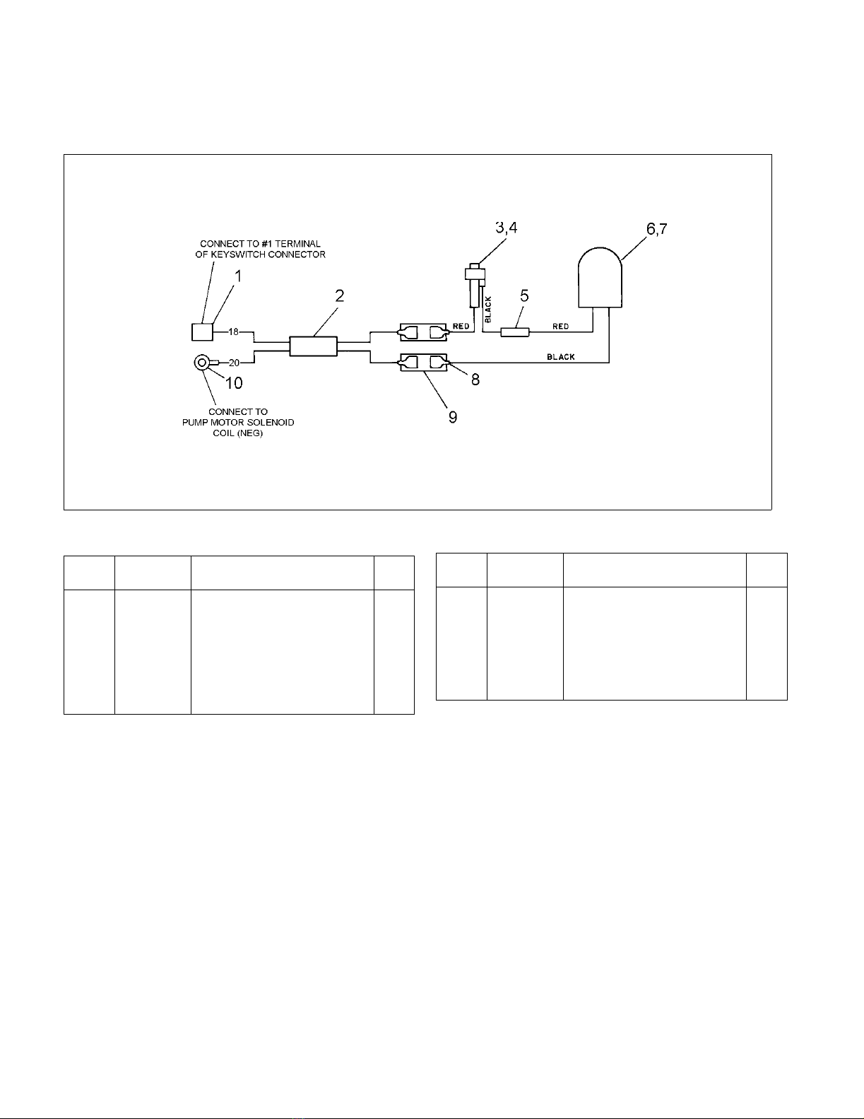
6.6. Flashing Red Light
The Flashing Red Light is located on the Mast as
shown in Figure 1.
Refer to Figure 8 and Figure 9 for part number and wir-
ing information.
Figure 8. Flashing Light Wiring Diagram
R6291
INDEX
NO.
PART
NO.
PART NAME NO.
REQ.
1 005649 CONNECTOR 1
2 20624 WIRE BUNDLE 1
3 901470 FUSE AND FUSE HOLDER 1
4 901469 . FUSE 2 AMP (IF EQUIPPED) 1
5 005433 CONNECTOR 1
INDEX
NO.
PART
NO.
PART NAME NO.
REQ.
6 013609-02 FLASHING RED LIGHT 1
7 904186 . BULB 1
8 021204 TERMINAL 4
9 005422 CONNECTOR 2
10 021203 TERMINAL 1
Document 367 17
Figure 9. Flashing Red Light, Remote Control Conduit and EPD Reset Button
R6292
INDEX
NO.
PART
NO.
PART NAME NO.
REQ.
1 005318 ELBOW 2
2 023014 WIRE BUNDLE 1
3 005311 CONDUIT AR
4 005317 CONNECTOR 1
5 005321 OUTLET 1
6 005320 COVER 1
7 — PLUG (FIGURE 10)REF
8 071379 SCREW 4
9 005315 CONDUIT BOX 1
10 20414 CONDUIT, 1/2” 1
11 059421 NUT 2
12 077209 WASHER 2
13 059416 NUT 2
INDEX
NO.
PART
NO.
PART NAME NO.
REQ.
14 077207 WASHER 3
15 056122 CLIP 1
16 071376 SCREW 3
17 077031 WASHER 2
18 — FLASHING RED LIGHT
(FIGURE 8)
REF
19 013610 GUARD 1
20 063480 SCREW 2
21 069465 SCREW 2
22 005649 CONNECTOR 1
23 074712 WASHER 2
24 020698 EPD RESET BUTTON 1
25 021718 TERMINAL 2
26 023018 WIRE A/R
18 Document 367
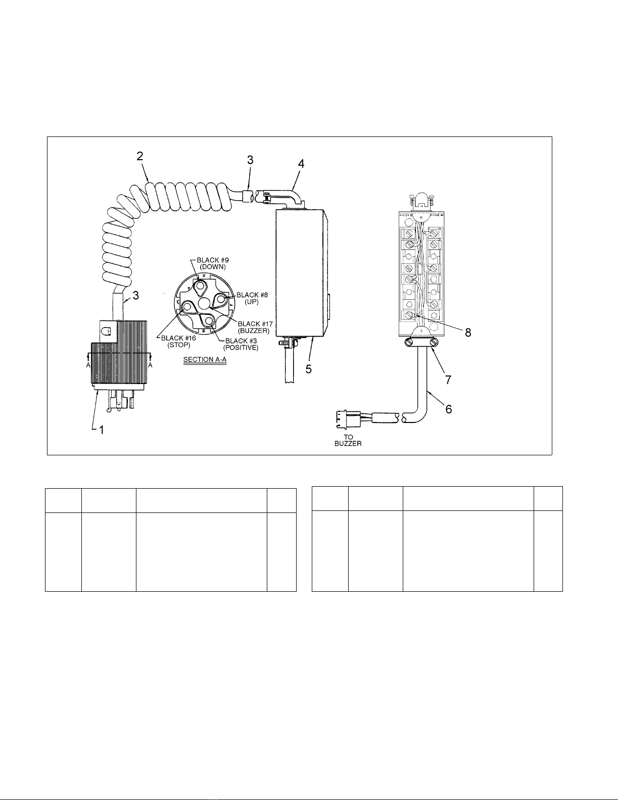
6.7. Platform Remote Control Box
The Remote Control UP DOWN STOP push-button
switch box assy 11151 is located on the Platform as
shown in Figure 1.
Refer to Figure 9 and Figure 10 for part number and
wiring information.
Figure 10. Remote Control Box
R6294
INDEX
NO.
PART
NO.
PART NAME NO.
REQ.
— 11151 REMOTE CONTROL SWITCH BOX
ASSY
1
1 017815 . PLUG 1
2 907199 . CABLE KIT 1
3 278600 . . TUBING AR
INDEX
NO.
PART
NO.
PART NAME NO.
REQ.
4 005451 . CONNECTOR 1
5 020785 . CONTROL BOX 1
6 907175 . CABLE ASSY 1
7 005405 . STRAIN RELIEF 1
8 021210 . SPADE TERMINAL 6

Document 367 19
6.8. Platform Buzzer
The platform lowering buzzer housing is located near
the front lower edge of the platform as shown in Figure
1. Refer to Figure 10 and Figure 11 for part number
information.
Figure 11. Buzzer and Housing
R6293
INDEX
NO.
PART
NO.
PART NAME NO.
REQ.
1 063478 SCREW 1
2 077209 WASHER, LOCK 1
3 11874 GUARD 1
4 800257 CLAMP 1
5 059421 NUT 1
6 11590 BUZZER 1
INDEX
NO.
PART
NO.
PART NAME NO.
REQ.
7 077203 WASHER, LOCK 2
8 068180 SCREW 2
9 056113 TIE, WIRE 1
10 — CABLE (FIGURE 10)REF
11 056111 TIE, WIRE 1
20 Document 367
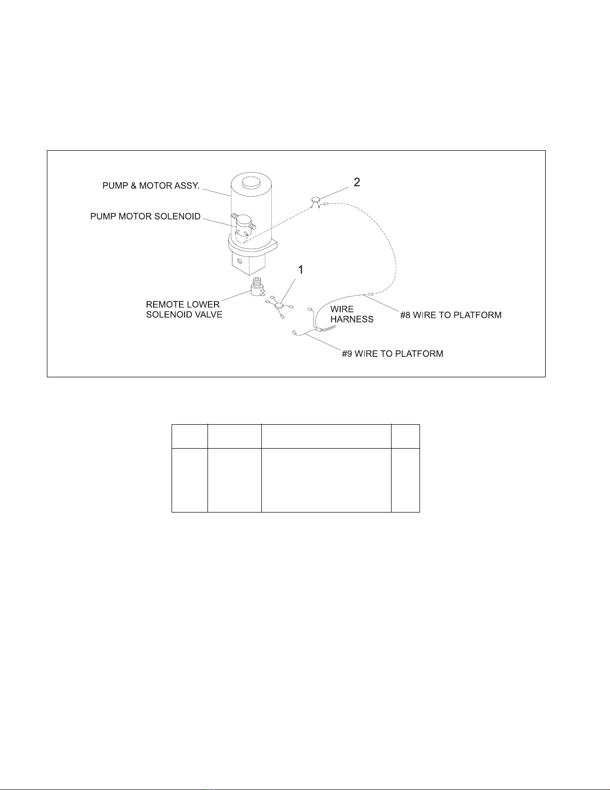
6.8.1. Spike Suppressor & Diode Assy
The 505837 suppressor and diode assembly is
located on remote lowering valve solenoid which is
mounted on the bottom of the hydraulic pump as
shown in Figure 12.
Figure 12. Spike Suppressor & Diode Assys.
INDEX
NO.
PART
NO.
PART NAME NO.
REQ.
1 505837 SPIKE SUPPRESSOR & DIODE
ASSY
1
2 505921 SPIKE SUPPRESSOR & DIODE
ASSY
1
R6295
Table of contents
Other Big Joe Truck manuals


