Eoslift H10 User manual
H10/15/20
Operating Instructions
Manual
Pallet
Stacker
Hotline: 400-626-9090
Tel: +86 573 8622 9999
Fax: +86 573 8622 2900

For proper and safe operation of the products, before
using the products, be sure to read the operating
instructions carefully and retain them properly for
future reference.
The operator needs to have proficient operation skills.
The operator has responsibility to carefully understand
the performance and safety rules of the pallet stacker.
If you have any doubts during the application, please
don't hesitate to contact Eoslift.
Esteemed users:
H10/15/20 Series Manual Pallet Stackers

Ⅰ.Technical parameters 01
Ⅱ. Safe operating rules 02
Ⅲ.Maintenance 03
Ⅳ.Adjusting the finger grip handle 05
Table of contents
Ⅵ.Troubleshooting 07
Ⅶ.Parts list 09
Ⅴ.Transport, loading, test run and storage
06
H10/15/20 Series Manual Pallet Stackers
01 02
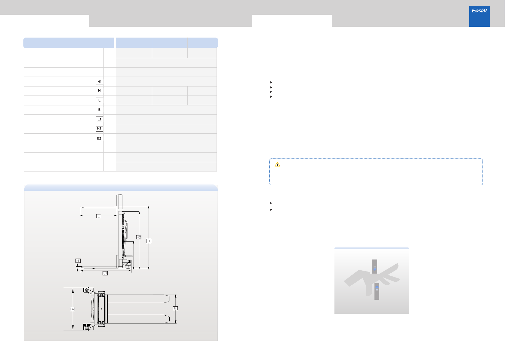
Figure1
Rated capacity
Load center
Dead-weight
Minimum fork height
Maximum fork height
Lowered Mast Height
Fork length
Overall fork width
Length of the stacker
Width of the stacker
Load-bearing wheel
Steering wheel
Minimum turning radius
1000
H10 H15
kg
mm
kg
mm
mm
mm
mm
mm
mm
mm
mm
kg
H20
1500 2000
600
270-320
85
1600/2500/3000
2030/1780/2030
1600
2030
1600
2030
1150
540/330-740
1670
764/834
Φ70×70
Φ180×50
1295
6. Operation protection
Hands and feet shall be kept far away from moving parts, such as frame, chains, forks and wheels to prevent
pinching hands.
5. Safety device and warning signs
Safety device, warning signs and the above safety precautions must be given enough attention to.
When handling the goods, the fork height must not exceed 300mm.
4. Hazardous area
The hazardous area usually refers to the area where the stacker or its lifting device (e.g. forks, attachments)
will pose threat to persons during their operation or lifting process. Typically, this range extends to the area
where goods or stacker accessories are lowered.
Unauthorized persons must leave the hazardous area. Whenever a situation causes possible harm to
persons, the operator must give a warning. If the unauthorized persons still stays in the hazardous
area after the waring is given, the operator must immediately stop the operation of the stacker.
Warning
3. Faults and defects
If stacker failure or defects occur, immediately notify the management personnel. If the stacker is not safe
for operation (such as wheel worn or brake failed, etc.), please stop using it before it is fully repaired.
2.
Free from rainwater or corrosion of harmful gases;
Room temperature of -20°C~+40°C;
Relative ambient humidity <90%;
Requirements for ground: hard, anti-skid and level without barriers.
The stacker is only applicable to indoor use and the application environment must meet the
following conditions:
1. Requirements for operator
The stacker must be operated by persons trained in operation. The operator shall be able to carry out
operation demonstration of moving and controlling goods for users, and he or she is responsible for the
stacker.Unauthorized persons are not allowed to operate the stacker. Do not carry or lift passengers.
Technical parameters
Model
Safe operating rules H10/15/20 Series Manual Pallet Stackers

03 04
Maintenance
7. Stable operation
Travel of stacker shall be stable, avoiding sharp turns and sudden start.
8. Loose or unstable stacking of goods or overloaded cargoes are prohibited.
Loose or unstable stacking of goods will cause falling of goods, or even turnover.
9. Other safety requirements
Do not use this stacker on the muddy ground.
Do not operate the stacker unless you have carefully checked its condition. Pay special attention
to the wheels, the handle assemblies, the frame, the chains, etc.
The operator shall wear safety shoes and gloves for protection.
Do not use the stacker in a potentially flammable and explosive atmosphere.
Do not use the stacker during strong wind forces.
Do not use the stacker on places insufficiently illuminated.
Do not use the stacker on a slopping ground.
The weight of goods should be distributed evenly on the two forks, do not use only one fork. The
center of gravity of goods beyond the two forks is forbidden.
Stackers should be parked on a smooth place, braked, with the forks lowered to the min. height.
Do not use the stacker with guarding removed.
Under special conditions or in special locations, the operator should be careful while operating
the stacker.
No modifications or alterations to the parts of the stacker, especially the safety device shall be made
without permission. All original spare parts have been checked by the quality inspection departments. To
ensure the safety and reliability of the stacker operation, only the manufacturer's spare parts can be used.
Replaced parts, such as batteries and waste oil must be disposed in accordance with the appropriate
environmental protection rules.
Only customer service persons specially trained by our company can carry out maintenance of the
stacker. Thoroughly standardized maintenance is the most important preconditions to ensure stable
and reliable operation performance of the stacker. Neglect of regular maintenance could result in failure
and malfunction of the stacker and poses a potential threat to the safety of the staff and operation.
Warning
1. Hydraulic oil
Please check the oil level every six months and change the oil every twelve months. 32 # hydraulic oil
is recommended, with total volume of about 2.0 liters.
2. Routine maintenance
It is necessary to check and maintain the stacker daily for sound application. Special attention should
be paid to:
(1)The wheels, the axles, as thread, rags, etc. may block the wheels and axles;
(2)The fork and the frame which may be deformed. The forks should be unloaded and lowered in the
lowest position.
3. Lubrication
Use motor oil or grease to lubricate all movable parts.
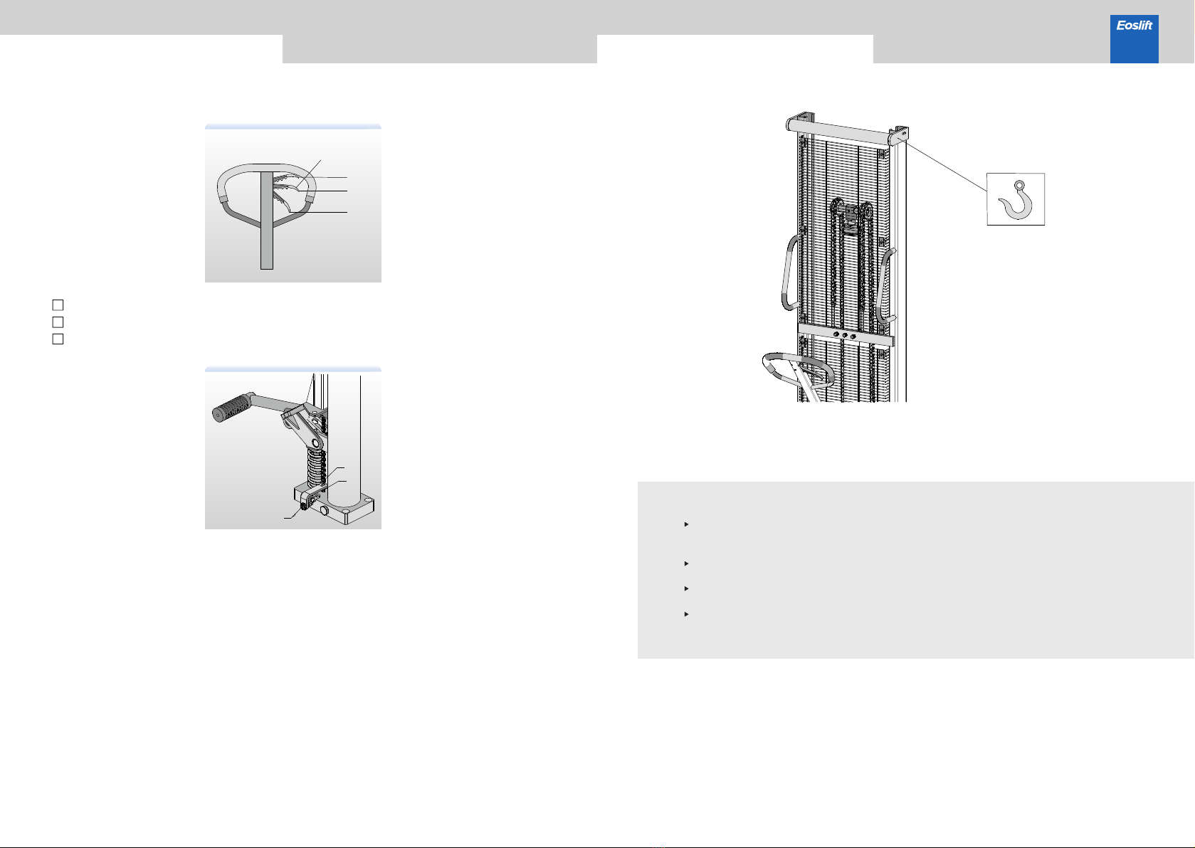
4. Remove the air
The air may enter the hydraulic pump during the transportation. It will cause the forks fails to be lifted
when switched to the lifting position. The air can be removed in the following way: pull the finger grip
control handle (3-1) to the lowering position and move handle up and down for several times.
Figure 2
Safe operating rules H10/15/20 Series Manual Pallet Stackers
Adjusting finger grip control handle
05 06
On the handle of this stacker, you can find finger grip control handle (3-1) which can be
regulated in three positions :
However if they have been changed, you can adjust them according to the following steps:
①If the forks elevate while pumping in the Middle position, turn the adjusting nut (4-2) on the
adjusting bolt (4-1) or screw (4-3) clockwise until pumping action does not raise or lower the forks
and the finger grip control handle (3-1) works properly Middle position.
②If the forks descend while pumping in the Middle position, turn the adjusting nut (4-2) on the
adjusting bolt (4-1) or screw (4-3) counterclockwise until pumping action does not raise or lower
the forks and the finger grip control handle(3-1) works properly Middle position .
③If the forks do not descend when the finger grip control handle (3-1) is in the Lowering position,
turn adjusting nut (4-2) on the adjusting bolt (4-1) or screw (4-3) clockwise until raising the control
handle lowers the forks. Then check the Middle position according to items ①and ② to make sure
the nut (4-2) and screw(4-3) are in the proper position.
④ If the forks do not elevate when the finger grip control handle (3-1) is in the Lifting position, turn
adjusting nut (4-2) on the adjusting bolt (4-1) or screw (4-3) counterclockwise until turning the
control handle to that position lifts the forks. Then check the function of the Lowering position and
Middle position according to items ①, ②and ③ is normal.
Transport, loading, test run and storage
Figure 3
Figure 5
Before loading, the operator shall check the stacker weight to choose the suitable
hoisting equipment. When the stacker is unloaded, the operator shall look out for
safety around to ensure safe landing of the stacker.
The truck shall be commissioned according to the following function tests: steering,
traveling, braking and combined functions with rated capacity.
When a stacker is inoperative, the loads (if applicable) shall be removed with proper
tools, the stacker shall be transported out of the working zone with a proper way.
Shut down and in storage for a long time, the storage environment shall be kept dry
and clean, with forks lowered to their lowest position.
As shown in Figure 5, lifting points are on both sides of the stacker.
Figure 4
3-1
Lowering
Middle position
Lifting
4-1
4-2
4-3
Lift - lifting
Middle position - travel
Lower - lowering
1
2
3
H10/15/20 Series Manual Pallet Stackers

Troubleshooting
07 08
This chapter enables the user to identify and rectifies basic faults and the effects of incorrect
operation. When trying to locate a fault, proceed in the order shown in the table below. If, after
carrying out the following remedial action listed in“actions”, the stacker cannot be restored to
operation, contact the manufacturer’s after-sale service department. Additional troubleshooting
must only be performed by the manufacturer’s specialist service engineers. The manufacturer's
customer service department is specially trained to carry out these operations.
1
2
3
4
5
The forks
descended without
operation
Note: Do not attempt to repair the stacker unless you are trained in the professions.
Impurities in the oil cause
the valve to be unable to
close tightly
Seals damaged
Adjusting nut(4-2) or
adjusting screw(4-3) in
wrong positions
Change hydraulic oil
Replace the damaged
seals with new seals
Adjust nut(4-2) or adjusting
screw(4-3)
Fault Possible cause Action
No.
The forks cannot
be lifted to max.
height
The forks cannot
be lifted
The forks cannot
be lowered
Oil leakage
The hydraulic oil is
insufficient
The hydraulic oil is
insufficient
The hydraulic oil has
impurities
Adjusting nut(4-2) or
adjusting screw(4-3) in
wrong positions
Air enters into the cylinder
Seals damaged
The piston rod or the frame
is deformed resulting from
overloading or cargo
slanting to one side
The forks was kept in raised
position for extended period
of time, then the piston rod
is exposed to the air and gets
rusted , which blocks the
motion of the piston
Adjusting nut(4-2) or
adjusting screw(4-3) in wrong
positions
Rollers rusted and blocked
Seals damaged
Parts damaged
Replace the damaged seals
with new seals
Replace the damaged parts
with new parts
Add the hydraulic oil
Add the hydraulic oil
Change hydraulic oil
Adjust nut(4-2) or adjusting
screw(4-3)
Put the finger grip handle in
the upper position and press
the handle dozens of times
Replace the damaged seals
with new seals
Replace the related parts of
the cylinder or the frame with
new ones
Keep the forks at the lowest
position while not in use, and
keep piston rods lubricated in
time
Adjust nut(4-2) or adjusting
screw(4-3)
Lubricate rollers
H10/15/20 Series Manual Pallet Stackers
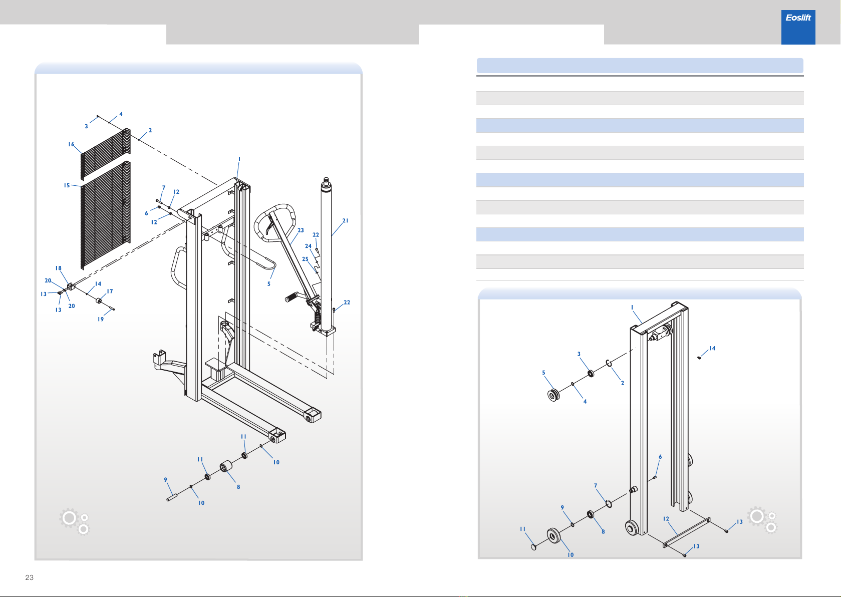
09 10
H10/15/20 Series Manual Pallet Stackers
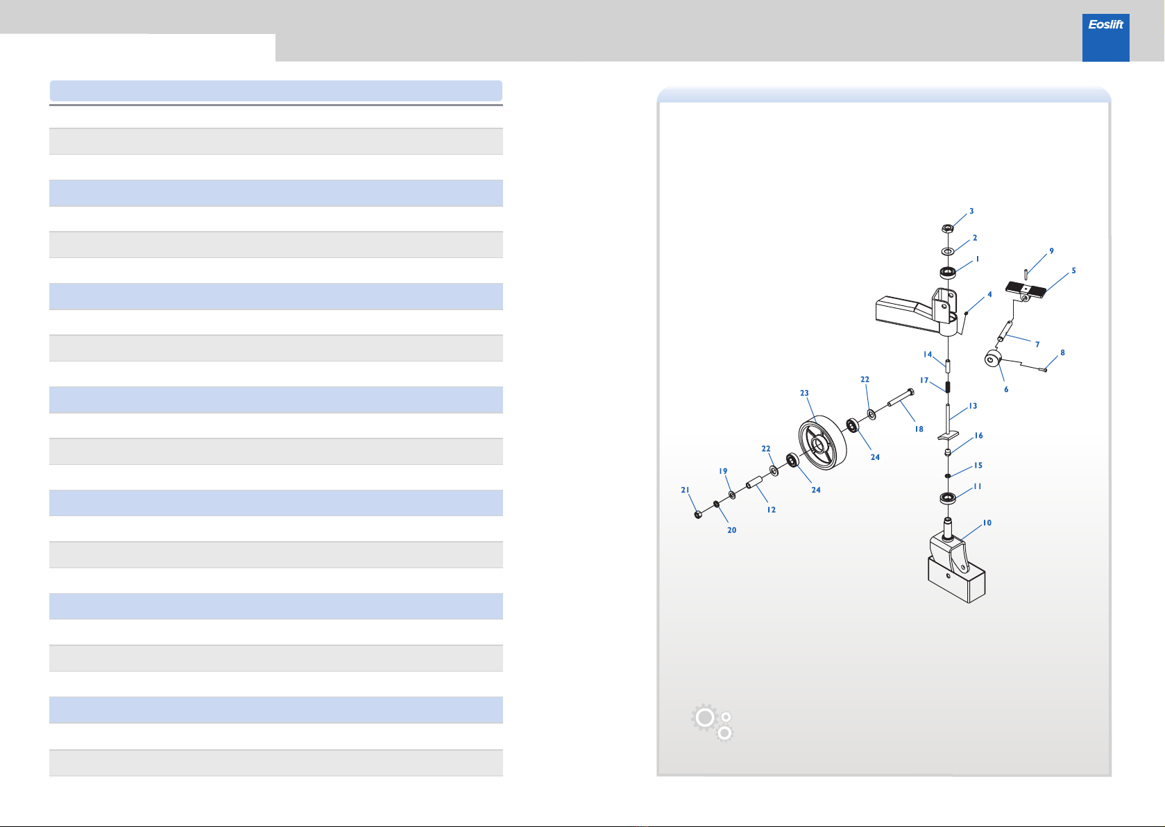
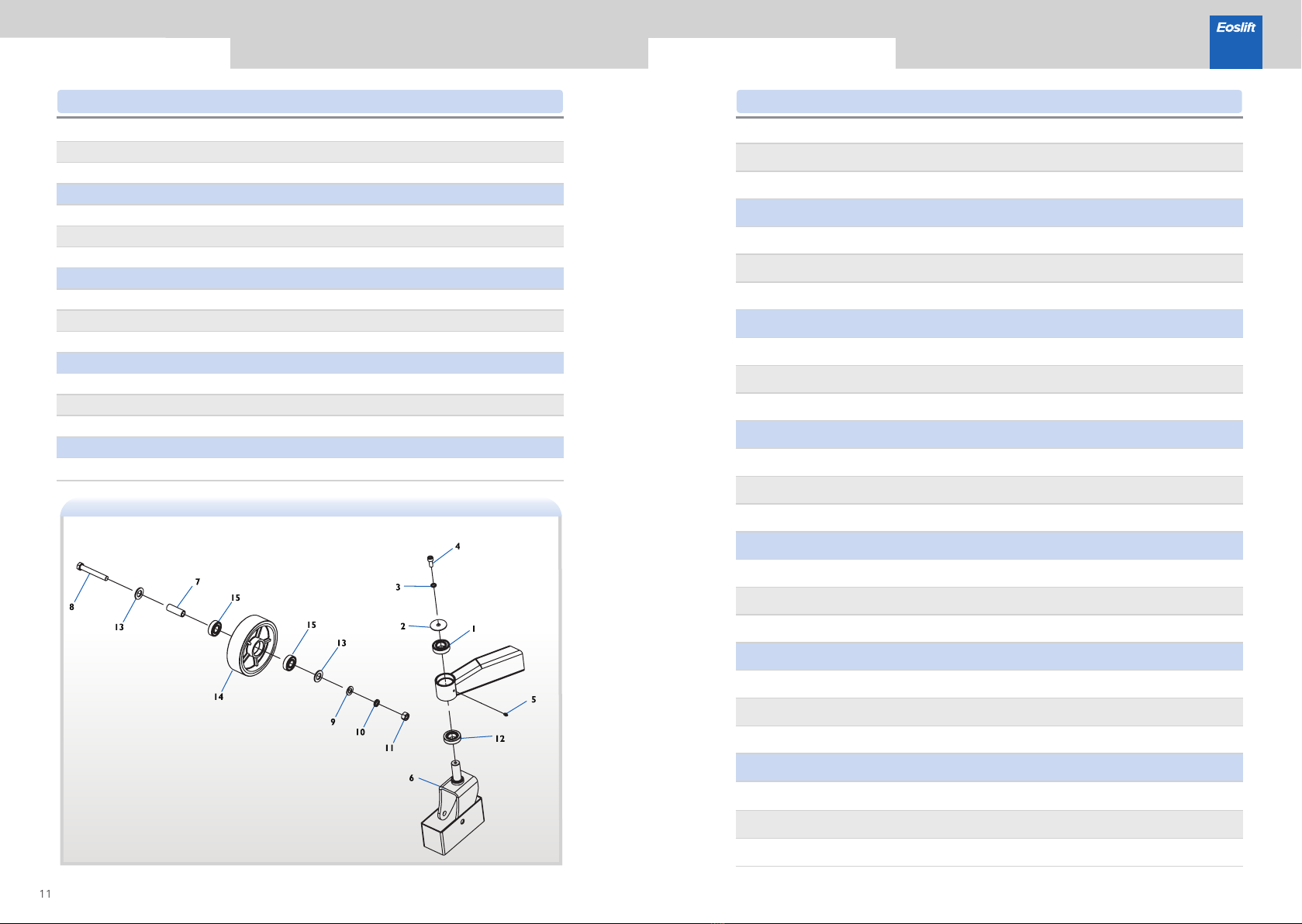
1
2
3
4
5
6
7
8
9
10
11
12
13
14
15
16
17
18
19
20
21
22
23
24
WC02000224
WC02000343
WE04000019
WC02000019
WC02000345
WC02000346
WC02000347
WE03000021
WE06000012
WC02000350
WC02000225
WC02000348
WC02000351
WC02000342
WE04000020
WC02000344
WC02000349
WE01000004
WE05000012
WE05000013
WE04000012
WE05000014
WC02000226
WC02000285
WC02000435
WC02000022
Washer
Pedal, galvanized
Clamping roller, galvanized
Shaft, galvanized
GB117, Taper pin 6 × 42, galvanized
Ribbon brake guide wheel bracket,black
GB297,Tapered Roller Bearings 30205
Big wheel shaft sleeve
Brake rod, black
Sleeve
Connecting sleeve, galvanized
Reset spring
GB95,Plain washer 14,galvanized
GB6170, Hexagon nut M14, galvanized
GB95,Plain washer 20,galvanized
Nylon wheelφ180×50(plane wheel)
1
1
1
1
1
1
1
1
1
1
1
1
1
1
1
1
1
1
1
1
1
2
1
2
GB276,Deep groove ball bearing 6205,
two-side shielded
GB6173,Hexagon thin nut M22×1.5,
galvanized
GB70.1, Hexagon socket head cap screw
M6 × 20, galvanized
JB7940.4, Push-fit type grease nipple 6
GB6172.1,Hexagon thin nut M10,galvanized
GB5780,Hexagon head bolt M14×100,
galvanized
GB93,Normal type spring lock washer 14,
galvanized
Iron-core PU wheel φ180×50, bright red PU,
black iron core
Nylon wheelφ180×50(flower-shape wheel)
GB276,Deep groove ball bearing 6204,
two-side shielded
Qty.
NO. Parts number Description
Parts list· Guide wheel,with brake
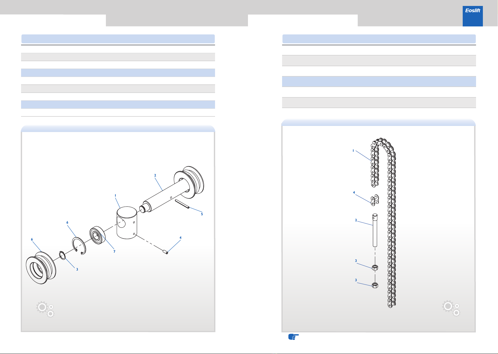
11 12
H10/15/20 Series Manual Pallet Stackers
1
2
3
4
5
6
7
8
9
10
11
12
13
14
15
WC02000224
WC02000352
WE05000002
WE03000004
WC02000019
WC02000353
WC02000348
WE01000004
WE05000012
WE05000013
WE04000012
WC02000225
WE05000014
WC02000226
WC02000285
WC02000435
WC02000022
Wheel shaft cover, galvanized
JB7940.4, Push-fit type grease nipple 6
Rear wheel carrier, black
Big wheel shaft sleeve
GB95,Plain washer 14,galvanized
GB6170, Hexagon nut M14, galvanized
GB297,Tapered Roller Bearings 30205
GB95,Plain washer 20,galvanized
Nylon wheelφ180×50(plane wheel)
1
1
1
1
1
1
1
1
1
1
1
1
2
1
2
GB276,Deep groove ball bearing 6205,
two-side shielded
GB93,Normal type spring lock washer 10,
galvanized
GB70.1,Hexagon socket head cap screw
M10×25,galvanized
GB5780,Hexagon head bolt M14×100,
galvanized
GB93,Normal type spring lock washer 14,
galvanized
Iron-core PU wheel φ180×50, bright red PU,
black iron core
GB276,Deep groove ball bearing 6204,
two-side shielded
Nylon wheelφ180×50(flower-shape wheel)
1
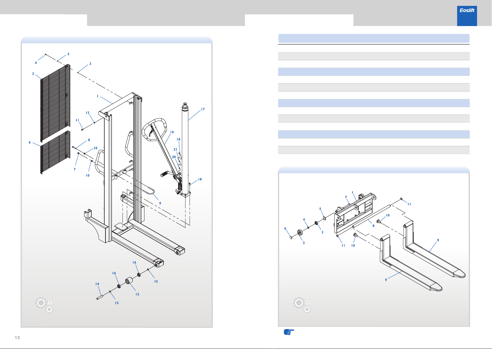
2
3
4
5
6
7
8
9
10
11
12
13
14
15
16
17
18
19
20
21
WC02000337
WC02000402
WC02000421
WC02000424
WC02000433
WC02000357
WE04000005
WE03000016
WE05000004
WC02000330
WE04000013
WE01000002
WC02000355
WE04000009
WE03000014
WE04000015
WC02000227
WC02000286
WC02000259
WE07000004
WC02000022
WC01000020
WC01000025
WE03000004
WC02000338
WE05000009
WE05000002
External frame (1.0t, fixed), 5012
External frame (1.0t, movable), 5012
External frame (1.5t, fixed), 5012
External frame (1.5t, movable), 5012
External frame (2.0t, movable), 5012
Guarding screen, black
GB6170,Hexagon nut M5,galvanized
GB95,Plain washer 5,galvanized
Guarding screen, black
Locking ring, galvanized
GB6170,Hexagon nut M10,galvanized
Nylon wheel φ70×70
Front wheel shaft
GB894.1,Circlip for shaft 20,blackening
Cylinder assembly(1.0t/1.5t,1.6), black
Cylinder assembly(2.0t,1.6), black
EOS-HS handle
GB95,Plain washer 10,galvanized
1
1
10
10
10
1
2
1
1
3
4
4
2
2
4
4
1
5
1
3
3
Gb5781, Hexagon head bolts-Full thread
M10 × 50, galvanized
GB802,Acorn nut--sssembling typeM10,
galvanized
GB70.1,Hexagon socket head cap screw
M5×16,galvanized
GB889.1, Hexagon locking nut M8, galvanized
GB276,Deep groove ball bearing 6204,
two-side shielded
GB70.1,Hexagon socket head cap screw
M10×25,galvanized
GB93,Normal type spring lock washer 10,
galvanized
GB70.1,Hexagon socket head cap screw
M8×20,galvanized
Iron-core PU wheel φ70×70, bright red PU
Qty.
NO. Parts number Description Qty.
NO. Parts number Description
Parts list· Guide wheel Parts list· Single frame
13 14
H10/15/20 Series Manual Pallet Stackers
1
2
3
4
5
6
7
8
9
10
11
WC02000403
WC02000425
WC02000434
WC02000341
WC02000231
WC02000224
WE07000010
WE07000007
WC02000232
WE03000019
WC02000404
WC02000282
WC02000284
WE07000011
Fork guide plate bracket(1.0t), black
Fork guide plate bracket(1.5t), black
Fork guide plate bracket(2.0t), black
Iron wheel (1.0t/1.5t)
Iron wheel (2.0t)
GB894.1,Circlip for shaft 25,blackening
GB893.1,Circlip for hole 52,blackening
Iron wheel cap
Shaft (740) galvanized
Fork assembly (1150), black
Adjusting screw,galvanized
GB894.1,Circlip for shaft 32,blackening
1
4
4
4
4
4
8
1
2
2
2
GB276,Deep groove ball bearing 6205,
two-side shielded
Gb77, Hexagon socket set screw with flat point
M12×20,galvanized
Qty.
NO. Parts number Description
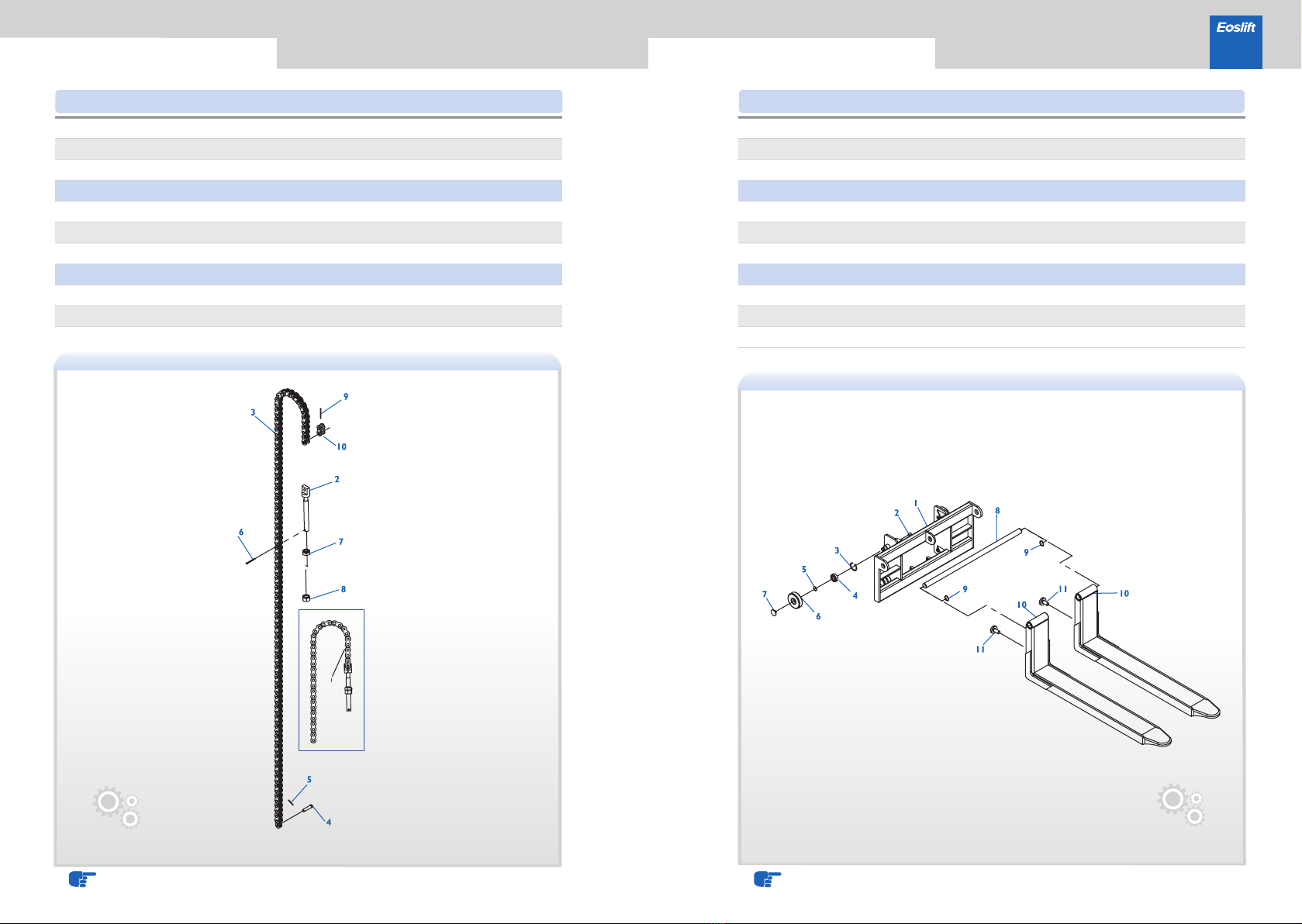
Parts list· Single frame Parts list· Movable fork assy
NOTE:For single mast models
15 16
H10/15/20 Series Manual Pallet Stackers
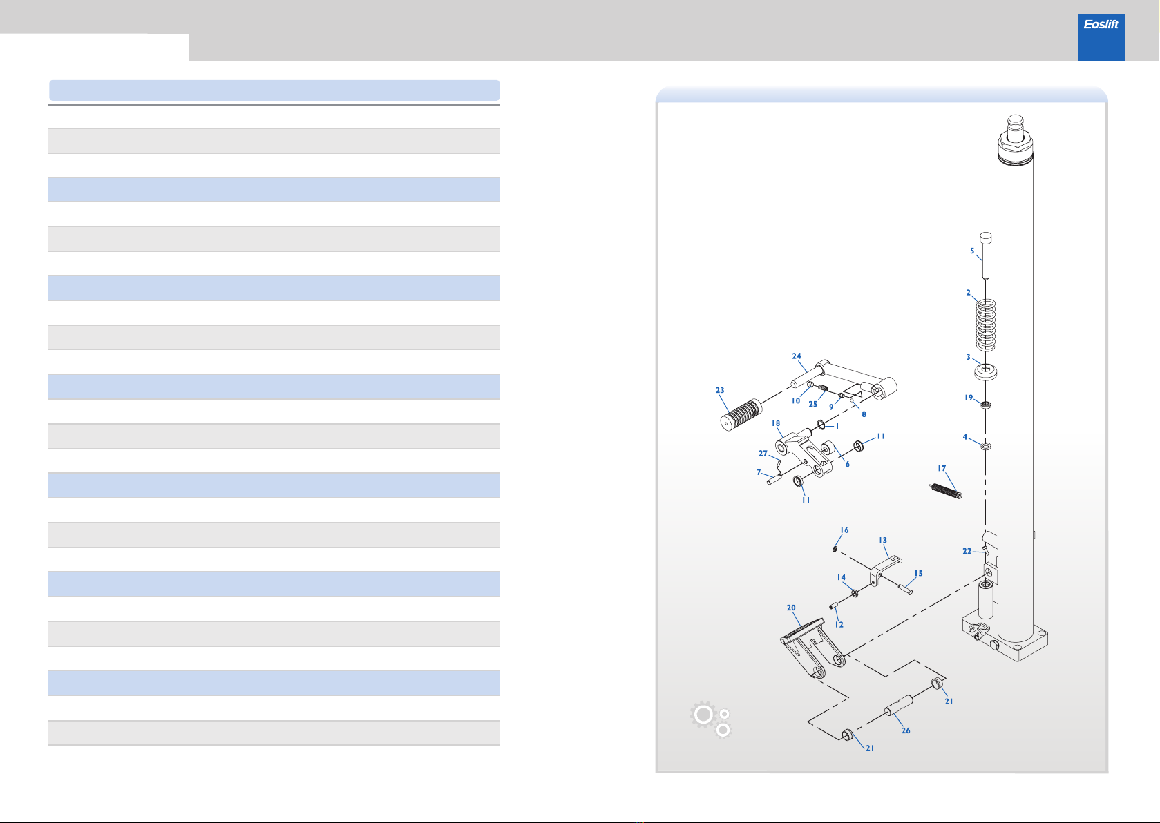
1
2
3
4
5
6
7
8
9
10
11
12
13
14
15
16
17
18
19
20
21
22
23
24
25
26
27
WE07000004
WC02000365
WC02000108
WC02000387
WC02000363
WC02000390
WC02000391
WC02000069
WC02000393
WC02000375
WC02000401
WE03000003
WC02000377
WE04000003
WC02000378
WE07000012
WC02000397
WC02000395
WC02000388
WC02000399
WC02000400
WE03000016
WC02000394
WC02000396
WC02000392
WC02000398
WE06000016
GB894.1,Circlip for shaft 20,blackening
Pressure spring
Spring cover,galvanized
Seal ring UHS14
Pump core
Small roller, galvanized
Roller shaft, galvanized
GB308,Steel ball S7
Spring seat
Screw
Flanged sliding bearing 30/23×20×8
Unloading plate, black
GB6172.1, Hexagon thin nut M8, galvanized
Pin, galvanized
GB894.1,Circlip for shaft 8,blackening
Extension spring
Pedal stand, black
Dustproof ring DH14
Handle holder, black
Flanged sliding bearing 30/23×20×11.5
Rubber sleeve
Pedal, black
Spring
Pivot, galvanized
GB117, Taper pin 4 × 18, blackening
1
1
1
1
1
1
1
1
1
1
2
1
1
1
1
1
1
1
1
1
2
1
1
1
1
1
1
Gb73, Slotted set screws with flat point
M8 × 20, galvanized
GB70.1,Hexagon socket head cap screw
M5×16,galvanized
Qty.
NO. Parts number Description
Parts list· Pedal
17 18
H10/15/20 Series Manual Pallet Stackers
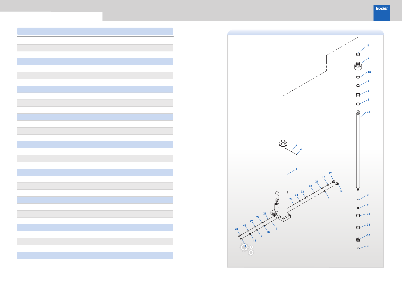
1
2
3
4
5
6
7
8
9
10
11
12
13
14
15
16
17
18
19
20
21
22
23
24
25
26
27
28
29
30
31
32
33
WC02000358
WC02000382
WE07000004
WE03000023
WC02000383
WC02000364
WC02000385
WC02000384
WC02000362
WC02000386
WC02000110
WC02000369
WC02000115
WC02000381
WC02000389
WC02000376
WC02000045
WC02000374
WC02000375
WC02000372
WC02000370
WC02000371
WC02000132
WC02000373
WC02000069
WC02000366
WC02000368
WC02000367
WC02000117
WC02000361
WC02000360
WC02000380
WC02000379
Cylinder body(1.0t/1.5t,1.6m),black
GB3452.1,O-ring φ15×2.65
GB894.1,Circlip for shaft 20,blackening
GB982, Combination sealing gasket 6
Guide sleeve
GB3452.1,O-ring φ31.5×2.65
GB3452.1,O-ringφ34.5×2.65
Cap, galvanized
GB3452.1,O-ring φ31.5×3.55
Dustproof ring DHS31.5
Left screw plug
GB3452.1,O-ring φ16×1.8
Flow-limiting valve assembly
GB982, Combination sealing gasket 12
Screw plug, galvanized
Safety valve spool
Adjusting spring
Screw
Spool
Spool spring
Valve sleeve
GB3452.1,O-ring φ9.0×1.8
Sealing gasket
GB308,Steel ball S7
Dust cover
Unloading spring
Unloading rod
GB3452.1,O-ring φ6.9×1.8
Piston
Piston rod (1.0t / 1.5t, 1.6m)
Piston guide ring ZS35
Sealing ring YXD35
1
2
1
1
1
1
1
1
1
1
1
2
2
1
1
1
1
1
1
1
1
1
1
1
1
1
1
1
2
1
1
1
1
GB818,Pan head screw with cross recess
M6×10,galvanized
Qty.
NO. Parts number Description
Parts list· Cylinder assembly(φ31.5)

19 20
H10/15/20 Series Manual Pallet Stackers
1
2
3
4
5
6
7
8
9
10
11
12
13
14
15
16
17
18
19
20
21
22
23
WC02000437
WC02000414
WC02000418
WC02000369
WC02000389
WC02000376
WC02000045
WC02000374
WC02000375
WC02000372
WC02000370
WC02000371
WC02000373
WC02000069
WC02000366
WC02000368
WC02000367
WC02000438
WC02000410
WC02000419
WC02000382
WC02000411
WC02000407
WE05000014
WC02000413
WC02000409
WC02000384
Cylinder (2.0t,1.6m),black
Cylinder (2.5m), black
Cylinder (3.0m), black
Left screw plug
GB982, Combination sealing gasket 12
Screw plug, galvanized
Safety valve spool
Adjusting spring
Screw
Spool
Spool spring
Valve sleeve
Sealing gasket
GB308,Steel ball S7
Dust cover
Unloading spring
Unloading rod
Piston rod (2.0t, 1.6m)
Piston rod(2.5m)
Piston rod(3.0m)
GB3452.1,O-ring φ15×2.65
Piston
QYD seal ring 40 × 32 × 8
GB95,Plain washer 20,galvanized
Guide sleeve
GB3452.1,O-ring φ39.5×2.65
GB3452.1,O-ringφ34.5×2.65
1
2
1
1
1
1
1
1
1
1
1
1
1
1
1
1
2
1
1
1
1
1
1
24
25
26
27
28
29
30
31
32
33
WC02000412
WC02000058
WC02000408
WC02000383
WE03000023
WC02000117
WC02000132
WC02000115
WE07000004
WC02000381
Cap, galvanized
Dustproof ring DH35
Piston guide ring ZS40
GB982, Combination sealing gasket 6
GB3452.1,O-ring φ6.9×1.8
GB3452.1,O-ring φ9.0×1.8
GB3452.1,O-ring φ16×1.8
GB894.1,Circlip for shaft 20,blackening
Flow-limiting valve assembly
1
1
1
1
1
2
1
2
1
1
GB818,Pan head screw with cross recess
M6×10,galvanized
Qty.
NO. Parts number Description Qty.
NO. Parts number Description
Parts list· Cylinder assembly(φ35)

21 22
H10/15/20 Series Manual Pallet Stackers
1
2
3
4
5
6
7
8
9
10
11
12
13
14
15
16
17
18
19
20
21
22
23
24
25
WC02000405
WC02000420
WE04000005
WE03000016
WE05000004
WC02000355
WE04000013
WE01000002
WC02000227
WC02000286
WC02000259
WE07000004
WC02000022
WE04000009
WE03000014
WE07000008
WC02000406
WC02000357
WC02000292
WC02000293
WC02000294
WC02000295
WE05000005
WC01000022
WC01000023
WE03000004
WC02000338
WE05000002
WE05000009
External frame (1.0t, 2.5m, fixed), 5012
External frame(1.0t,3.0m,movable),5012
GB6170,Hexagon nut M5,galvanized
GB95,Plain washer 5,galvanized
Locking ring, galvanized
Iron-core PU wheel φ70×70, bright red PU
Nylon wheel φ70×70
Front wheel shaft
GB894.1,Circlip for shaft 20,blackening
GB6170,Hexagon nut M10,galvanized
GB894.1,Circlip for shaft 10,blackening
Guarding screen (2.5m), black
Guarding screen (3.0m), black
Guarding screen, black
Upper guide wheel
Upper guide bracket, galvanized
Pivot
Cylinder assembly (2.5m), black
Cylinder assembly (3.0m), black
EOS-HS handle
GB95,Plain washer 10,galvanized
1
10
10
10
1
2
1
2
2
4
4
3
4
2
1
1
2
2
2
2
1
5
1
3
3
GB70.1,Hexagon socket head cap screw
M5×16,galvanized
GB802,Acorn nut--sssembling type
M10,galvanized
Gb5781, Hexagon head bolts-Full thread
M10 × 50, galvanized
GB276,Deep groove ball bearing 6204,
two-side shielded
GB70.1,Hexagon socket head cap screw
M8×20,galvanized
GB93,Normal type spring lock washer 8,
galvanized
GB70.1,Hexagon socket head cap screw
M10×25,galvanized
GB93,Normal type spring lock washer 10,
galvanized
Qty.
NO. Parts number Description
Parts list· Cylinder assembly(φ35)Parts list· External frame
23 24
H10/15/20 Series Manual Pallet Stackers
1
2
3
4
5
6
7
8
9
10
11
12
13
14
WC02000290
WC02000299
WE07000006
WC02000022
WE07000004
WC02000261
WE03000019
WE07000007
WC02000224
WE07000010
WC02000231
WC02000232
WD01000211
WE03000020
WE03000017
Internal frame, 5012 (2.5m)
Internal frame, 5012 (3.0m)
GB893.1,Circlip for hole 47,blackening
GB894.1,Circlip for shaft 20,blackening
Sprocket (roller chain)
GB893.1,Circlip for hole 52,blackening
GB894.1,Circlip for shaft 25,blackening
Iron wheel
Iron wheel cap
Lower stay bar
1
2
2
2
2
8
4
4
4
4
4
1
2
1
GB276,Deep groove ball bearing 6204,
two-side shielded
Gb77, Hexagon socket set screw with flat point
M12×20,galvanized
GB276,Deep groove ball bearing 6205,
two-side shielded
GB70.1,Hexagon socket head cap screw
M10×12,galvanized
GB70.1,Hexagon socket head cap screw
M8×12,galvanized
Qty.
NO. Parts number Description
Parts list· Internal frameParts list· External frame
H10/15/20 Series Manual Pallet Stackers
26
1
2
3
4
5
6
7
8
WC02000354
WC02000356
WE07000004
WE03000022
WE06000013
WC02000261
WC02000317
WC02000022
WE07000006
Top beam seat,galvanized
Top beam shaft, galvanized
GB894.1,Circlip for shaft 20,blackening
Sprocket (roller chain)
Sprocket (leaf chain)
GB893.1,Circlip for hole 47,blackening
1
1
2
1
1
2
2
2
1
2
3
4
WC02000340
WC02000287
WC02000300
WC02000260
WE04000012
WC02000222
Roller chain(1.6m)
Roller chain(2.5m)
Roller chain(3.0m)
Bolt
GB6170, Hexagon nut M14, galvanized
Single-row roller chain CL connector 12A-1
2
2
4
4
GB71,Slotted set screws with flat point
M6×16,galvanized
GB879.1,Spring type straight pin
5×50,blackening
GB276,Deep groove ball bearing 6204,
two-side shielded
25
Qty.
NO. Parts number Description Qty.
NO. Parts number Description
Parts list· Roller ChainParts list· Top beam assembly
NOTE:For the 1.0t models.
H10/15/20 Series Manual Pallet Stackers
1
2
3
4
5
6
7
8
9
10
WC02000423
WJ11900006
WJ11900007
WJ11900015
WJ11900003
WJ11900001
WJ11900005
WJ11900004
WJ11900002
WJ11900016
Leaf chain, 58 links (1.6m)
LH1223 long end connector
Leaf chain
Chain pivot
GB91, Cotter pin 2 × 16
GB91, Cotter pin 3.2 × 32
Spherical nut
GB6171, nut M14 × 1.5 × 12.8
GB91, Cotter pin 2 × 32
Chain shackle
2
2
2
2
2
2
2
2
2
2
27 28
WC02000416
WE03000019
WE07000007
WC02000224
WE07000010
WC02000231
WC02000232
WC02000404
WE07000011
WC02000282
WC02000284
Fork guide plate bracket(1.0t), black
GB893.1,Circlip for hole 52,blackening
GB894.1,Circlip for shaft 25,blackening
Iron wheel
Iron wheel cap
Shaft (740) galvanized
GB894.1,Circlip for shaft 32,blackening
Fork assembly (1150), black
Adjusting screw,galvanized
1
8
4
4
4
4
4
1
2
2
2
1
2
3
4
5
6
7
8
9
10
11
GB276,Deep groove ball bearing 6205,
two-side shielded
Gb77, Hexagon socket set screw with flat point
M12×20,galvanized
Qty.
NO. Parts number Description Qty.
NO. Parts number Description
Parts list· Movable fork assyParts list· Leaf chain
NOTE:For double mast modelsNOTE:For the 1.5t and 2.0t models
H10/15/20 Series Manual Pallet Stackers
1
2
3
4
5
6
7
8
9
10
11
12
13
14
15
16
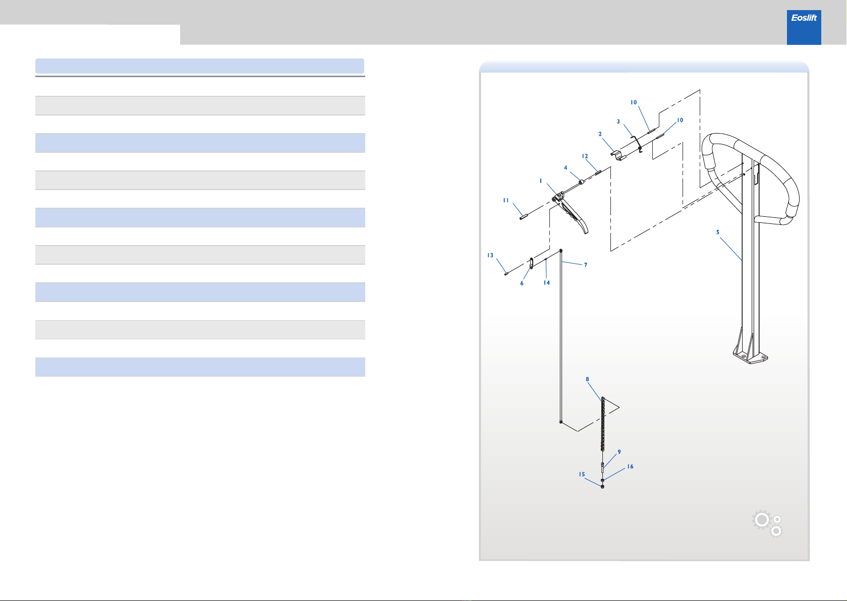
WJ10800036
WJ10800037
WJ10800038
WJ10800039
WJ10800040
WJ10800041
WJ10800042
WJ10800043
WJ10800044
WJ10800045
WJ10800046
WJ10800047
WJ10800048
WJ10800049
WJ10800050
WJ10800051
Finger grip handle
positioning plate
torsion spring
plastic roller
handle welded
Connecting sheet of pull rod
pull rod
chain
adjusting bolt
Spring type pin(10)
Spring type pin(11)
Spring type pin(12)
Spring type pin(13)
Spring type pin(14)
nut(16)
locking nut(15)
1
1
1
1
1
1
1
1
1
2
1
1
1
1
1
1
29 30
Qty.
NO. Parts number Description
Parts list· Handle assemblies
H10/15/20 Series Manual Pallet Stackers
31 32
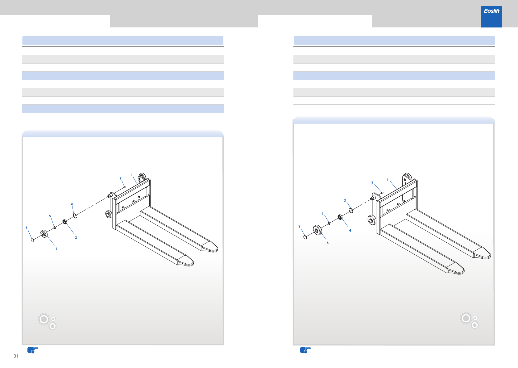
1
2
3
4
5
6
7
WC02000339
WC02000422
WC02000341
WC02000224
WE07000007
WE07000010
WC02000232
WE03000019
Fixed fork (1.0t), black
Fixed fork (1.5t), black
Iron wheel
GB893.1,Circlip for hole 52,blackening
GB894.1,Circlip for shaft 25,blackening
Iron wheel cap
1
4
4
4
4
4
8
GB276,Deep groove ball bearing 6205,
two-side shielded
GB77, Hexagon socket set screw with flat point
M12×20,galvanized
1
2
3
4
5
6
7
WC02000289
WE03000019
WE07000007
WC02000224
WE07000010
WC02000231
WC02000232
Fixed fork, black (1.0t)
GB893.1,Circlip for hole 52,blackening
GB894.1,Circlip for shaft 25,blackening
Iron wheel
Iron wheel cap
1
8
4
4
4
4
4
GB276,Deep groove ball bearing 6205,
two-side shielded
Gb77, Hexagon socket set screw with flat point
M12×20,galvanized
Qty.
NO. Parts number Description Qty.
NO. Parts number Description
Parts list· Fixed fork assyParts list· Fixed fork assy
NOTE:For double mast modelsNOTE:For single mast models
This manual suits for next models
2
Table of contents
Other Eoslift Truck manuals


 Operator's manual")


