ep ES10-10WA User manual

1

1

1
Foreword
The present original operating instructions are designed to provide sufficient instruction
for the safe operation and maintenance of the truck. Please be sure to read this operator
manual carefully if you are operator or are in charge of the truck,before you operate and
service the truck. Only in this way can you protect yourself and make the truck play a role as
much as possible.
Our trucks are subject to ongoing development, so maybe there are some differences
between your product and the description in this manual. And the operator manual details will
be different because of customer's special requirements.
If you have any questions ,please keep in touch with the sales department or let the
dealer know.
Notes:
1. This manual is used for operation and maintenance , the detail parameters, size
and specifications in context is only for reference , the real parameters will depend on
sale files.
2. Manual pictures for reference only, the real car shall prevail, and shall not affect the
manual use.
3.Manual pictures only sign for one of the models in this series models.

2
Catalog
Correct use and application..............................................................................................................1
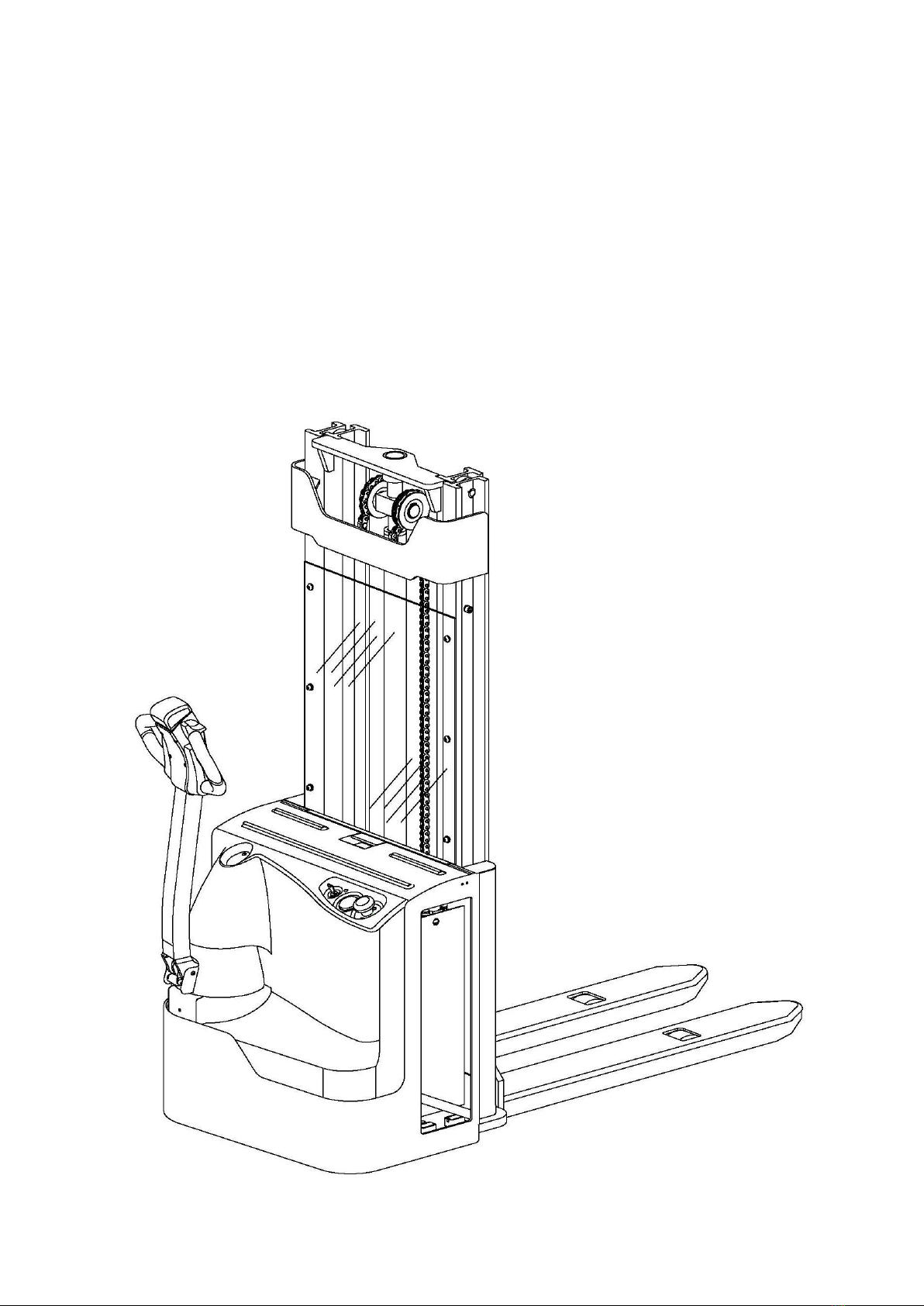
Chapter 1 stacker Description.......................................................................................................2
1 Application....................................................................................................................................2
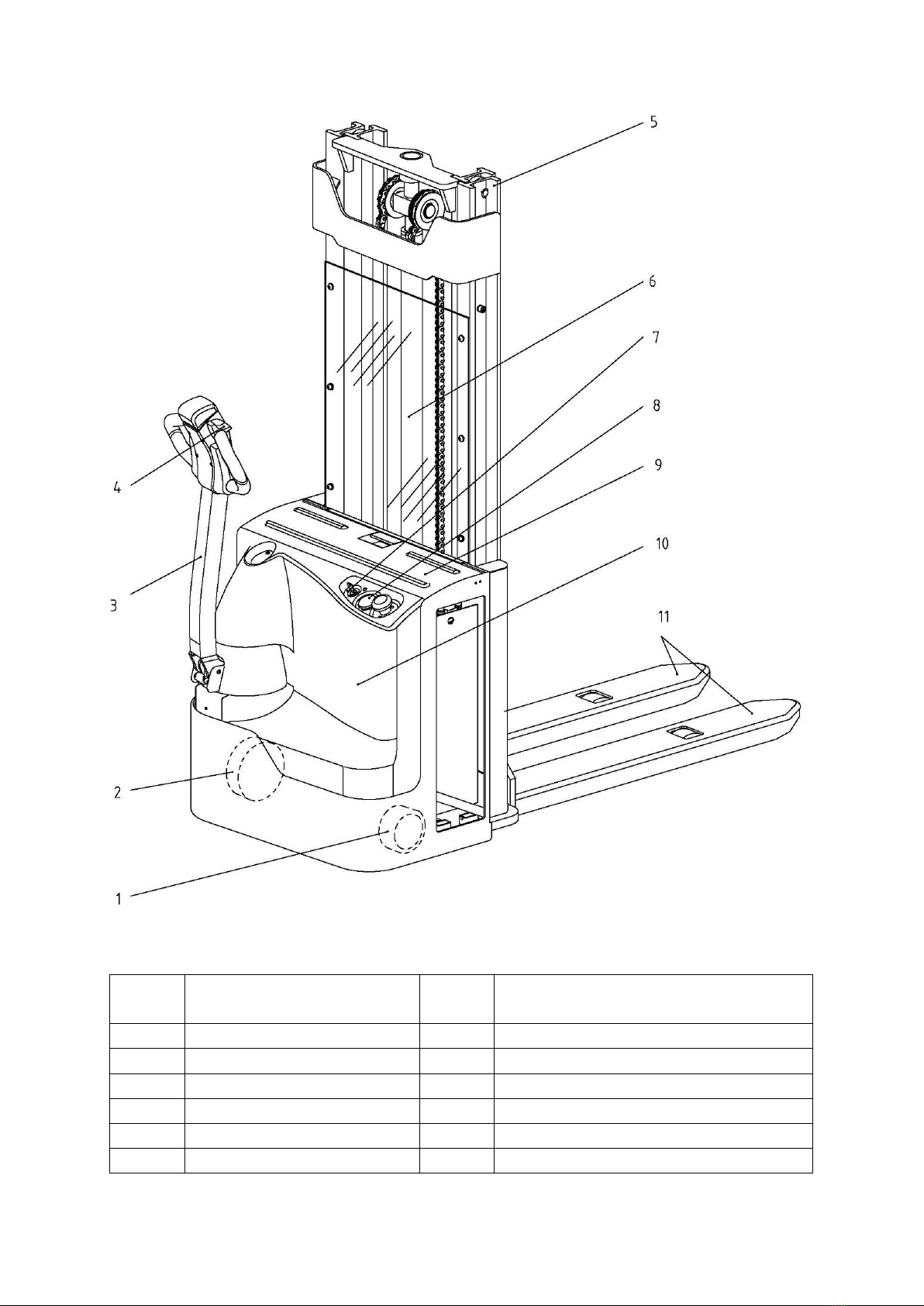
2 Assemblies...................................................................................................................................3
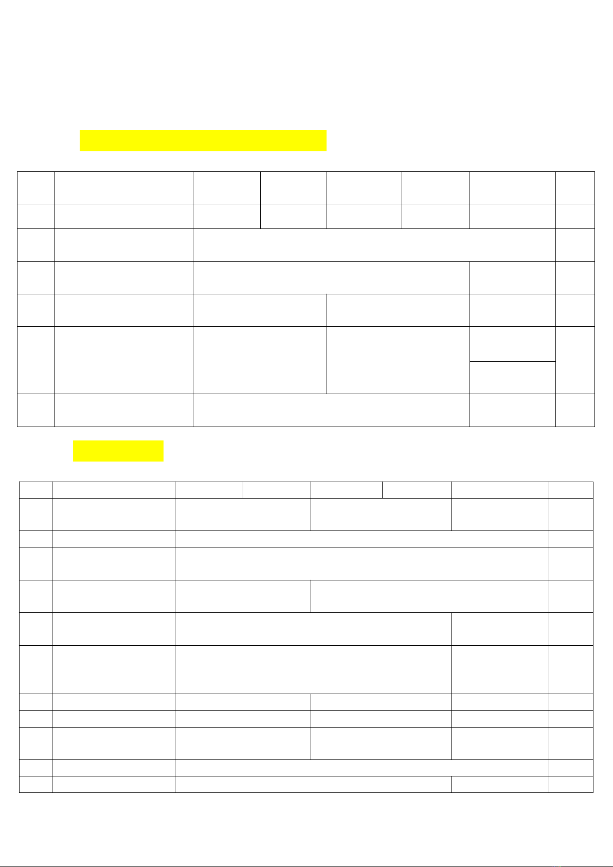
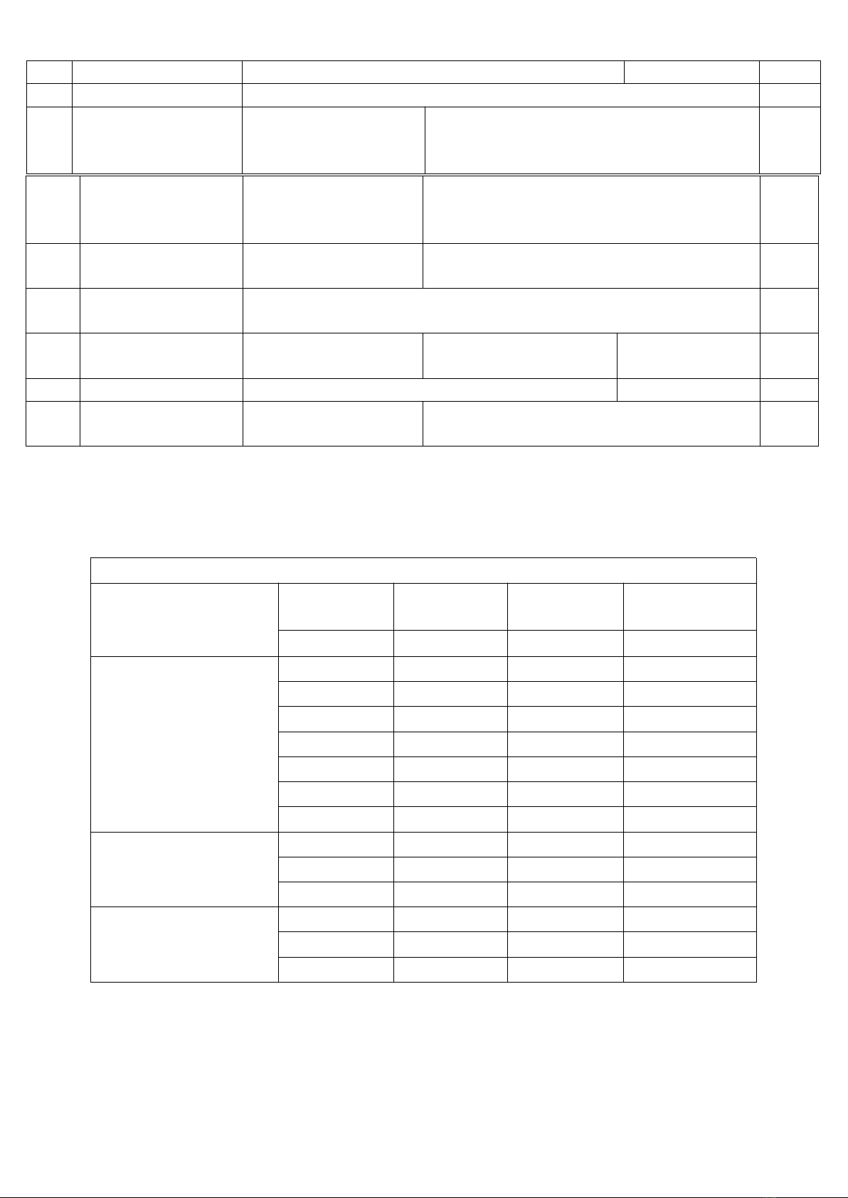
3 Standard Version Specifications...............................................................................................4
3.1 Performance data for standard stackers........................................................................4
3.2 Dimensions......................................................................................................................... 4
3.3 Conditions of use............................................................................................................... 8
4. Identification points and data plates....................................................................................... 8
4.1 stacker data plate............................................................................................................ 10
4.2 Capacity chart.................................................................................................................. 10
Chapter 2 Operation.......................................................................................................................11
1 Safety Regulations for the Operation of stacker..................................................................11
2 Controls and Displays.............................................................................................................. 12
3 Starting up the stacker............................................................................................................. 14
4 Industrial stacker operation..................................................................................................... 14
4.1 Safety regulations for stacker operation...................................................................... 14
4.2 Travelling, Steering, Braking......................................................................................... 15
4.3 Collecting and depositing loads.................................................................................... 17
5 Parking the stacker securely...................................................................................................18
6 Display instrument.................................................................................................................... 18
6.1 Battery Discharge Indicator........................................................................................... 18
6.2 Operating hours display................................................................................................. 18
6.3 Power up test................................................................................................................... 19
7 Troubleshooting........................................................................................................................ 19
Chapter 3 Battery Maintenance, Charging & Replacement.................................................20
1 Safety regulations for handling acid batteries...................................................................... 20
2 Battery specifications............................................................................................................... 20
3 Exposing the battery.................................................................................................................21
4 Charging the battery.................................................................................................................21
5 Battery removal and installation............................................................................................. 22
Chapter 4 stacker Maintenance.................................................................................................. 24
1 Operational safety and environmental protection................................................................24
2 Maintenance Safety Regulations........................................................................................... 24
3 Servicing and inspection..........................................................................................................25
4 Maintenance Checklist.............................................................................................................26
5 Lubrication Schedule................................................................................................................28
5.1 Fuels, coolants and lubricants.......................................................................................29
6 Maintenance Instructions.........................................................................................................30
6.1 Prepare the stacker for maintenance and repairs......................................................30

3
6.2 Removing the front panel............................................................................................... 30
6.3 Remove the drive panel................................................................................................. 30
6.4 Replacing the drive wheel..............................................................................................31
6.5 Checking the hydraulic oil level.....................................................................................31
6.6 Check transmission oil level.......................................................................................... 31
6.7 Flushing the gauze filter, Replacing the gauze filter..................................................32
6.8 Checking electrical fuses............................................................................................... 33
6.9 Recommissioning............................................................................................................ 34
7 Decommissioning the industrial stacker................................................................................34
7.1 Prior to decommissioning...............................................................................................34
7.2 During decommissioning................................................................................................34
7.3 Restoring the stacker to operation after decommissioning.......................................35
8 Safety checks to be performed at regular intervals and following any unusual incidents35
9 Final de-commissioning, disposal.......................................................................................... 36

1
Correct use and application
The “Guidelines for the Correct Use and Application of Industrial Trucks” (VDMA) are supplied
with the stacker. The guidelines form part of these operating instructions and must be
observed. National regulations apply in full.
The stacker described in the present operator manual is an industrial stacker designed for
lifting and transporting load units.
It must be used, operated and serviced in accordance with the present instructions. Any other
type of use is beyond the scope of application and can result in damage to personnel, the
stacker or property. In particular, avoid overloading the stacker with loads which are too heavy
or placed on one side. The data plate attached to the stacker or the load diagram are binding
for the maximum load capacity. The industrial stacker must not be used in fire or explosion
endangered areas, or areas threatened by corrosion or excessive dust.
Proprietor responsibilities: For the purposes of the present operator manual the “proprietor”
is defined as any natural or legal person who either uses the industrial stacker himself, or on
whose behalf it is used. In special cases (e.g. leasing or renting) the proprietor is considered
the person who, in accordance with existing contractual agreements between the owner and
user of the industrial stacker, is charged with operational duties.
The proprietor must ensure that the stacker is used only for the purpose it is intended for and
that danger to life and limb of the user and third parties are excluded.
Furthermore, accident prevention regulations, safety regulations and operating, servicing and
repair guidelines must be followed. The proprietor must ensure that all stacker users have
read and understood this operator manual.
Failure to comply with the operator manual shall invalidate the warranty. The same applies if
improper work is carried out on the stacker by the customer or third parties without the
permission of the manufacturer’s customer service department.
Attaching accessories: The mounting or installation of additional equipment which affects or
supplements the performance of the industrial stacker requires the written permission of the
manufacturer. In some cases, local authority approval shall be required.
Approval of the local authorities however does not constitute the manufacturer’s Approval.

2
Chapter 1 stacker Description
1 Application
The stacker is a four wheel, tiller guided electric stacker with a steered drive wheel.
It is designed for use on level floors to lift and transport palletised goods. Open bottom pallets
or roll cages can be lifted.
The capacity can be obtained from the data plate.
The capacity with respect to lift height and load center of gravity is indicated on the capacity
plate.

3
2 Assemblies
Item
Component
Item
Component
1
Caster wheel
7
Key switch
2
Drive wheel
8
Battery display instrument
3
Tiller and tiller arm
9
Battery panel
4
Controller
10
Front panel
5
Mast
11
Lift mechanism
6
Mast guard

4
3 Standard Version Specifications
Technical specification details in accordance with VDI 2198. Technical modifications
and additions reserved.
3.1 Performance data for standard stackers
Item
Description
ES10-10WA
ES12-12WA
ES14-14WA
ES16-16WA
ES20-WA
Unit
Q
Rated capacity
1000
1200
1400
1600
2000
kg
C
Load center distance
Standard fork length
600
mm
Travel speed, laden/
unladen
5/5.5
4.5/5.0
km/h
Lifting speed, laden/
unladen
0.10/0.16
0.13/0.16
0.11/0.16
m/s
Lowering speed, laden/
unladen
0.19/0.18
0.22/0.13
0.32/0.23
(high-speed)
m/s
0.16/0.12
(low-speed)
Maximum gradeability,
laden/ unladen S2 5 min.
8/16
6/12
%
3.2 Dimensions
Description
ES10-10WA
ES12-12WA
ES14-14WA
ES16-16WA
ES20-WA
Unit
h1
Height
1970
2030
2020
mm
h2
Free lift
100
mm
h3
Lift (mast-dependent)
3000
mm
h4
extended mast height
(mast-dependent)
3420
3465
mm
h13
Load fork lowered
90
88
mm
h14
Tiller height in
min/max
travel position
825/1225
715/ 1200
mm
y
Wheelbase
1225
1305
1305
mm
l1
Overall length
1826
1940
1940
mm
l2
Length incl. fork
shank
676
787
787
mm
b1
stacker width
800
mm
b5
Distance between
550
600
mm

5
forks, outer
m2
Ground clearance
30
mm
Ast
Aisle width1),
1000×1200 pallet
crossways
2333
2465
mm
1)Including safety distance a = 200 mm
ES10-10WA / ES12-12WA
Standard Mast Types (mm)
Mast types
Close Mast
height
Free height
lift height
Extended Mast
Height
h1
h2
h3
h4
Two Stage Mast
1720
100
2430(2500)
2900
1820
100
2630(2700)
3100
1970
100
2930(3000)
3400
2120
100
3230(3300)
3700
2270
100
3530(3600)
4000
2420
100
3830(3900)
4300
2550
100
4090(4200)
4560
Two Stage Mast
(Free Lifting)
1819
1320
2620(2700)
3119
1969
1470
2920(3000)
3419
2119
1620
3220(3300)
3719
Three Stage Mast
(Free Lifting)
1822
1390
3990(4000)
4460
2022
1590
4490(4500)
4960
2122
1690
4790(4800)
5260
Ast
Aisle width1),
800×1200 pallet
lengthways
2303
2440
mm
Wa
Turning radius in
shunt mode
1463
1589
mm
b10
Track width, operator
side
538
mm
b11
Track width, Load
side
380
360
380
mm
s/e/l
Fork dimension
60×170×1150
60×190×1150
mm
x
Load distance
(Raised/Lowered)
688
693
mm

6
ES140-14WA / ES16-16WA
Standard Mast Types (mm)
Mast types
Close Mast
height
Free height
lift height
Extended Mast
Height
h1
h2
h3
h4
Two Stage Mast
1870
100
2650(2700)
3165
2020
100
2950(3000)
3465
2170
100
3250(3200)
3765
2320
100
3550(3600)
4065
Three Stage Mast
(Free Lifting)
1830
1390
3990(4000)
4470
2022
1590
4490(4500)
4970
ES20-WA
Standard Mast Types (mm)
Mast types
Close Mast
height
Free height
lift height
Extended Mast
Height
h1
h2
h3
h4
Two Stage Mast
1870
100
2650(2700)
3165
2020
100
2950(3000)
3465
2170
100
3250(3200)
3765
2320
100
3550(3600)
4065
Three Stage Mast
(Free Lifting)
1830
1390
3990(4000)
4470
2022
1590
4490(4500)
4970

7

8
3.3 Conditions of use
Ambient temperature
- operating at 5 C to 40 C
Special equipment and authorisation is required if the stacker is to operate constantly
below 5 C or in a cold store or in extreme temperatures or conditions of fluctuating
air humidity.
4. Identification points and data plates

9
Item
Description
1
Waring decal
2
Refer to manual decal
3
Truck data plate

10
4.1 stacker data plate
Item
Description
Item
Description
1
Manufacturer
9
Rated drive power
2
Product name
10
Max capacity
3
Model type
11
Max lift height
4
Serial NO.
12
Rated capacity
5
Manufacture date
13
Load center
For queries regarding the truck or ordering spare parts
please quote the truck serial
number(4).
4.2 Capacity chart
The chart given above shows the relation between the
load center and the weight of loads.

11
Chapter 2 Operation
1 Safety Regulations for the Operation of stacker
Driver authorization: The stacker may only be used by suitably trained personnel, who have
demonstrated to the proprietor or his representative that they can drive and handle loads
and have been authorised to operate the stacker by the proprietor or his representative.
Driver’s rights, obligations and responsibilities: The driver must be informed of his duties
and responsibilities and be instructed in the operation o f the stacker and shall be familiar
with the operator manual . The driver shall be afforded all due rights . Safety shoes must be
worn with pedestrian operated stackers.
Unauthorised Use of stacker: The driver is responsible for the stacker during the time it is in
use. He shall prevent unauthorised persons from driving or operating the stacker. It is
forbidden to carry passengers or lift personnel.
Damage and Faults: The supervisor must be immediately informed of any damage or faults
to the stacker. stackers not safe for operation (e.g. wheel or brake problems) must not be
used until they have been rectified.
Repairs: The driver must not carry out any repairs or alterations to the stacker without the
necessary training and authorisation to do so. The driver must never disable or adjust safety
mechanisms or switches.
Hazardous area: A hazardous area is defined as the area in which a person is at risk due to
stacker movement, lifting operations, the load handler (e.g. forks or attachments) or the load
itself. This also includes areas which can be reached by falling loads or lowering operating
equipment.
Unauthorised persons must be kept away from the hazardous area. Where there is anger to
personnel, a warning must be sounded with sufficient notice. If unauthorised personnel are
still within the hazardous area the stacker shall be brought to a halt immediately.
Safety Devices and Warning Signs: Safety devices, warning signs and warning instructions
shall be strictly observed.

12
2 Controls and Displays
Item
Control /
Display
Function
1
Emergency Stop
The circuit is interrupted, all electrical functions are cut out.
The stacker automatically brakes.
2
battery display
instrument
Operating hours meter.
Battery charge status.
3
Switch switch
Switches control current on and off.
Removing the key prevents the stacker from being switched
on by unauthorised personnel.
4
Tiller
Is used to steer the stacker.
5
Controller
Controls travel direction and speed.
6
Load fork lower
switch
Lowers the forks.
7
Load fork raise
switch
Raises the forks.
8
Collision safety
switch
stacker moves away from the operator and stops.
9
Warning signal(horn)
button
Triggers a warning signal.

13

14
3 Starting up the stacker
Before the stacker can be commissioned, operated or a load unit lifted, the driver must
ensure that there is nobody within the hazardous area.
Checks and operations to be performed before starting daily work
– Visually inspect the entire stacker (in particular wheels and load handler) for obvious
damage.
– Visually inspect the battery attachment and cable connections.
Switching on the stacker
Make sure the battery is connected
Insert the key in the key switch (3), and turn it to the right as far as it will go,
Test the warning signal switch (9).
The stacker is now operational.
The battery charge / discharge indicator (2) shows the available battery capacity.
Test the braking operation of the tiller (4) (see section 4.2).
4 Industrial stacker operation
4.1 Safety regulations for stacker operation
Travel routes and work areas: Only use lanes and routes specifically designated for stacker
traffic. Unauthorised persons must stay away from work areas. Loads must only be stored in
places specially designated for this purpose.
Driving conduct: The driver must adapt the travel speed to local conditions. The stacker
must be driven at slow speed when negotiating bends or narrow passageways, when passing
through swing doors and at blind spots. The driver must always observe an adequate braking
distance between the stacker and the vehicle in front and must be in control of the stacker at
all times . Abrupt stopping (except in emergencies), rapid U turns and overtaking at
dangerous or blind spots are not permitted. It is forbidden to lean out of or reach beyond the
working and operating area.
Travel visibility: The driver must look in the direction of travel and must always have a clear
view of the route ahead. Loads which affect visibility must be stored at the rear of the stacker.
If this is not possible, a second person must walk in front of the stacker as a lookout.

15
Negotiating slopes and inclines: Negotiating slopes or inclines is only permitted if such
roads are clean and have a non-slip surface and providing such journeys are safely
undertaken in accordance with the technical specifications for the stacker in question. The
stacker must always be driven with the load unit facing uphill. The industrial stacker must not
be turned, operated at an angle or parked on inclines or slopes. Inclines must only be
negotiated at slow speed, with the driver ready to brake at any moment.
Negotiating lifts and docks : Lifts and docks must only be used if they have sufficient
capacity, are suitable for driving on and authorised for stacker traffic by the owner . The
driver must satisfy himself of the above before entering these areas. The stacker must enter
lifts with the load in front and must take up a position which does not allow it to come into
contact with the walls of the lift shaft.
Persons riding in the lift with the stacker must only enter the lift after the stacker has come to a
rest and must leave the lift before the stacker.
Nature of loads to be carried: The operator must make sure that the load is in a
satisfactory condition. Only carry loads that are positioned safely and carefully. Use suitable
precautions, e.g. a load guard, to prevent parts of the load from tipping or falling down.
4.2 Travelling, Steering, Braking
Never carry passengers.
Emergency Stop
press the Emergency Stop button(1)。
All electrical functions are deactivated.
Automatic braking
Automatic braking occurs when the tiller is released – the tiller automatically sets itself to the
upper brake zone (B).
If the tiller moves slowly to the upper brake zone, the cause of this fault must be rectified. If
necessary, replace the gas pressure spring.
This manual suits for next models
4
Table of contents
Other ep Forklift manuals