Chapter 3
CHECKLISTS
PRE-DELIVERY
The following Checklist is an important reminder of valu-
able information and inspections which MUST be made
before delivering the Telescopic Forklift to the Customer.
Check off each item after prescribed action is taken.
Check that:
NO parts of machine have been damaged in shipment.
Check for such things as dents and loose or missing parts;
correct or replace components as required.
Battery is securely mounted and not cracked, cable con-
nections are tight, electrolyte at proper level.
Cylinders, hoses and fittings are not damaged, leaking or
loosely secured.
Oil, fuel and air filters are not damaged leaking or loosely
secured.
All grease fittings have been properly lubricated and no fit-
tings are missing; see LUBRICATION chapter of this
manual.
Hydraulic system reservoir, engine crankcase, engine
coolant, transmission and axles are filled to the proper
operating fluid levels.
All adjustments have been made to comply with the set-
tings given in this manual and in the separate engine man-
ual.
All guards, shields and decals are in place and securely
attached. All tires have proper operating pressure.
Model and Serial Number for this unit is recorded in space
provided on this page and page 1.
Check that:
All indicators (lamps, switches, etc.) function properly.
All hand and foot controls operate properly.
Boom, Dynattachwith attachment tool and frame level
control all function properly.
No hydraulic system leaks when under pressure.
Listen for abnormal noises or vibrations; if detected, deter-
mine their cause and repair as necessary.
I acknowledge that pre-delivery procedures were performed
on this unit as outlined above.
Dealership’s Name
Dealer Representative’s Name
Date Checklist filled-out
Machine Model# Machine Serial # Engine Serial #
DELIVERY
Check that:
The following Checklist is an important reminder of valu-
able information that MUST be passed on to the Customer at
the time the unit is delivered. Check off each item as you
explain it to the Customer.
Review with the Customer the contents of the EMI Safety
Manual and this manual for the following:
The INDEX at the back, for quickly locating topics;
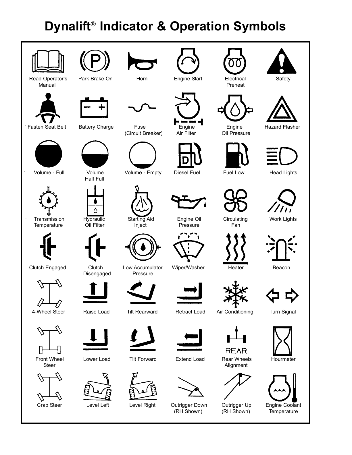
The SAFETY; INDICATORS/CONTROLS; and OPERA-
TION/ADJUSTMENTS chapters for information regard-
ing safe use of the machine.
The LUBRICATION, SERVICE/STORAGE chapters for
information regarding proper maintenance of the machine.
Explain that regular lubrication and maintenance are
required for continued safe operation and long life.
Give this Operator’s Manual and the EMI Safety Manual to
the Customer and instruct them to be sure to read and com-
pletely understand its contents BEFORE operating the
unit.
Explain that the Customer MUST consult the Engine
Manual (provided) for related specifications, operating
adjustments and maintenance instructions.
Completely fill out the Owner’s Registration, including
Customer’s signature and, return it to the company.
Customer’s Signature
Date Delivered
(Dealer’s File Copy - Remove at Perforation)
PRINTED IN U.S.A. 7908424/AP500
Start the machine and test-run the unit while
checking that proper operation is exhibited by all
controls.
Courtesy of Crane.Market