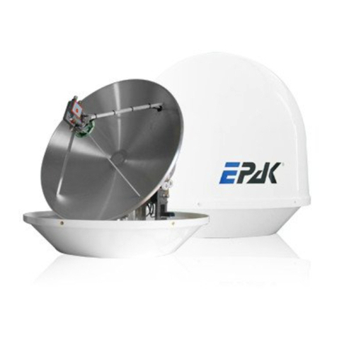
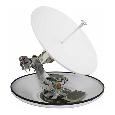
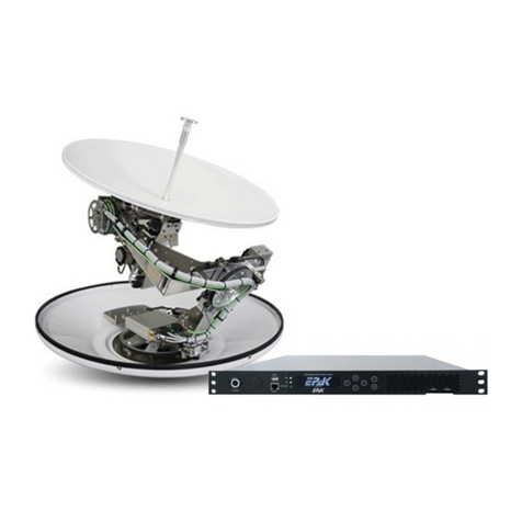
EPAK DS6 PRO User manual

Installation and User Manual
Maritime TVRO systems
DSi6Ku Pro
DS6 PRO
DS9 PRO
DS13 PRO

EPAK Su ort Contact Details
!"#$
%&'
'()&*
+&,-(./01
"+&.23453336(78/-(./'7'(
"&&9&53
5&"#3
TVRO Serial Number
Figure 1: Antenna label with serial number
+"#.33"(:;8/4#323
&3
< 3 "# +=>? " # 23
.@/3324"
Disclaimer
&# # 3" 4 &3 3
"& 3" 3"3 # + " " &233
" && 6 #A 4 3 "
B3# &3233&33"3
"2" &444&53 &#
&364&6""
Co yright
C !"#$23
Trademark acknowledgements
33"5 !"#$

Table of Contents
3
%>""3D
>3
E&"
F3&"
4&&
B"#"&:
1B"#"&?:
%";"&) 1
3 '
+3 '
% '
@7743'
B" '
>3 8
#& 8
(
1>"2+&)5
'3:
84&&+=>?"
(!3
%";#;
G+=>? 7,3%"
?&+=>?" 1
;:& 1
;: (
%7H#3 (
%7HF45
%7H%"
%";
;7HF45
;7H)+
;7H
;7H%
;7H=
1
B 1
13233"& 1
1$34 '
1)F, '
1FB; '
' 8
';: 8
' 8
8! (

1 Introduction
Intended readers
+3" +=>?">?%633
"3 2& 2" "#&&33
*3# ""3#
"63"33"
Product descri tion
+=>? " 5 " += & "3 ""
&& I +=>? " 33 5 &23 += 2 4
&7"&&J"23
%+=>?"4"A6?3:.?:/33:.:/
+?:&3#:=7#*36"""7&63"3"+
7E""64"543A"+"#477
5.4>@52-1-!F%%DFB7&/
"3 5 &3 & K + : ; : .;:/ 3
:&34%&&.:%/
+&234#765I
345
+ &" 3 #6 3 3 I
"A>@ "&6 #36" & 3 3" "&
&"*3"&& @" " 2 & & 6 " 4
"6 +=>?"#&2
?#36"4331K7&3
5"+7&&2242
324&43+2#3
*1"6("3".%16%(3%&2/
233&""3&"+2
23#3&#"#4#3+
4 &2 #5 33 2
""456G@23=&=
Your safety
&4&&"3"&3""5434
&+434&&&"

2 Safety Recommendations & Precautions
2.1 Radar interference
•+"#"34&#"&J33&43
"&"+2346
3#"33220K#2K#43 3
""33 """ 3#4 ?:3L7#3%7,33#
•"&3"6!%6>36=$@6@B6B6
3#3443
2.2 Ex osure to rain / moisture
• & 3 "& ?: 3 ;: 4 23
4&"
•+;:3:%"4#5&3E&6""
3"&"
2.3 Necessity of grounding the equi ment
!3&"23&3#4&J3&
3&"J+J3#33&J3
23334@3&&(!3
2.4 Power su ly
+;:(71=;9'71$*&2D+;:&&;&4
::%"3 "644#"23
@"38
2.5 Maintain ambient tem erature for IDU
&3233&"+;:#3"&
#47K;8K;&6"#"&"#"3#47K;
K;@"#2"3":
2.6 Maintain ambient tem erature for ODU
?& "& ?: "7K; K;6 4 "&
#47K;8K;G"/K;6""#5&23
3"&72"3#3

3 System Com onents List
33326434""&
Com onent Details
ODU Descri tion
•%#*334"3
•@37"#
•#3)F,
•#!%2
•>3""#
Features
•7E""-543A"
•>"2""7K-K
•+5&3&K
ACU (IDU) Descri tion
•;:
•4#3#
Functionality
•;D#"
•B2
•23D2&22
Mounting screws %1%("4
%"4
TVRO manual +=>?"&D"
:&7733"2#343
444&53
Add-ons (O tionally su lied by EPAK)
Com onent Descri tion
LTE Antenna !!?347
UPS ?:%"."3/
Cables ;:
;:)+
@3G
1

4 Installation Procedure
+""&3E+=>?"+23
34434?:3:""33
&373&2"533"2+=>?
"
4.1 Tools required for Installation
@43
3M432 ""387(""3 $E54
5*1
*44
4.2 Select Antenna location
+I3"&324
4.2.1 Free line-of-sight towards satellite
+377&3
22#35&"773&32
33+#3&"
324@#4
4.2.2 Mounting surface requirements
+&3""#3I44"2#
245#"2
,3
2543#3&
,#
3&6##
2"
,&
&#
Figure 4.1: Finding the best location for the antenna
'

4.2.3 Radar interferences
2"&3>33I&
"42 " &" 3 &3 ?: 33
I&"+""""3#44&"
+ """ &# & #4 3 3 3"3 # 3
42 3 &4 "3 # 3 +##44"N"#N
"""&33&4L3%#3"""33
#4&&363""233
X- Band
(~3 cm/ 10 GHz) min distance
S-Band
(~10 cm/ 3 GHz) min distance
Radar Power B""3#4+=>?3>34K2&
75G " "
75G " "
5G- " '"
+&"%L7#3343&"""33
7#3 + 334#" 3 &&
&&23.#A#5&6264
232&"2"/"E3333./3&
4.3 Planning the cable aths
544#3E#)#
3#3534&&&
&I#6"53344
8
Figure 4.2: Minimum safe distance from radar

•:#E#3#33>!1>!43&&""33
#4;:3 43233&"
3"&&4
•+"E""""33#>!1>!"B5#
3E32"E""#62
3#27"&
•23&>@##4"NN
•@3#&&:5#42332
•23ഛ#
•+3;:6#&M3E3#63&#
•:>@
4.4 Drilling
@3"&&&34&733""
#"3"33"&3""+3
323"O80""33B84""334
"6O0""3233""+"6
33B8"4
(

Dimensions and drilling atterns
;5
24
&
;5
24
&
;5
24
&
Figure 4.3: Dimensions 60 cm antenna dome front and bottom)
Figure 4.4: Dimensions 90 cm antenna dome front and bottom)
Figure 4.5: Dimensions 130 cm antenna dome front and bottom)

4.5 Installing the Antenna
,6&54&
Caution:
•+3"#&&E3#&"
•@ 3&6 5 "2" 54626 3
*"Do not o en these trans ortation locks before installation.
Procedure:
•"#333
•+"233#
•B5#"&"
•&""&343""4
•F467&33&&7333
4334+42#"3"#43#
&
•;E##
•;3344&"234&
•@6&&53"#&
4.6 Removing Trans ort Lock of the Antenna
" #
&3"
&"6 &3
"2 & 5
"&
& 5 " #
"23#&4
"6 4 4
"&"
@ 3 3 5
546 26 3
*" "2"
2#33
333
5333
&+&6
&3433
5 4
& ;" # 5
"2"
Figure 4.6: Position of transport locks

Ste 1 > skew "2" #
3&43&
4
Ste 2 > elevation "2"
#33443&
4#4
Ste 3 > roll "2" #
34
#4
Ste 4 > azimuth "2" #
34#4
4.7 Installing the Indoor Unit
,:63#&"4#
3ő@"
##3;543"33"
Figure 4.8: ACU Front view
Figure 4.7: Transportation lock open-closed

+4&3#333:
• : "& .;:-:%/ 3 # "3 & (N 2 5 @
6&3"&3#2#3"
&"#43#3#
•&323:+;:3#34"&
7K;8K;&6"#"&"#"3#47K;
K;
•@5";:634"3&3#5+6,
3#5&;:"#5&42?462"
"34
•:%&233# "&#:%.73#72&/#
3#&4&4:
4.8 Power su ly for TVRO system
+;:(71=;9'71$*6&$426&4&&3#2
3#6&:%"& +=>?"44
#"23+;:&&?:48=;&4
,3;:&&34+#&4=&
&2333;:643#336"3
#&34=
Caution:!3&"23&3#4&J
3&3&"J+J3#33
&J323334
Figure 4.9: ACU top view

4.9 Antenna Grounding
G3643
Case 1:corres onds&""
Case 2:does not corres ond &""
32326&""3&3"
+&2&&"#
34"
Case 1: same otential Case 2: different otential
3 # #3
#4 "" &6 # &
3
#4 ""
&33##3
+#&&3&
& 2 4
&3""+#&"
3"

4.10 System Cable Connections
4&#"5
• &4 4
4523
•&7& 3&3 &
4#43"+423
4&;:
•+;:#3=;
$* " & :%6 4
4 "4#23
• ?: 3 : 36
&3;:3?:
4
•+>2.>L/#.>L-&4/"#3;:
•#3".=)6$)6=$6$$/"#3&"4
•++=23#3&"4
•+;:"#3=$*;"""33:%
•=454#3));:
•+&I".&/2FB#57
&;:
4.11 Wiring TVRO Ku-Band Systems
Figure 4.10 Cable connection with drip loop
.
.
Figure 4.11: Wiring scheme TVRO Ku-Band Systems

5 O erating the TVRO system
?3;:2#33"#36
&47 " &4 && " 3" 5
"3&736&474"
3A&".662654/35"$426
33&"";:I4#7
+;:#"333(75 +=>?"&234#
#"364#3#)F
+6""33";:4#53
+;:3?:2>!>!1E#+>L#2
@3;&4&&+2#30=)6$)6=$6$$
.=)46$*)4=$6$*$/+#3"3
"4+23"4#4#4#33
+=
+&I"& FB ;: 3
"+3"&6363
3#3"!%2E3
+;:33&34)+"3"+)+6"&#)+:B+%
4%B#
53&2#42245;:
5.1 ACU anel
+ +=>?"&3#%#42243#5
&3&3
Front- anel keys:
4%4 %).>L7)56F76F+7/
,%2 @&
;:%,& !&#
)F $%B37%B6%B
4%4 %4;:
$3#;:34
, %2$ +%22"7:%,&3>@&.5
23&"/?#"23#2
3#3
; :%, +&3":%,32
)F +�
;
1
Figure 5.1: ACU Front view

%) %4524>2%6
23%"
>L0.0536#053640F
/
F+0.0;:2)+E
46#0/
%0.30;:640;:/
@ & &;:3
! &, +&52"35
$ %"% +33%B3%B%B
Back-Panel Schematic:
,; !FB; B:3&+=>?
,,; $FB% F:3&+=>?
;%;>% !?;.&/ ?:3&+=>?
GF; P)+ @?
)F; :%, Q%2B4;
@:3&+=>? )>L >B4&3%4
-
,
,;.>P/ :&2 32.
2 63;:6/
:33#
; %;>%.>P/ ;&>%3243#3#
;:
:&33#
GF;.>P/ ;&E4
)F;.>P/ ;&456454;
@ ?&,B;.>P/ :3&+=>?
! FB;.4&/ :&.2#/;:2
"&?#2&
$ FB%%4 %433FB&2
.>%>%>%8/
;33#
!?; ?&E3;:2#4
&&&&
P )+; ;)+&
:%, :&""4;:
) >L.F/ ;;&4";:
B6 B3">L.+F;/ :3+=>?"
'
Figure 5.2: ACU rear view

F6
?
@? +;:&4326"5
2#3
Q %2B; ;&4&&"3"&
> B%4DB&D
@$3
%4;:"&
;;:==;

+&&234;:
3R
Access to the Webinterface:
Connect a com uter to this ort if you need to access the ACU via network.
)F)F4#
33 (18(18
:" 3"
43 S3;:"#>
29&53"&&
8
Figure 5.3: ACU rear view Access to Webinterface

5.2 Accessing the ACU
+=>?"&234##"3 +
&233#;3;:.45/:"&
4##44334
LAN1 LAN2
ACU IP address (18 (18
Subnet Mask
DHCP range (187(18 (187(18
&&3"3&43
32
36&3" +
2 " #
3643
:"3"
43S3;:"#H
Navigation Menu
:&6224&4#3&3
?336F2
" + " 4 4 24 ;:
32" %
Overview54##5$".Overview/&
System Status
242"3"
"+&42;:3<
F2B3&"*"
33
5.2.1 Status -> Dashboard
Dis lay:
(

+#2423#236523%F>3,6#&
6"3.4%?&"*@
?&"*/
%777F7> %
%F"
%
Status LEDS:
+);:7&+>L)&>2%
.!0>L56,0F>L5640F/+3) re resents
F45;:.02)+E46#0
/+)4".>30;:640/
Signal Strength:
+242%F.3,/6&4.3,"/63"#
23
GPS Position:
+434!%&62&3333!%"3
?:
ACU Diagnostics:
+;:3&42&4;:&"&2"3"
%: (In ut Volt/6&3&"#53.fan1 s eed/6"&=2.T12
Tem /6&3&"#3.fan2 s eed/6;:"&3.CPU
Tem /6 = 2 "&.I12 current)6 "& 3;: 3.Rfbrd
tem /62&"33;:.Humidity/
Antenna Diagnostics:
+4342&4&"+?:2
=.ODU Volt/6"&.ODU curr/6233#"
.Rssi/3"&"3?:.ODU tem /
Traffic Overview:
+43445#343;:
Antenna Orientation:
+ 43 4 E&3 .;3/ 3 *"6 26 %54 3 $3
Logged in Users:
+ 43 4 33
3"
Network:
$53345
NMEA status
+#"
FB3"2
&#"*224&+&36
544 <
"&4343#55
"56&5TA lyU&
&2"24
This manual suits for next models
2
Table of contents
Other EPAK Antenna manuals
Popular Antenna manuals by other brands

M2
M2 2M9SSB/FM Assembly manual
PCTV Systems
PCTV Systems teleScope (73a) quick start guide
SteppIR
SteppIR MonstIR PRO DB42 installation manual
AEI Security & Communications
AEI Security & Communications DG258 igiSender HQ2 user manual
Pason
Pason G2 SatAimer user guide

Ventenna
Ventenna HFp Vertical user manual
