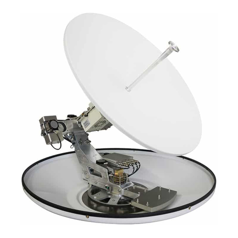
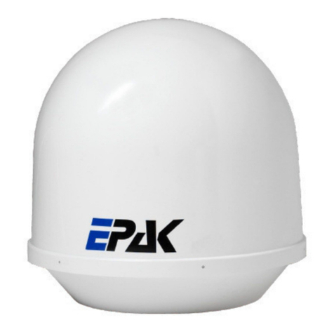
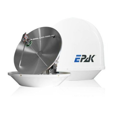
EPAK DSi6Ku Pro User manual

Installation and User Manual
Maritime VSAT systems
DSi6Ku Pro
DSi6Ku Pro
DSi9Ku Pro
DSi13Ku Pro
Doc ID 0304 03.07.20 Page 1/32

EPAK Support Conta t Details
Please contact us for any technical enquiries:
EPA GmbH
Spinnereistr. 7
04179 Leipzig
Telephone Business hours +49 (0) 341 – 2120260
Emergency Telephone (active during weekends and holidays, 9h-18h): +49 (0) 1575-7954223
Email: [email protected]
Please keep your serial number ready.
VSAT Serial Number
Figure 1: Antenna label with serial number
The serial number (standard format: 090UC.10.1843.0000) will be required for all service requests regarding
this product.
You can find the serial number of your EPA VSAT system both engraved on the chassis of the antenna
(Figure 1) and on the delivery note sent to you with the system.
Dis laimer
Any responsibility or liability for loss or damage in connection with the use of this product and the
accompanying documentation is disclaimed by EPA . The information in this manual is provided for
information purposes only, is subject to change without notice and may contain errors or inaccuracies.
Manuals issued by EPA are periodically revised and updated. Anyone relying on this information should
acquire the most current version e.g. from https://www.epak.de. EPA is not responsible for the content or
accuracy of any translations or reproductions, in whole or in part, of this manual from any other source.
Copyright
© 2019 EPA GmbH. All rights reserved.
Trademark a knowledgements
EPA is a registered trademark of EPA GmbH.
Doc ID 0304 03.07.20 Page 2/32

Table of Contents
1 Introduction ...................................................................................................................................................... 5
2 Safety Recommendations & Precautions ........................................................................................................ 6
2.1 Microwave radiation hazard ........................................................................................................................ 6
2.2 Radar interference ...................................................................................................................................... 6
2.3 Exposure to rain / moisture ......................................................................................................................... 6
2.4 Necessity of grounding the equipment ....................................................................................................... 6
2.5 Power supply .............................................................................................................................................. 7
2.6 Maintain ambient temperature for IDU ....................................................................................................... 7
2.7 Maintain ambient temperature for ODU ...................................................................................................... 7
3 System Components List ................................................................................................................................ 8
4 Installation Procedure ...................................................................................................................................... 9
4.1 Tools required for Installation ...................................................................................................................... 9
4.2 Select Antenna location .............................................................................................................................. 9
4.2.1 Free line-of-sight towards satellite ......................................................................................................... 9
4.2.2 Mounting surface requirements ............................................................................................................. 9
4.2.3 Radar interferences ............................................................................................................................. 10
4.3 Planning the cable paths .......................................................................................................................... 11
4.4 Drilling ....................................................................................................................................................... 11
4.5 Installing the Antenna ............................................................................................................................... 13
4.6 Removing Transport Lock of the Antenna ................................................................................................. 13
4.7 Installing the Indoor Unit ........................................................................................................................... 16
4.8 Power supply for VSAT system ................................................................................................................ 17
4.9 System Cable Connections ...................................................................................................................... 18
4.10 Wiring VSAT u-Band Systems .............................................................................................................. 18
5 Operating the VSAT system .......................................................................................................................... 19
5.1 ACU panel ................................................................................................................................................ 19
5.2 Accessing the ACU ................................................................................................................................... 22
5.2.1 Status -> Network ................................................................................................................................ 23
5.2.2 Status -> System ................................................................................................................................. 24
5.2.3 Status -> Logs ..................................................................................................................................... 24
5.3 System Configuration ............................................................................................................................... 25
5.3.1 Configuration -> Modem ...................................................................................................................... 25
5.3.2 Configuration -> Network ..................................................................................................................... 25
5.3.3 Configuration -> Antenna ..................................................................................................................... 27
5.3.4 Configuration -> Satellite ..................................................................................................................... 27
5.3.5 Configuration -> Update ...................................................................................................................... 27
5.4 Account Details ........................................................................................................................................ 27
5.5 Service Activation ..................................................................................................................................... 28
5.6 Maintenance ............................................................................................................................................. 28
6 Hardware configuration ................................................................................................................................. 29
6.1 BUCs ........................................................................................................................................................ 29
6.2 LNBs ......................................................................................................................................................... 29
6.3 Supported Modem Types ......................................................................................................................... 29
6.4 NMEA Connector ...................................................................................................................................... 29
7 Datasheets .................................................................................................................................................... 30
7.1 ACU .......................................................................................................................................................... 30
7.2 Antenna .................................................................................................................................................... 30
8 Glossary ........................................................................................................................................................ 31
Doc ID 0304 03.07.20 Page 3/32

1 Introdu tion
Intended readers
This is an installation and user manual for the EPA VSAT systems PRO Series, intended for installers of the
system and service personnel. Personnel installing or servicing the system must be properly trained and
authorized by EPA . It is important that you observe all safety requirements listed in the beginning of this
manual, and install the system according to the guidelines in this manual.
Produ t des ription
EPA VSAT antennas are automatic satellite tracking systems for internet access made for maritime
applications. Earth Stations on Vessels (ESV) are used to enable broadband access, data
communication, and telephony via satellite links, operating in the fixed satellite service while the vessels
are travelling near the coast or on the high seas. EPA 's VSAT systems are designed to track those
satellites with great precision in real-time response to the ship’s motions even in rough sea conditions and
ensure a seamless availability of the broadband internet connection on the move.
Such VSAT systems consist of two major units, the antenna Outdoor Unit (ODU) and the Indoor Unit (IDU).
The ODU is protected by a UV-stabilized, maritime climate-proof, and easy to maintain radome. The antenna
uses a 3-axis motion system, with automatic skew adjustment. This feature in combination with state-of-the
art tracking technology (twin RF tracking receiver + 6D inertial + GNSS & NMEA - optional) guarantees an
unmatched tracking speed up to 50°/s. The IDU consists of the Antenna Control Unit (ACU) and satellite
modem. The ACU is a device that communicates with the Antenna, the modem and optionally with the
heading data from the vessel.
This unit provides an easy to use web-interface for configuring the antenna, checking the antenna's current
status and configuring your network.
EPA systems can be easily configured in a variety of ways using different LNBs, BUCs and modems to
accomplish individual application needs. To guarantee the highest performance and reliability, EPA
designs and engineers all of its antennas' major RF components, control boards, mechanical parts and
radome in house. All the components are optimized for rough marine applications. From small vessels up to
super yachts, no matter whether sailing or motor yachts, EPA VSAT series are eminently suitable for all
types of vessels.
EPA 's VSAT systems are designed to meet the satellite operators requirements of every ESV for receiving
and transmitting the data via u or a-band. Once the connection to a satellite is established, the system
will stay connected due to a 360° high-speed tracking system. That guarantees a non-stop connection to the
internet while the vessel is anchored or even while cruising in open seas under rough conditions. The
antennas are available in dish sizes in the range of 60cm, 90cm and 130cm (DSi6, DSi9 and DSi13
respectively).
EPA also offers several additional options to accommodate special requirements. The Diversity it assures
the avoidance of blind spots by combining the free line of sight ranges of two antennas in one bundle. This
will prevent any loss of satellite signal through blockages. Additionally EPA also offers a vessel
management router for network control, WiFi services and Voip/Voice connections.
Your safety
All personnel who operate equipment or do maintenance as specified in this manual must know and follow the
safety precautions. The warnings and cautions that follow apply to all parts of this manual.
Doc ID 0304 03.07.20 Page 4/32

2 Safety Re ommendations & Pre autions
2.1 Mi rowave radiation hazard
F
igure 2.1: Microwave radiation safety distance
Ensure that all personnel stay outside of the safety distance during antenna operation.
During operation the antenna uses high-powered BUCs in order to establish a two-way
communication with the satellite. The resulting radiation is hazardous. Note the following points for
your safety.
•Make sure the minimum safety distance of 30m as specified at the ODU is kept when the antenna is
transmitting.
•Our antenna detects if there is a blockage in its transmission path and stops transmission
immediately. However, avoid standing directly in front of the the ADU while it is transmitting.
2.2 Radar interferen e
•The antenna must be mounted as far away as possible from the ship’s radar and high power radio
transmitters as they can affect the antenna performance. To avoid the worst interference, the antenna
should be mounted at a different vertical level – either 15° above or 15° below the radar. indly note
the recommended minimum distances between the ODU and X-band/S-Band radars in the table
4.2.3.
•After the installation is completed all other electronic systems, i.e. GPS, Radar, VHF, FM, AM etc.,
should be tested for full functionality while the antenna is switched on.
2.3 Exposure to rain / moisture
•Do not open sealed electronic components on the ODU and the ACU. Doing that will void the
warranty of the equipment.
•The ACU and the satellite modem must always be kept indoors. Exposure to rain, sunlight or moisture
may damage the equipment.
2.4 Ne essity of grounding the equipment
Grounding of the equipment is necessary to avoid potential differences between the ship’s ground potential
and the equipment’s. The antenna’s ground connection shall be connected directly to the ship’s ground to
avoid undesired current flow.
Doc ID 0304 03.07.20 Page 5/32

2.5 Power supply
The ACU requires 90-264V AC @ 47-63 Hz Input voltage & frequency. The ACU then supplies DC power to
the Antenna. Use of an online UPS is mandatory for EPA systems, otherwise the warranty becomes void.
For more details see 4.8.
2.6 Maintain ambient temperature for IDU
Proper cooling and ventilation is required for all indoor equipment. The ACU can be stored at a temperature
between -40°C to 85°C. During operation, the ambient temperature must be maintained between -20°C to
55°C. Frequent imbalances in the environment can damage the IDU electronics.
2.7 Maintain ambient temperature for ODU
Operating temperature for the ODU ranges from -30°C to 55°C, while the storage temperature range is
between -30°C to 85°C. When temperatures fall below -30°C, the antenna system must be kept on to avoid
damage to electronic parts at re-start. Alternatively an antenna heating system should be used.
Doc ID 0304 03.07.20 Page 6/32

3 System Components List
In our standard delivery, you will find the following system components.
Component Details
ODU Des ription
•Stabilized Antenna Pedestal with electronic control modules
•Feed-assembly
•u band BUC & LNB
•Inbuilt GPS receiver
•Radome assembly
Features
•3-axis motion system + auto skew adjustment
•Range movement from -15° to +120°
•Tracking speed up to 50°/s
ACU Des ription
•Antenna Control Unit
•Power cable and Ethernet cable
Fun tionality
•Configuring satellite & beams
•Monitoring live status of the antenna
•Providing Internet access & voip services to the vessel
Mounting s rews DSi6 / DSi9 4 mounting screws
DSi13 : 12 mounting screws
VSAT manual VSAT manual for easy operation & configuration of the system.
Up-to-date documents are available for download on
www.epak.de/en.
Add-ons (Optionally supplied by EPAK)
Component Des ription
Satellite Modem Supported modem types:
•iDirect modems - Evolution, Velocity platform
•Hughes HX200
•ViaSat SBT-M
•Comtech CDM-250/840
•Gilat series - Capricon, Gilat SkyEdge-II Pro
•Paradise PD25L, Datacom Q-Flex
•SpaceBridge modem
•Tooway
•Romantis / Eastar UHP 1000 / UHP 2000
•others on request
Doc ID 0304 03.07.20 Page 7/32

Vessel Management Router •Network monitoring & control
•Traffic prioritization
•Hotspot management
•Managing Crew calling services
•Web Filtering
PBX equipment Handling SIP service for making low cost Voip calls
IP Telephones For making VoIP calls
UPS Online UPS system
Cables 2x Double shielded coax cable (ECOFLEX10 or 15) with N-Plugs
2x Double shielded coax cable (RG6) with F and TNC-plugs
4 Installation Pro edure
The installation of our systems is easy compared to existing VSAT systems. This section gives a guideline
and answers all your questions on how and where to install the ODU and IDU. It is highly recommended to
plan your installation according to this in-order to prevent mistakes and damages to the vessel or the VSAT
system.
4.1 Tools required for Installation
Following tools are required for installation.
electric drill; screwdriver 4 mm and 8.5-9 mm drills Hexagon socket screw
key size 6
size 13 screw wrench
4.2 Sele t Antenna lo ation
The antenna's selected mounting position should have the following characteristics.
4.2.1 Free line-of-sight towards satellite
The antenna needs a free line-of-sight to the satellite for uninterrupted operation. Any obstacles can reduce
service availability and tracking performance. Please note that the free line-of-sight depends on the vessel
geolocation and the selected satellite. The best location for the antenna is on a raised platform or on one
end of the vessel as shown in Figure below.
4.2.2 Mounting surfa e requirements
The pedestal/mast must be rigid enough to carry the antenna's weight as well as eliminating the vibrations
of the antenna/vessel while tracking/being on the move.
Doc ID 0304 03.07.20 Page 8/32

Bad location: in such a situation it is
very likely to incur a wide blind spot.
Better: by setting the antenna to one
end of the ship, the obstacle can be
overcome.
Best location: if possible, place the
antenna on top of the boat.
Figure 4.1: Finding the best location for the antenna
4.2.3 Radar interferen es
It is very important to not install the antenna near the radar. Radars and satellite antenna's operate in the
microwave region of the electromagnetic spectrum. A radar placed close to the ODU can degrade the
antenna's performance. Thus it is necessary to maintain the minimum distance between the two equipments.
The minimum acceptable separation between a radar and the antenna is determined by the radar
wavelength/frequency and the power emitted by the radar. The table below show some "rule of thumb"
minimum separation distances for radar power at X and S band. As long as the minimum distance listed
below is applied, antenna damage is normally avoided.
Doc ID 0304 03.07.20 Page 9/32
Figure 4.2: Minimum safe distance from radar

X- Band
(~3 m/ 10 GHz) min distan e
S-Band
(~10 m/ 3 GHz) min distan e
Radar Power Minimum distance between VSAT and Radar with 20° vertical separation
0-20 kW 1.0 m 2.0 m
20-50 kW 2.0 m 4.0 m
50 kW+ 3.5 m 7.0 m
The presence of one or more S or X-band radars within a radius up to 100m may cause a minor degradation
of the u-band connection. The degradation will be most significant at high radar pulse repetition rates.
Especially in poor receiving conditions (objects blocking the signal path, heavy rainfall or icing, low satellite
elevation and violent ship movements) the small extra degradation due to the radar(s) could cause poor
connection quality.
4.3 Planning the able paths
Please check which walls are suitable and if existing openings can be used for the cables. Laying the cables
is usually done by an electrician in the dockyard with proper certificates to alter the ships installations or the
ships structure. If you're in charge of laying the cables, make sure it is done in accordance with the following
rules:
•Use suitable coax cables: double shielded EcoFlex 10 or 15 is recommended. EPA warranty does
not cover decreased performance due to improper wiring.
•The maximum recommended cable length for EcoFlex10 is 50 m and Ecoflex15 is 80 m. Make sure
that the cable length does not exceed this value. If maximum cable length is too short for your
installation, favour higher grade cables over in-line amplifier.
•Avoid placing RF cables too close to other cables which might carry "noise".
•Fit and secure cables properly. Use shrink tubing with heat activated adhesive to seal connectors.
•Avoid sharp bends and kinks on cables.
•To connect antenna and ACU, use cables in one piece; do not extend cables, do not split cables.
•Use only high quality RF connectors.
4.4 Drilling
For an ideal mounting of the antenna all possible drilling patterns are prepared with a pre-drilled hole of 2 mm
in the bottom of the radome. Please refer to the included templates for the drilling measurements. The drilling
should have a diameter of Ø 8.5 – 9 mm for the included M8 screws. It is recommended to start with a
smaller hole, using a Ø 3.5 – 4 mm drill to avoid any damage to the mounting surface. To mount the antenna,
only use the included M8 mounting screws.
Doc ID 0304 03.07.20 Page 10/32

Dimensions and drilling patterns
Click for full
view or refer
to page 29
Click for full
view or refer
to page 30
Click for full
view or refer
to page 31
Doc ID 0304 03.07.20 Page 11/32
Figure
4.3: Dimensions 60 cm antenna dome (front and
bottom)
Figure 4.4: Dimensions 0 cm antenna dome (front and bottom)
Figure 4.5: Dimensions 130 cm antenna dome (front and bottom)

4.5 Installing the Antenna
Before installing the antenna, please take the following precautions:
Caution:
•The radome has to be properly fixed on the antenna before installing it on the platform.
•For safety during transport, the antenna has locks for the movement in skew, elevation, roll and
azimuth. Do not open these transportation lo ks before installation.
Pro edure:
•Ensure that the mounting base is solid and steady.
•The antenna unit must have a clear line of sight to the satellite and there should be no interference.
•Make sure that the cable lengths are sufficient to reach the mounting platform. Recommended
maximum length is 50 m for ECOFLEX10 cables, and 80m for ECOFLEX15 cables.
•Prepare the mast / mounting pedestal with the drilling measurements shown in section 4.3.
•Now, attach a 4-part sling around the antenna to lift and place the unit on the pre-drilled holes and
fasten it with the included screws. The screws have to be mounted from below and through the base
plate of the antenna.
•Connect both the coaxial cables (RX and TX) at the base of the antenna.
•Close all drilled holes with waterproof sealing material to avoid any water penetration.
•Finally, open all the transportation locks according to our manual before operating the antenna.
4.6 Removing Transport Lo k of the Antenna
After the system has been
securely placed on the mounting
platform, only then proceed to
remove the transportation lock.
It is important to note that the
transportation lock must be
removed before powering on the
system, otherwise this will
impose strain on the mechanics
of the antenna.
Four handles are used to lock
the skew, elevation, roll and
azimuth movement of the
antenna. A visible red dot on the
handle indicates that the handle
is locked. A green dot indicates
that it is open. To open or close,
pull the handle towards you and
turn until it locks in the new
position. Confirm by checking
movement of the antenna.
Doc ID 0304 03.07.20 Page 12/32
Figure 4.6: Position of transport locks

Step 1 Release the skew movement by
turning the handle into upward position as
shown in the figure.
Step 2 Release the elevation movement
by turning the handle to downward position
as shown below.
Step 3 Release the roll movement by
turning the handle to the right as shown in
the figure below
Step 4 Release azimuth movement by
turning the handle left as shown below.
4.7 Installing the Indoor Unit
Before installing the IDU, find a suitable location for the equipment within cable lengths. Ensure that the
display of the control unit can be easily read and the front-panel is accessible. Also, allow sufficient room for
connecting the cables behind the control unit. Check the following diagram to find the dimensions of the unit.
Doc ID 0304 03.07.20 Page 13/32
Figure 4.8: ACU Front view
Figure 4.7: Transportation lock open-closed

The following points need to be considered during installation of the IDU
•All IDU components (ACU+Modem) should be mounted in a professional 19" server rack. For the
installation, operation and maintenance enough space should be available at the front and also some
space must be allowed behind the unit for the cables.
•Proper cooling and ventilation is required for all IDUs. The ACU should be stored within a temperature
range of -40°C to 85°C. During operation, the ambient temperature must be maintained between -20°C to
55°C.
•Fresh air intake is from the front of the ACU, and warm air is dispensed out the back. Therefore, Both
front and back panel of the ACU must be kept clear to allow ventilation. Otherwise, overheating might
cause system shutdown.
•Either the UPS is provided by EPA or a compatible UPS (on-line/double-conversion type) has to be
installed by the ship owner for powering the IDU.
4.8 Power supply for VSAT system
The ACU requires 90-264V AC @47-63 Hz, 1 phase. However, as the power supplied by vessel generators
can fluctuate considerably, an online type UPS is compulsory for EPA VSAT system otherwise the warranty
becomes void. The ACU supplies the ODU with 48V DC power and the BUC with either 24V or 48V
depending on the model. There is also a switched AC outlet at the back of the ACU which can be used for the
modem’s power supply.
By default the ACU is equipped with a 2.5A fuse. This is suitable for operation with 230V. A spare 5.0A fuse is
provided alongside the ACU, which should be used instead, in the rare case that the antenna system should
be operated with 110V.
Caution: Grounding of the equipment is necessary to avoid potential differences between the ship’s
ground potential and the equipment’s. The antenna’s ground connection can be connected directly to
the ship’s ground to avoid undesired current flow.
Doc ID 0304 03.07.20 Page 14/32
Figure 4. : ACU top view

4.9 System Cable Conne tions
Please note the following points before making
the connections.
•Ensure to power off the circuit which
you are working on to avoid any short.
•Drip-loops should precede the entry
point as shown in below diagram. This will
avoid any water to seep into the ACU.
•The ACU has to be connected to 230V
AC 50Hz from a online type UPS, otherwise the
warranty on EPA system will be void.
•
After the ODU and IDU are installed, proceed to
connect the ACU and ODU as follows:
•The two antenna cables (RX+power and TX) must be connected to the ACU and the ODU.
•The modem cables (RX, TX and WAN) must be connected to the ACU.
•The ACU must be connected to 230V/50Hz AC from our recommended UPS.
•Vessel network or switch can be connected to Lan1 /Lan2 of ACU.
•The modem must be powered by the ACU with provided power cable.
•The user can also connect the ship's gyro information (optional) via the NMEA connector at the back-
panel of the ACU.
4.10 Wiring VSAT Ku-Band Systems
Doc ID 0304 03.07.20 Page 15/32
Figure 4.10 Cable connection with drip loop
Figure 4.11: Wiring scheme VSAT Ku-Band Systems

5 Operating the VSAT system
Once the Antenna and ACU have been installed safely and all the system cabling is connected, you can
power-on the system. Please refer to the power supply requirements of this document to check the
requirements. If there is already a pre-configured satellite, after powering-on the antenna will automatically
adjust all its parameters (sensor, gyro, elevation, skew etc) and lock onto the satellite automatically. However,
the user can also easily configure the desired parameters from the ACU's web-interface.
The ACU has to be mounted into a standard 19-inch rack. All EPA VSAT systems provide a web interface for
basic monitoring and configuration, which can be accessed by connecting to any one of its LAN interfaces.
Therefore, it is recommended to mount the ACU where the antenna status can be checked.
The ACU is connected to the ODU via 2 coaxial cables RX and TX. The RX cable carries the receive signal in
IF, and the DC power supply for the antenna. The TX cable carries the transmit signal in IF, reference signal
for the BUC and power for the BUC.
The ACU is connected via two coaxial cables (RX & TX) and one Ethernet cable to the satellite modem. The
ACU forwards the IP traffic from the modem to its own LAN interfaces.
You can also connect the ship's compass to the NMEA interface of the ACU for accurate heading information.
This heading information is optional, so if it is not connected,the antenna relies on the heading data obtained
from the GPS receiver fixed to the antenna.
Please check the description given below for a short overview of the key functions of the ACU.
5.1 ACU panel
The EPA VSAT system is operated by the control unit. See below a short overview of its front and back
panel and its corresponding functionality.
Front-panel keys:
A: Power Switch E: Status LEDs
B: Service Port F: Display
C: USB port G: Input buttons
D: LAN1 connection H: SIM card slots- SIM1, SIM2
A Power Switch Switch the ACU on or off.
Hold this button for 2s to force the ACU to shut down.
B Service Hatch The Service hatch covers a micro-USB port and a RF port (to check
received signal spectrum) .Only to be removed by service technicians
or if you are instructed by a technician to do so.
C USB Port This port is used to mount a USB drive.
D LAN1 Port This port can be connected to your local network, a network switch or a
PC
E Status LEDs Shows a quick view of the status of the RX, TX and Network status
Doc ID 0304 03.07.20 Page 16/32
Figure 5.1: ACU Front view

F Display Displays the current status of the ACU and antenna.
G Input Buttons The input keys lets you navigate the menu and access quick settings.
H Sim Slots The user can insert standard SIM cards in SIM1 or SIM2
Ba k-Panel S hemati :
A: IDB1 Connector G: NMEA Connector M: Modem RX
B: IDB2 Connector H: NMEA Protocol Select N: Modem TX
C: Serial Connector RS232 I: GPIO Connector (opt.) O: Antenna TX
D: WAN Connector J: LTE Antenna connector P: Fan Outlet
E: LAN 2 Connector : USB Port Q: Slave Mains Power Connector
F: Open BMIP Connector L: Antenna RX R: Mains Power Input and Switch
A
+
B
IDB Connector (RJ45) Use these ports to connect several EPA devices together (e.g.
Div it, second ACU, heating controller).
Use only if you are instructed to do so by a technician.
C Serial Connector RS232 (RJ45) Connect this port to a RS232 device which should be controlled by
the ACU.
Use this port only if you are instructed to do so by a technician.
D WAN Connector (RJ45) Connect this port to the WAN port of your modem.
E LAN 2 Connector (RJ45) Connect this port to your local network, a network switch or a PC.
F Open BMIP Connector (RJ45) Use this port to connect a modem which supports Open BMIP.
Use only if you are instructed to do so by a technician.
G NMEA Connector (two pole) Use this port to connect (if available) the ACU to your vessels
compass. Observe correct polarity.
H NMEA Protocol Select Switch Set this switch according to the used NMEA protocol on your vessel
(RS232 or RS422/RS485).
Change only if you are instructed to do so by a technician.
I GPIO Connector Optional connector to extend the ACUs connectivity by two general
purpose inputs or outputs.
J LTE Connector Connect the LTE antenna to this port
USB Port Use this port to communicate serially with the ACU
L Antenna RX (N) 1 Connect the RX cable from the antenna to this port.
M Modem RX (TNC) Connect to the RX port of your modem.
N Modem TX (TNC) Connect to the TX port of your modem.
O Antenna TX (N)³ Connect the TX cable from the antenna to this port.
P Fan Outlet The ACU is a high power device, make sure that the fan outlet is
never obstructed.
Doc ID 0304 03.07.20 Page 17/32
Figure 5.2: ACU rear view

Q Slave Mains Connector Connect the power supply of your modem to this port.
R Mains Switch & Mains Input &
Fuse Holder
Switches the ACU off completely.
Connect the ACU to a 110V or 230V AC outlet.
Access this hatch to replace a broken fuse.
1 Those connectors carry the supply for the BUC and antenna. Do not connect or disconnect while the ACU is
turned on!
A ess to the Webinterfa e:
Conne t a omputer to this port if you need to a ess the ACU via network.
Access: Lan2 with ethernet cable
Address: 192.168.2.254
Username: admin
Password: (empty)
Please contact [email protected] for remote support.
Doc ID 0304 03.07.20 Page 18/32

5.2 A essing the ACU
All EPA VSAT systems provide a web interface for basic monitoring and configuration. The connection
interface is provided by any PC connected to the ACU (through a local network connection). Users can simply
use their web browser to access this functionality without additional software installation.
LAN1 LAN2
ACU IP address 192.168.1.254 192.168.2.254
Subnet Mask 255.255.255.0 255.255.255.0
DHCP range 192.168.1.1 - 192.168.1.200 192.168.2.1 - 192.168.2.200
Enter the supplied username and password to gain
access to the features. If you do not have the login
details, please contact your administrator or EPA IT
service. In case your system has not been
configured yet, use the following credentials:
Username: admin
Password: <empty line no spaces>
Navigation Menu
Upon successful login, the user overview page will be displayed on the
screen. On the left hand side of the screen, you can see the Navigation
menu. This menu shows the sections where you can view the ACU
status and change various configurations of the system. Selecting the
verview link will bring you back to the Home ( verview) page.
System Status
In this section you can view various system states and monitor the health
of the system. This page shows the live status of ACU and antenna. You
can access the Navigation Menu and the Display customization menu on
the left hand side of this screen.
Status -> Overview
Doc ID 0304 03.07.20 Page 19/32

Display:
Here you see the current SNR in dB, the TX state, the satellite position, the current antenna state, the current
heading (from external NMEA or if its not connected, from the GPS data), the online status and the orbit
position. Please find the detailed layout below.
Signal-Strength TX State Satellite Position
Satellite Name
Antenna State
Traffi Overview:
This widget shows the network bandwidth of each interface of the ACU.
Satellite Azimuth*:
This shows the expected azimuth direction to the configured satellite and the heading of the ship.
Satellite Elevation*:
This widget shows the expected elevation of the antenna to the configured satellite.
Satellite Skew*:
The satellite skew refers to the axial rotation of the feed/LNB assembly. This is necessary so that the dish is
lined up exactly to the same horizontal/vertical position of the satellite in the sky. This widget shows the
expected satellite skew angle of the dish.
* Note: The Satellite Azimuth, Satellite Elevation and Satellite Skew widgets are not necessarily showing the
current direction and position of the antenna pointing. They are showing the “correct” direction to the satellite,
antenna elevation, and skew calculated according to the antenna’s GPS position.
The ship's heading (Sat Azimuth) is only correct if the NMEA input from ship's compass is used or if the vessel
is moving with at least 1kn.
GPS Position:
This widget shows the current GPS position, vessel speed and the UTC date and time.
Logged in Users:
This widget shows the IP addresses of all the users
currently logged in to the system.
Signal Strength:
Here you can see the live SNR in dBs.
Network:
Here you can check the IP addresses of all the network
interfaces.
It is possible to customize the overview page. To proceed,
click on the arrow icon as shown on the right. You can
simply show/hide each widget by clicking on the links. After
making changes, please click on “Apply” at the top of the
page to save your custom view.
5.2.1 Status -> Network
The Network Page shows the network traffic on each network interface on hourly and monthly basis. You can
also check the live network traffic on the dynamic graphs on the right-hand side of the screen.
Doc ID 0304 03.07.20 Page 20/32
This manual suits for next models
2
Table of contents
Other EPAK Antenna manuals
Popular Antenna manuals by other brands

Ubiquiti
Ubiquiti air Grid M2 AGM2-HP-1114 quick start guide

Sirio Antenne
Sirio Antenne SB 1 S installation manual

GME
GME MB042 quick start guide
Funkwerk
Funkwerk LTE 800 MIMO installation instructions

Parsec Antennas
Parsec Antennas AKITA LITE installation instructions

Wilson Electronics
Wilson Electronics 301133 installation guide
