EPAK Premium Line TV61TV90 User manual

MANUAL
Premium Line TV61 & TV90
English
1

MANUAL
Premium Line TV61 & TV90
English
The technical data, information and illustrations contained in this publication were to the best of our
2

knowledge correct at the time of printing No liability can be accepted for any inaccuracies or
omissions in the publication, although every care has been taken to make it as complete and accurate
as possible
v3
Table of Contents
1 The digital satellite tracking system...................................................................................................4
1 1 EPAK®-TV system overview 5
1 2 Safety recommendations 6
2 Installation............................................................................................................................................
2 1 Standard delivery 7
2 2 Installation overview 7
2 3 Selecting location 8
2 4 Mounting surface 9
2 5 Planning the cable paths 9
2 6 Power supply 9
2 7 Drillings 9
2 8 Mounting the antenna unit 12
2 9 System cable connections 12
3 Control elements.................................................................................................................................13
3 1 Control unit 13
3 2 Preparing the receiver 13
3 3 Power On, Off and Standby 13
3 4 Password access to Setup menu 14
3 5 Adjusting the setup parameters 14
4 TV operation.......................................................................................................................................15
4 1 Stop Tracking function in harbors 16
5 Satellites...............................................................................................................................................1
5 1 Adding new satellites 17
5 2 Update of satellite data base 18
5 3 Delete stored data 19
5 4 Selection of stored satellites 20
5 4 1 Manual selection of satellites 20
5 4 2 Automatic selection of satellites 20
6 Miscellaneous......................................................................................................................................21
6 1 Compass calibration 21
6 2 Adjustment of the LNB type 22
6 3 Special functions via the standby mode 22
6 4 Fastscan function (US only) 23
APPENDICES.......................................................................................................................................24
A Maintenance.......................................................................................................................................24
B Overview of menu structure.............................................................................................................25
C Troubleshooting.................................................................................................................................26
D Skew settings......................................................................................................................................2
E Tracking Modes.................................................................................................................................28
F Replacement parts.............................................................................................................................28
G Technical specifications....................................................................................................................29
3
1 The digital satellite tracking system
The advanced technology in the satellite tracking system EPAK-TV makes it possible to have an
excellent television reception wherever you are Due to an unlimited 360° high-speed tracking, a non-
stop access to your favorite channels is guaranteed even during your trip on a vessel in open seas
The satellite tracking system is protected by a UV-stabilized and maritime climate proof radome, easy
to handle and maintain (Please note that the given warranty for the radome is limited to the terms of
the radome manufacturers Please see details on www epak de/download/radome_warranty pdf) High-
speed tracking sensors developed for this system, using high-tech components of the electronic signal
processing, provide the topmost and dynamic tracking accuracy of the satellite tracking system With
the help of this technology, EPAK-TV guarantees an unmatched tracking rate, dynamic and system
performance EPAK-TV is suitable for any size vessel including smaller boats of less than 36ft (11m)
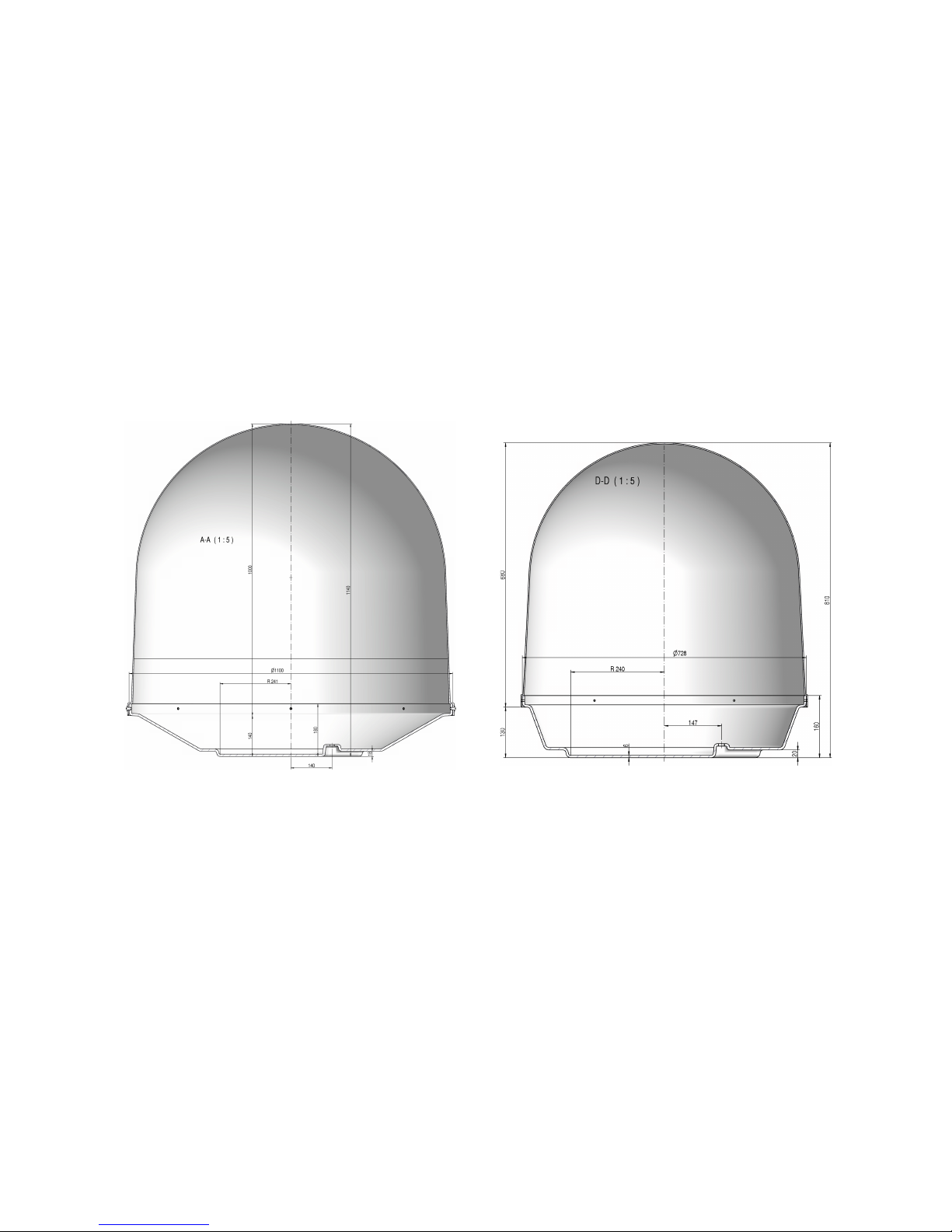
The automatic satellite tracking system includes a reflector antenna dish of 18" (45cm), 24" (60cm) or
35" (90cm) in diameter that is capable of tracking horizontally and vertically to make an amazing
choice of channels available – just like home
Once the connection to a satellite is established, the tracking system will stay connected to the correct
satellite even in the roughest sea conditions
TV90 TV61
Notice! Don’t use alcohol or dilution or similar products for cleaning the radome!
Note! The reception of programs in different regions depends on the footprints of the satellites.
Also, the TV reception can be affected by rain, snow, dense clouds and extreme movements in
areas of weak signals and there is no warranty for receiption of certain channels.
4
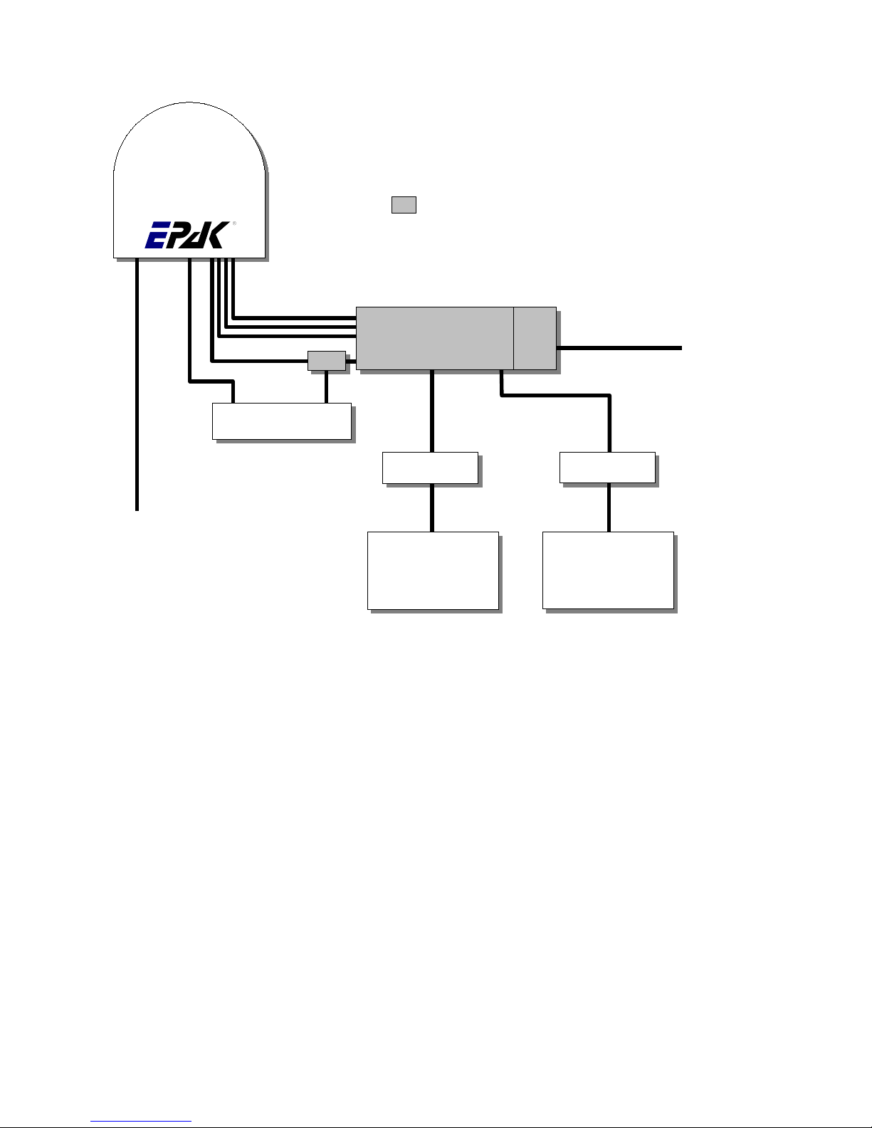
1.1 EPAK®-TV system overview
Multi User configuration with Quattro EU Antenna
All receivers have independent access to all TV channels of all 4 bands Can switch antenna on/
off Only Control Unit can change sat-position
Type 1 Double shielded satellite coax cable (75 Ohms) with F-connectors (one-wire)
Type 2 Double shielded satellite coax cable (75 Ohms) with F-connectors (five-wire in one coating)
Type 3 AV cable or Antenna cable (depends on user’s installation)
Type 4 Power cable (min 2 x 1 5 sqmm), max length 15 meters
5
Antenna
Multiswitch
Antenna Power
12 to 36 VDC
Type 4
Receiver 1
TV 1 ...
Receiver n
TV n
Type 1
Type 1
Type 1
Type 3 Type 3
HV
HH
LV
LH
Control Unit
ReceiverAntenna
Power
upply
Power 220VAC
(Power cord included)
Bias
Part of Multiuser-Kit

1.2 Safety recommendations
➔Please note that the maximum power voltage for the antenna unit must be between 12 and 36
volts DC, and the overload protection should be rated min 5 amp and max 7 5 amp
➔When mounting the antenna, the distance from the antenna unit to other radiation sources e g
radar equipment or other antennas (mobile communication antennas) should be min 2 5 m (8
ft)
➔Simultaneous operation of radar and satellite antenna may damage the satellite antenna if not
installed directly above the radar antenna
➔Do not use the control unit outdoors
➔During a thunderstorm, we recommend that the connection cables are disconnected
➔If the negative side of the antenna unit’s supply voltage has no connection to ship’s ground
(earth), then the antenna unit’s ground point should be connected directly to ship’s ground
(earth)
➔After the installation is completed, all other electronic systems i e GPS, Radar, VHF, FM, AM
etc should be tested for full functionality, while the antenna is turned on
➔Do not test or turn on the antenna before the radome is fitted correctly If the sun reflects into
the dish, the electronics can be damaged
➔Do not touch the rotary joint
➔Do not attempt to open the sealed electronics, as this will void the warranty
6

2 Installation
2.1 Standard delivery
The satellite tracking system EPAK-TV comes complete with electronic assemblies and other
necessary installation material
System components:
●Antenna unit (with serial number)
●Control unit
●Four mounting screws M 8
●Manual
Please check the completeness of all components Make sure that no transport damages exist before
you start the installation
2.2 Installation overview
The installation work has to be done in the following order:
●Select location
●Check the mounting surface for stability
●Check cable path
●Position of power distributor
●Drill holes and lay the cable
●Install antenna unit (see also addendum for instructions of how to remove the transportation
lock before power-up)
●Make all installation openings watertight
●Connect cables
For the installation the following tools are needed:
●Electric drill
●One 4mm and one 8 5-9 mm bits
●Hexagon socket wrench size 6
●Wrench M 8
☛ Plan the entire installation first! To avoid mistakes or damages to the boat or satellite tracking
system, please read the installation instructions carefully before starting the installation.
7
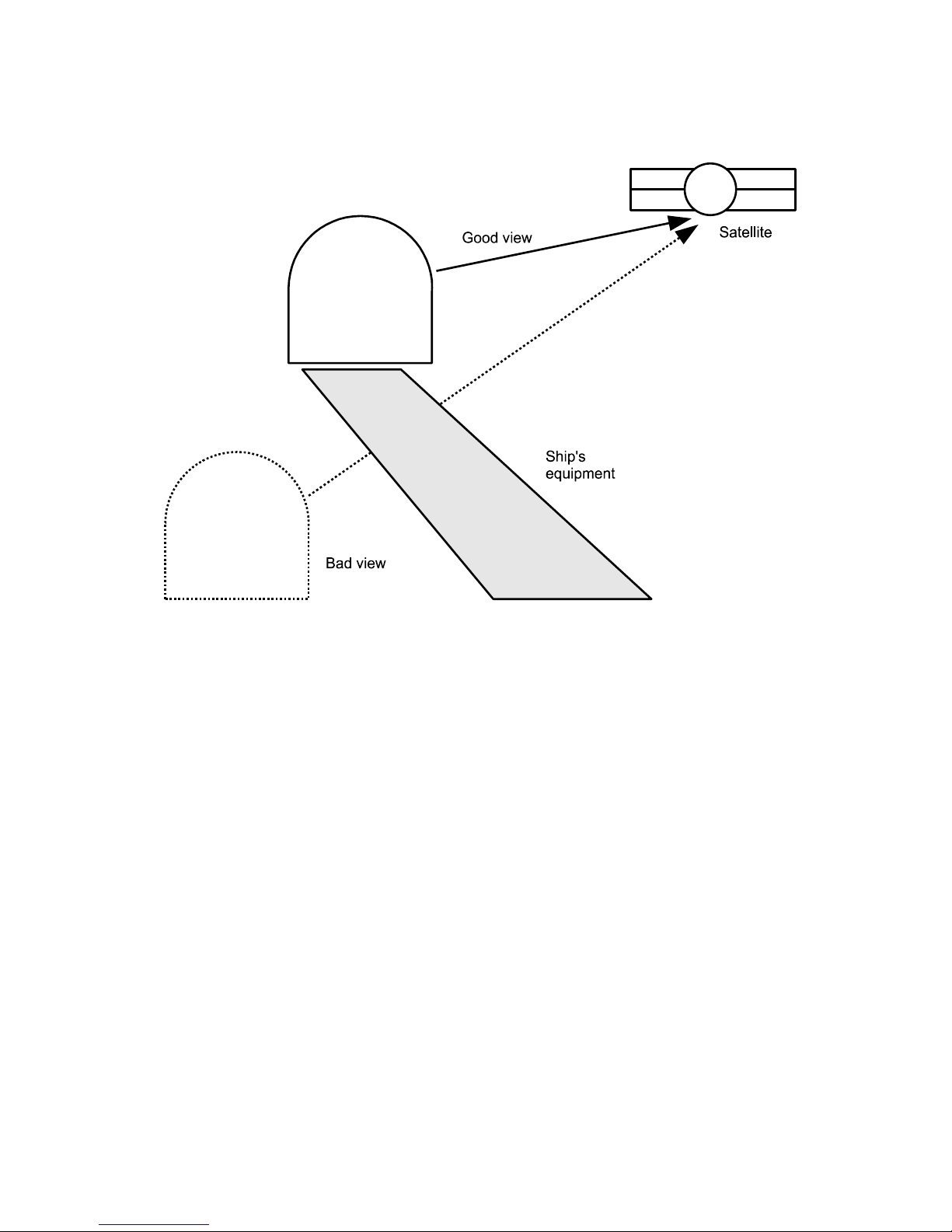
2.3 Selectin location
This illustration shows the importance of a proper location for the antenna unit
Note that criteria such as an unobstructed view to the satellite and a strong mounting surface are met
Furthermore, no sources of interference, e g radar equipment or other antennas, such as mobile
communication antennas, should be installed nearby the Marine TV antenna unit A minimum distance
of 8-12 ft (2-3 meters) has to be observed in order not to affect the picture quality
Although the radome is sealed, it is recommended to avoid direct waves and bilge water!
The antenna unit has to be installed so that no superstructures will obstruct the sight to the satellite!
Please note, that the elevation angle depends on the geographical location of the boat and on the
selected satellite!
☛ Equally important for a good installation are the conditions of the mounting surface and the
lengths of the different cables. See section 2.4, 2.5 and 2.6.
8
Antenna
Antenna

2.4 Mountin surface
A horizontal, solid and steady surface is very important Make sure that the surface does not have any
irregularities! Furthermore, please take into consideration that the weight of the antenna unit is 56 kg
or more Therefore, the surface has to be strong enough to carry the antenna unit, even during the most
challenging maritime conditions
2.5 Plannin the cable paths
Before starting the installation, you should check which walls are suitable and if existing openings can
be used for the cables
☛ All openings have to be sealed in order to avoid any water penetrating.
The control unit should be placed as close as possible to the receiver The maximum length of the
cable is 3 meters Refer to Appendix F for data concerning appropriate cable types
2.6 Power supply
The antenna unit can be connected directly to any ship’s power supply net of 12/24/32 volts DC The
circuit fuse should be rated for min 5 amperes and max 7 5 amperes! (See appendix H “Technical
Specifications”)
☛ The power distributor must be idle while working on the ship’s supply net or you may short
circuit the system.
If the negative side of the supply voltage of the antenna unit has no connection to the boat ground,
make sure a potential compensation between boat ground and the ground point of the antenna unit is
made
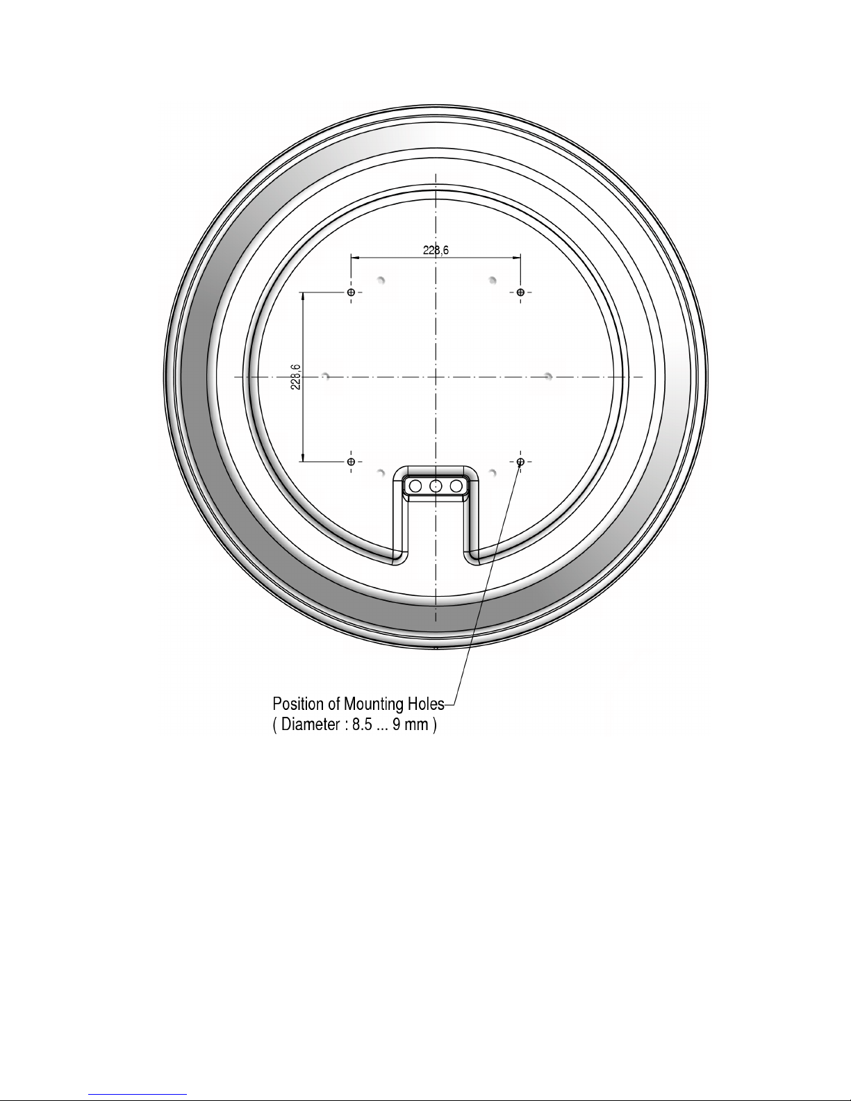
2.7 Drillin s
To avoid any damage to the mounting surface it is recommended that you start out with drilling a
smaller hole, using a 3 5-4 mm bit before drilling the correct hole size Use an 8 5-9 mm bit to drill 4
mounting holes for the M8 screws included To drill the holes in the correct positions, please refer to
the included template
9
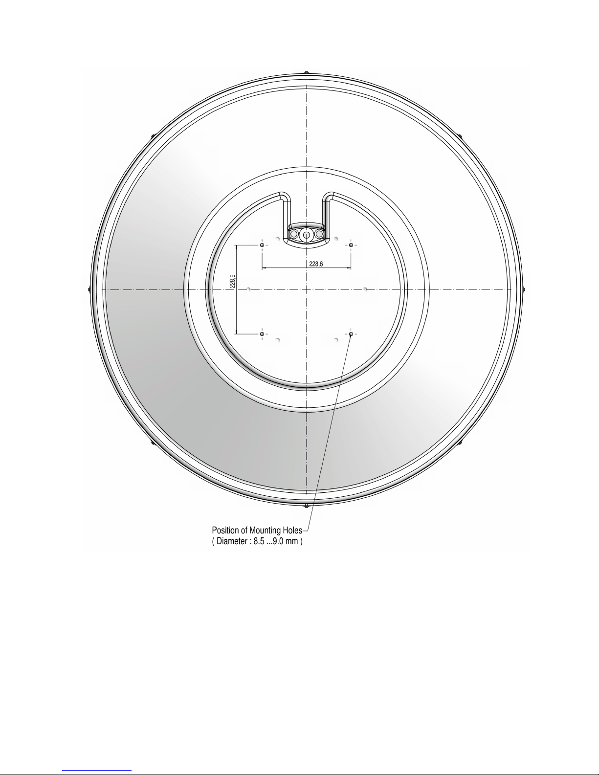
Example of template:
Bow
View from below TV90
10
Bow
View from below TV61
☛ If the antenna unit is mounted on the cabin roof (not device carrier or separate mounting
plates) close all drillings with waterproof sealing material to avoid any water penetrating!
11
2.8 Mountin the antenna unit
The antenna unit has to be mounted on a solid and steady surface Take care that the cable lengths are
sufficient, the antenna unit must have an unobstructed view to the satellite and there must be no
interference fields (especially mobile communication antennas) nearby
Place the antenna unit on the pre-drilled holes and fasten it with the included screws and washers The
screws have to be screwed in from below through the mounting surface into the radome
☛ Close all drillings with waterproof sealing material to avoid any water penetrating!
2.9 System cable connections
☛ Break the contact of the circuit on which you are working to avoid short circuit the system.
●The antenna cable must be connected to the control unit and the antenna unit
●The power supply cable to the power distributor and the antenna unit
●The receiver cable to the control unit and the receiver
See system overview and illustration details in Appendix F and at the end of the manual
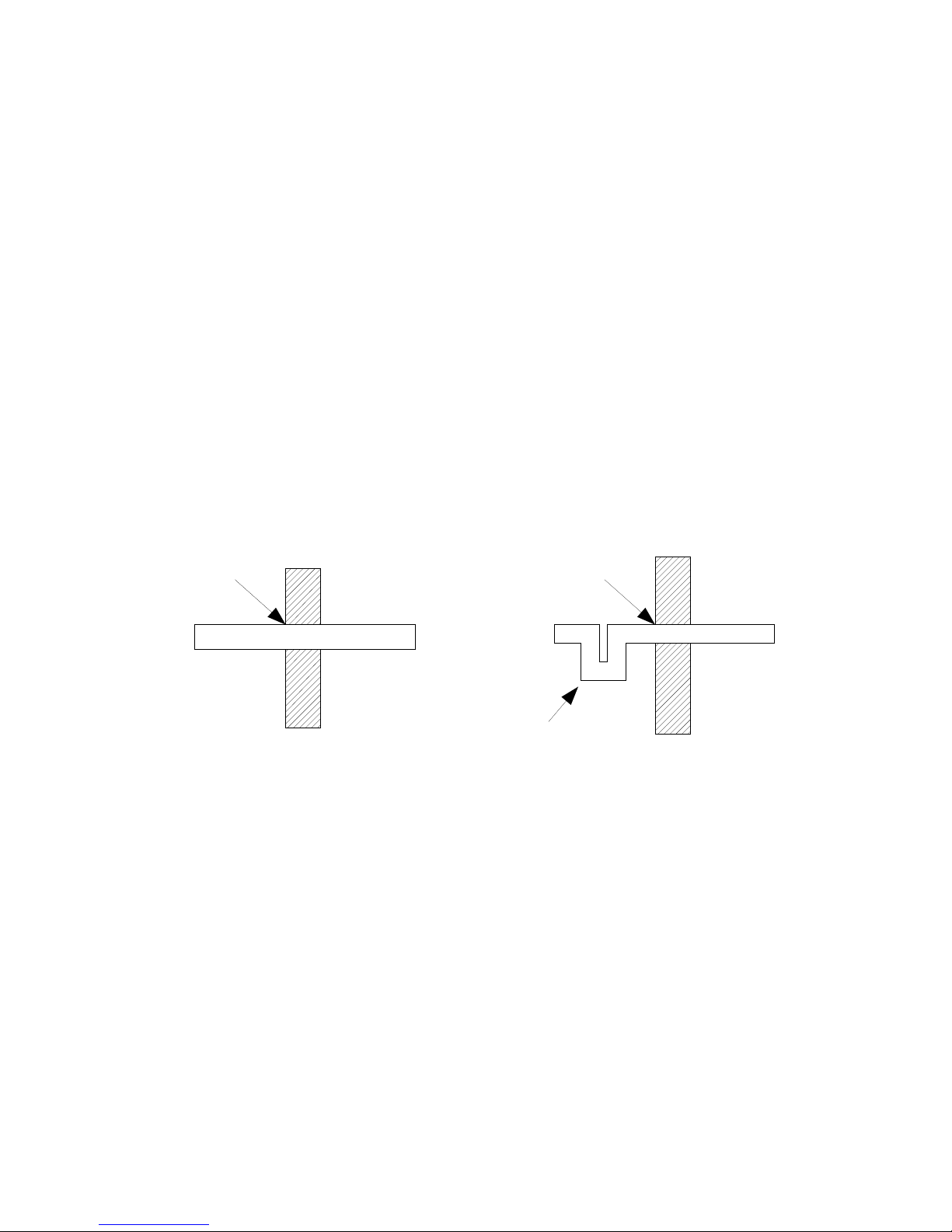
Lead the cable through the drilled holes and seal it with waterproof sealing material Furthermore, drip
loops should precede the entry point from the exterior to avoid any water penetrating, see below
illustration:
Find a suitable location for all units within cable lengths That means that the control unit should be
placed nearby the receiver Take care that the display of the control unit can be easily read and the
push-buttons are accessible And also, allow room for the cables behind the control unit!
The antenna unit is separated from the power supply net by the control unit Therefore, the antenna
unit has electric power when the control unit is turned on!
12
sealing
Cable
Boat
sealing
Cable
Boat
Wrong Correct
Drip loop
3 Control elements
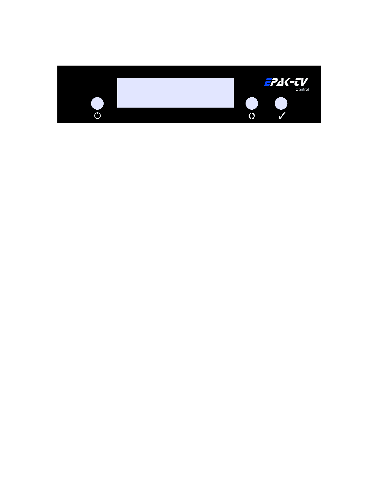
3.1 Control unit
The operation of the EPAK-TV system is controlled from the control unit It is a good idea if you
make yourself familiar with the key functions and to memorize their usage in the menu structure:
Power key: Short press will turn on the power or will enter Standby mode after initialization
Browse key: Short press will browse through all available menus, step by step
Select key: Short press will select/confirm what is written in the display
☛ From the Standby mode: Hold Select key pressed while using the Browse key to scroll through
available data: serial no., operation time, and software versions. See section 6.3.
3.2 Preparin the receiver
EPAK-TV does not need a special receiver The satellite tracking system can be connected to any
commercial receiver for digital and analogue reception Only the LNB-type in the setup menu of the
receiver has to be set on “Universal” (LOF 9,75/10,6 GHz) If you want several satellite positions, the
DiSEqC ™ function for an automatic satellite switch has to be activated
To program your receiver, please refer to the respective owner’s manual!
For every satellite at least one program must be preprogrammed in the receiver to control the
satellite position of the antenna unit by means of the TV picture quality If not, preprogram the
receiver by using an already installed satellite system!
In case the receiver supports the function, adjust the receiver so that the power supply of the
LNB is turned off during the standby-mode This means that the control unit and the antenna
unit are without power supply This function enables the turning on and off of the antenna unit
via remote control of the receiver, which lowers the power consumption
In case several receivers are connected to the antenna simultaneously (e g a digital receiver
with analogue receiver looped through) both receivers must have identical DiSEqC ™ settings
i e active or inactive
3.3 Power On, Off and Standby
The antenna unit is controlled by the control unit, which is turned on by pressing the (power) key
To enter Standby mode, press the key from any menu after the initialization is completed
☛ When the control unit is in standby mode there will be no power supply to the antenna.
13

3.4 Password access to Setup menu
To gain access to the setup menu will require that you first enter a password It is always the same
password which have to be entered When Setup is flashing in the display:
1 Press The display will show: ----
2 Press The display will show: X---
3 Press The display will show: XX--
4 Press The display will show: XXX-
5 Press The display will show: XXXX
The time between each keystrokes should not exceed two seconds or the password request will be
cancelled If so, the display will return to a flashing Setup and you will have to restart from point
1 If the password is entered correctly, you are now in the Setup menu
3.5 Adjustin the setup parameters
Modifications can only be made in the setup menu In the main menu only the flashing functions can
be selected
1 Turn on the control unit The display shows Init (flashing), meaning initialization is in progress
2 After the initialization is completed, you are in the main menu with the display flashing Setup
The setup menu has password access − see section 3 4
3 If the password is entered correctly, you are now in the setup menu The display shows
Tracking, press to select
4 Tracking is preset to On Toggle between On and Off with the key With Off, tracking is
deactivated (see section 4 1) With On, tracking is activated i e the satellite can be tracked Press
to select
5 The display shows Tracking Press to go to FastScan mode Press to select or to continue
from point 7
6 Fastscan is preset to On Toggle between On and Off with the key (see section 6 4) With
On, Fastscan is activated i e the search for the correct satellite works faster (US only) Press to
select
7 The display shows FastScan Press to go to LNB Type Press to select
8 The display will show the standard setting lin 0 which is valid for Europe By pressing the
key you can change the LNB settings Press to select The display will return to LNB Type
☛ For further details, please see Appendix E. Reception from circular polarized satellites will
require a circular LNB type.
9 Press repeatedly until the legend Comp Cal appears Press to select
☛The calibration of the compass must be carried out in the harbor in calm waters! If the
mounting surface of the antenna unit changes, or if the superstructures in the vicinity of the
antenna unit are modified, the calibration has to be done again! See also section 6.1.
10 The display interchanges between the legends: Compass and Up ate? Press to
calibrate
11 The display interchanges between the legends: Compass and calibrat and then
14

checking until the legend complete is shown for a brief moment, and then returns to
Comp Cal, which indicates that the calibration of the compass is completed
12 Press to go to quit, and press to confirm
The system is now adjusted to surrounding conditions and is ready to search for satellites to be stored
4 TV operation
Press the power key to turn on the control unit The display shows Init for initialization After the
initialization is completed, the display interchanges between scanning and Sat X (X is the last
shown storage position) until the satellite has been located The system will now run a check on the
satellite: checking If o k , the display will briefly indicate complete and then return to Sat X
The antenna will maintain its connection to the satellite even when the boat is moving (Providing that
the tracking function is active, see section 3 5)
If you wish to select a different satellite, press repeatedly until the desired satellite position
appears, and then confirm with
☛ If no satellites are stored, the display will show Setup (flashing). You are now back in
the main menu and can add new satellites (see sec. 5.1).
If the search for a new satellite takes more than 1 minute, even though there is a clear view to the
satellite, or if, after several times finding the right satellite, the display shows upd reco and
interchanging with the actual satellite number, then the satellite data base has to be updated, see
section 5 2
If there is no picture on the TV after the satellite has been checked and found o k , there are two
possibilities:
1. The satellite service provider has changed the transponders or it is the wrong satellite In order to
proof the right satellite has been found, try to switch to other programs on the receiver If all other
programs are in their usual places, you need to reprogram your receiver for the program which have
changed Please refer to the manual of the receiver
2. (US only): In case that no program can be received, try to turn off the Fastscan function, see section
6 4 When changes are made, return to Sat X and press to start a new search
If the search for a new satellite takes longer than 4 minutes and after some time the display shows
Sat ok?, then the requested satellite could not be found All available satellites will be presented
and the operator can choose one
Make sure the receiver is switched to a program from this satellite, so the correct satellite can be
identified If the display shows Sat ok? and there is no picture on the TV, press to continue
the search This has to be repeated, until the TV shows the correct program Press to confirm
The display will now interchange between Sat X and Up ate? Press to update the satellite
data base The display will flash: updating, and shortly after: checking, and then:
complete The display will now return to Sat X and the requested program will appear on the
TV If the display inter-changes between scanning and complete during the search, no
suitable satellite could be found Press to go to the main menu and the display will flash Setup
Check all cable connections and make sure there is a clear view (no obstacles) to the satellite and the
receiver is correctly adjusted Then repeat this procedure
☛The menu item Upd Sat is not shown when the tracking function is deactivated (see
section 4.1)
In case the antenna loses the signal from the satellite (due to a passing boat, buildings on shore,
15

bridges, or superstructures on own boat), the display will interchange between Sat X (stored
position of current satellite) and no Sig, for the duration of the missing satellite reception
The tracking mode will automatically restart when the vessel is turned The display interchanges
between scanning and Sat X In case superstructures obstruct the view to the satellite, turn
the vessel or the satellite cannot be found!
☛If you wish to select a specific satellite, refer to section 5.4.
4.1 Stop Trackin function in harbors
If the boat is in a harbor, the tracking function can be deactivated to stop the tracking (noise-
reduction)
Proceed as follows:
1 Press repeatedly until the display flashes This is the main menu
2 To go to the setup menu, press repeatedly until the display shows Setup (flashing), then
press , Enter password, see section 3 4 If the password is correct you are in the Setup menu with the
display: Tracking
3 Pressto select, and press to toggle between On and Off The tracking function must be in
Off position to be deactivated Confirm with
4 The display returns to Tracking Press repeatedly until the display shows quit Confirm
with The display returns to: Setup
You are now back in the main menu and can switch to other satellites or make adjustments in the setup
menu
☛When the tracking function is deactivated, the antenna does not track the satellite, so it is
possible that the TV picture sometimes can deteriorate or drop out. A realignment with the
satellite is always possible: Press repeatedly until the display shows Sat X (flashing), then
press.
16
5 Satellites
5.1 Addin new satellites
To search and store new satellites must be done in the harbor in calm waters! For every satellite at
least one program must be preprogrammed in the receiver to control the satellite position of the
antenna unit by means of the TV picture quality Make sure the preprogrammed TV station for the
desired satellite is turned on at the receiver, as the system stops at each receivable satellite The
satellite can be identified by the quality of the TV picture
Please proceed as follows:
1 To go to the setup menu, press repeatedly until the display shows Setup (flashing), then press
Enter password, see section 3 4 If the password is correct you are in the Setup menu with the
display: Tracking
2 Press repeatedly until New Sat appears Press to select
☛ New Sat only appears in the display if free satellite storage positions are available. If all
storage positions are occupied, then the less required ones have to be deleted first. (See 5.3).
You will see Search? and then SAT X, which is the first item of a list of preprogrammed
satellites browseable with This list includes satellites like Astra, Hotbird and so on By selecting
SAT X you enter Band Tracking Mode, and if you choose a named satellite, e g Astra19E
you enter Channel Tracking Mode Please see Appendix E, page 28
3 The legend ScnBand? will be shown for 2 seconds After that, use the key to change band
between Band 1 and Band 4 to select the band in which the satellite will be searched:
Band 1 10700 MHz -11700 MHz (Polarization Vertical, Lowband)
Band 2 10700 MHz -11700 MHz (Polarization Horizontal, Lowband)
Band 3 11700 MHz -12750 MHz (Polarization Vertical, Highband)
Band 4 11700 MHz -12750 MHz (Polarization Horizontal,Highband)
Example:
Astra 1 Band 3
Hotbird Band 3
Astra 2 Band 3
Arabsat Band 4
US Band 2
4 Confirm with, or abandon with
5 The display shows Compass and then between On and Off can be chosen If the antenna
is mounted on a steal made mounting ground, then you maybe need to deactivate the compass (setting
Off), in order to find the satellite after an interruption faster The default is On
6 The display interchanges between New Sat and Search?
7 Confirm with , or cancel with
17

8 If you decide to cancel, the display will briefly show cancel and then return to the setup menu
i e New Sat, continue from point 2 If you decide to confirm, the search mode is activated and
the display shows scanning (flashing) The search mode can be interrupted at any time by
pressing , which brings you back to the main menu The display shows Setup (flashing)
9 If the tracking system has scanned the whole area without locating a satellite, the display shows
scanning interchanging with complete Confirm with
You are back in the main menu with Setup flashing Before restarting the search mode (see point
1), check if there is a clear view to the satellite, if the program selected on the receiver is o k (possibly
change to another program) and if the respective satellite can be received in this area!
If no satellite is found, repeat the search in another band (see point 3)
☛Before you restart the search-mode, make sure that no superstructures obstruct the view to
the satellite!
10 The search mode stops after a satellite is found The display shows Sat ok? (flashing)
Check the quality of the TV picture! In case there is no picture or the wrong TV program, proceed with
the search mode by pressing repeatedly until the correct TV program is found
Press to confirm
11 The display shows Save as? just for a brief moment
12 A list of the different storage positions is shown Use the key to toggle between Sat 1 and
Sat 4, confirm with
Note! Only free storage positions are shown Every receiver supporting the DiSEqC™ function,
allocates the satellite positions to one of the DiSEqC™ positions 1 – 4 Therefore, make sure that all
satellites in the DiSEqC™ menu of the receiver and of the antenna unit are stored under the same
number! This allows the use of the Auto Sat function (see section 5 4 2)
☛Example: Satellite Astra is stored under DiSEqC ™ position 2 in the receiver, meaning that
this satellite has to be stored in the antenna unit under Sat 2! Receivers which do not support the
DiSEqC ™ function will allow any order of numbers. Press .
13 The display interchanges between a flashing Sat X and save?, where X is the previously
chosen storage position Confirm with
If you want to abandon the function, press , which interrupts the storage The display will briefly
show cancel and then return to Sat ok? You may now continue the search, or you can store
the satellite just received at another storage position (See point 4)
14 If you chose to confirm in point 12, the display shows saving.. (flashing) for approximately
1 minute The data of the satellite is now automatically memorized and stored The display shows:
checking
☛While the data is being stored, the ship must not move, a permanent clear view to the satellite
must be guaranteed, and the antenna unit must not be turned off!
15 When the data is memorized, the display shows complete for a brief moment and then the
system automatically jumps to the TV mode of the just stored satellite (the display shows Sat X,
where X is the storage position) The ship can now be moved and the reception tested
In case a failure occurs and the data is not memorized correctly, the display shows Err Save
and the calibration has to be done again
☛For each new satellite, the search mode must be repeated! You can store up to four satellites.
18

5.2 Update of satellite data base
Example of update: The Astra satellite was stored in German waters and now the vessel was sailing in
Scandinavian waters The angles of the satellite has therefore moved and it takes longer to locate the
satellite To shorten the search time, new data for the angles has to be stored:
1 To go to the setup menu, press repeatedly until the display shows Setup (flashing), then
press , Enter password, see section 3 4 If the password is correct you are in the Setup menu
2 Press repeatedly until Upd Sat appears Now the up-to-date angles can be stored by
pressing
☛Please keep in mind, that the menu item Upd Sat is not shown, if the tracking function
is deactivated (See section 4.1).
3 The display interchanges between Sat X (storage position of current satellite) and Up-
ate?.
4 To cancel, press / to confirm (if the picture quality is optimal), press
5 If you chose ‘cancel’, the display shows cancel for a brief moment If you chose ‘confirm’, the
display interchanges between a flashing updating and checking
6 After correct calibration, the display shows complete for a brief moment and then the system
automatically jumps to the TV mode If the update was not successful the display shows Err
Save and the system returns to the menu item Upd Sat In this case, please repeat the
calibration
Next time the antenna is turned on, the stored angles and frequency data of the satellite are for the
current area This procedure can be repeated in every other region (at a distance of 200-300 km),
because the angles of the satellite move with every change of the vessel’s position
5.3 Delete stored data
To delete stored satellite positions, the following steps must be completed:
1 Go to the setup menu: press repeatedly until the display shows Setup (flashing), then press
, Enter password, see section 3 4 If the password is correct you are in the Setup menu
2 The display now shows Tracking Press repeatedly until el Sat appears Press
☛el Sat can only appear if there are satellites stored in the system.
3 The display shows Sat X, where X is the first satellite storage position to be deleted Press
and
4 The display interchanges between Sat X and elete? To confirm, press / to cancel,
press
5 If you chose ‘confirm’ the display shows complete for a brief moment If you chose ‘cancel’,
the display shows cancel
6 In both cases, the display will return to el Sat
☛If no further satellites are available for deletion, the display shows Tracking
If there are more satellites in the system you wish to delete, press and repeat from point 3! If you
19

want to leave the menu, press until quit appears and then press The display shows
Setup (flashing)
You are now back in the main menu and can switch to other satellites by pressing the key or make
adjustments in the setup menu
5.4 Selection of stored satellites
The satellite tracking system is able to switch between stored satellite positions (see chapter 4) either
by using the control box or the receiver (automatic)
5.4.1 Manual selection o satellites
To select a satellite manually, follow the below procedure:
1 Press repeatedly until the display shows flashing Sat X, where X is the satellite storage
position
2 Select between the storage positions 1 -4 by pressing Confirm with
☛Only satellites already stored are shown.
The display interchanges between scanning and Sat X, where X is the desired storage
position After the satellite is found, the display will continue to show X The satellite tracking system
is now in TV mode
5.4.2 Automatic selection o satellites
To select a satellite automatically, the receiver must support the DiSEqC ™ function Furthermore, it
is important that all satellites in the DiSEqC™ menu of the receiver and of the antenna unit are stored
under the same number!
☛ Example: Satellite Astra is stored under DiSEqC™ position 2 in the receiver, meaning that
this satellite has to be stored in the antenna unit under Sat 2.
Press repeatedly until the display flashes Auto Sat Press From now on, the antenna unit
will take over the satellite positions from the receiver The display interchanges between
scanning and Sat X, where X is the desired storing position After the satellite is located, the
display will continue to show Sat X The satellite tracking system is now in TV mode
☛ If Auto Sat does not appear in the display, the feature is not supported by the receiver
(or not activated). The setting is “DiSEqC 1..4 ” or similar. Refer to the user manual of the
receiver.
If the selected satellite is not stored in the antenna unit, the display interchanges between Sat X (the
selected storage position) and no ata In this case, check the receiver parameters and store the
satellite in the antenna unit, meaning that the search mode has to be started again (see chapter 4)
You can now switch to the main menu (flashing display) by pressing the key
20
This manual suits for next models
1
Table of contents
Other EPAK Antenna manuals


Popular Antenna manuals by other brands


Ubiquiti
Ubiquiti air Grid M2 AGM2-HP-1114 quick start guide

Sirio Antenne
Sirio Antenne SB 1 S installation manual

GME
GME MB042 quick start guide

Funkwerk
Funkwerk LTE 800 MIMO installation instructions

Parsec Antennas
Parsec Antennas AKITA LITE installation instructions

Wilson Electronics
Wilson Electronics 301133 installation guide