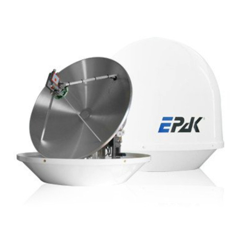
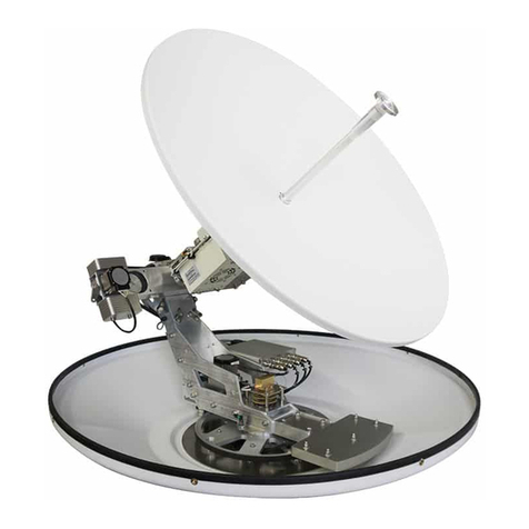
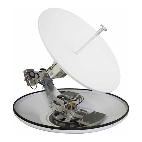
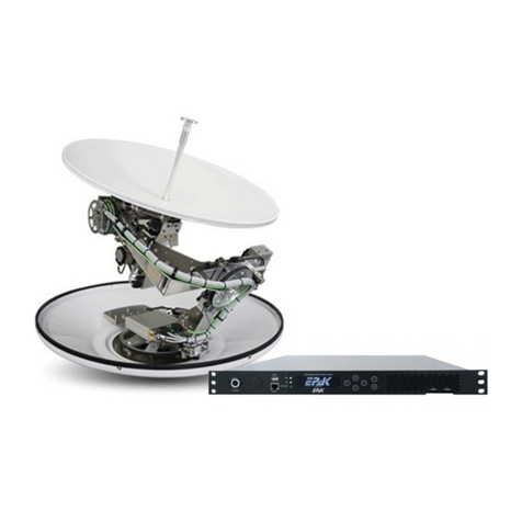
EPAK DSi6 User manual

6DW&RP/LQH'6L'6L

6DW&RP/LQH'6L'6L

Table of Contents
1 The digital satellite tracking system...................................................................................................4
1.1 EPAK®-SatCom s stem overview................................................................................................5
1.2 Safet recommendations................................................................................................................6
2 Installation............................................................................................................................................7
2.1 Standard deliver ............................................................................................................................7
2.2 Installation overview......................................................................................................................7
2.3 Selecting location...........................................................................................................................8
2.4 Mounting surface............................................................................................................................9
2.5 Planning the cable paths.................................................................................................................9
2.6 Power suppl ..................................................................................................................................9
2.7 Drillings..........................................................................................................................................9
2.8 Mounting the antenna unit............................................................................................................12
2.9 S stem cable connections.............................................................................................................12
Control elements.................................................................................................................................14
3.1 ACU..............................................................................................................................................14
3.2 Preparing the network behind the ACU.......................................................................................14
4 Operation............................................................................................................................................15
4.1 Menu tree......................................................................................................................................15
4.2 Preset............................................................................................................................................16
APPENDICES.......................................................................................................................................17
A Maintenance.......................................................................................................................................17
B Troubleshooting.................................................................................................................................18
C Technical specifications....................................................................................................................20
3

'6L
'6L

1.1 EPAK®-SatCom system overview
5
Antenna
Cable types:
RX,TX: double shielded coax cable
(RG6 type) with F-plugs
Ant: 2 x 2,5 ²
AC: Power cords (included)
LAN: Twisted Pair with RJ45 plugs
230V AC ACU
Ant RX TX
Mode
230V AC
LAN
RX TX
LAN
UPS
230V AC
GPS Input via NMEA
provided by ship
LAN
LAN
WAN

1.2 Safety recommendations
➔When mounting the antenna, the distance from the antenna unit to other radiation sources e.g.
radar equipment or other antennas (mobile communication antennas) should be minimum 3 m
(11 ft).
➔Simultaneous operation of radar and satellite antenna ma damage the satellite antenna if not
installed directl above the radar antenna.
➔Do not use the ACU unit outdoors.
➔During a thunderstorm, we recommend that the connection cables are disconnected.
➔If the negative side of the antenna unit’s suppl voltage has no connection to ship’s ground
(earth), then the antenna unit’s ground point should be connected directl to ship’s ground
(earth).
➔After the installation is completed, all other electronic s stems i.e. GPS, Radar, VHF, FM, AM
etc. should be tested for full functionalit , while the antenna is turned on.
➔Do not test or turn on the antenna before the radome is fitted correctl . If the sun reflects into
the dish, the electronics can be damaged.
➔Do not touch the rotar joint.
➔Do not attempt to open the sealed electronics, as this will void the warrant .
➔Do not sta closer than 5m to the antenna during operation
➔It is not allowed to use modem configurations with less than 153,6 kHz Tx Bandwidth
(@ - 3 dB)
6

'6L

2.3 Selecting location
This illustration shows the importance of a proper location for the antenna unit.
Note that criteria such as an unobstructed view to the satellite and a strong mounting surface are met.
Furthermore, no sources of interference, e.g. radar equipment or other antennas, such as mobile
communication antennas, should be installed nearb the antenna unit.
Although the radome is sealed, it is recommended to avoid direct waves and bilge water!
The antenna unit has to be installed so that no superstructures will obstruct the sight to the satellite!
Please note, that the elevation angle depends on the geographical location of the boat and on the
selected satellite!
► Equally important for a good installation are the conditions of the mounting surface and the
lengths of the different cables. See section 2.4, 2.5 and 2.6.
8
Antenna
Antenna
Good view
Bad view
Satellite

2. Mounting surface
A horizontal, solid and stead surface is ver important. Make sure that the surface does not have an
irregularities! Furthermore, please take into consideration that the weight of the antenna unit is 56 kg
or more. Therefore, the surface has to be strong enough to carr the antenna unit, even during the most
challenging maritime conditions.
2.5 Planning the cable paths
Before starting the installation, ou should check which walls are suitable and if existing openings can
be used for the cables.
► All openings have to be sealed in order to avoid any water penetrating.
2.6 Power supply
The antenna unit is powered b the ACU using 24 V DC. The ACU is powered b a built in power
suppl , which is working on 230V AC. Max. power consumption is 150W. The circuit has to be fused
properl .
► The power distributor must be idle while working on the ship’s supply net or you may short
circuit the system.
If the chassis of the antenna unit has no connection to the boat's ground, make sure a potential
compensation between boat ground and the ground point of the antenna unit is made.
2.7 Drillings
To avoid an damage to the mounting surface it is recommended that ou start out with drilling a
smaller hole, using a 3.5-4 mm bit before drilling the correct hole size. Use an 8.5-9 mm bit to drill 4
mounting holes for the M8 screws included. To drill the holes in the correct positions, please refer to
the included template.
9

'6L

'6L

2.8 Mounting the antenna unit
The antenna unit has to be mounted on a solid and stead base parallel to the water surface. Take care
that the cable lengths are sufficient, the antenna unit must have an unobstructed view to the satellite
and there must be no interference fields (especiall mobile communication antennas) nearb .
Place the antenna unit on the pre-drilled holes and fasten it with the included screws and washers. The
screws have to be screwed in from below through the mounting surface into the radome.
► Close all drillings with waterproof sealing material to avoid any water penetrating!
2.9 System cable connections
► Break the contact of the circuit on which you are working to avoid short circuit the system.
●The antenna cables (Power, RX and TX) must be connected to the ACU and the antenna unit.
●The ACU has to be connected to 230VAC 50/60Hz
●The users network is connected to the frontside or backside LAN connector of the ACU
See s stem overview and illustration details.
Lead the cable through the drilled holes and seal it with waterproof sealing material. Furthermore, drip
loops should precede the entr point from the exterior to avoid an water penetrating, see below
illustration:
Find a suitable location for all units within cable lengths. Take care that the displa of the ACU can be
easil read and the push-buttons are accessible. And also, allow room for the cables behind the ACU!
The antenna unit is separated from the power suppl net b the ACU. Therefore, the antenna unit has
electric power when the ACU is turned on!
12
sealing
Cable
Boat
sealing
Cable
Boat
Wrong Correct
Drip loop

Preparing the Power connector:
Housing Insert Chuck Bushing
1. Put bushing and chuck onto the cable.
2. Prepare cable as shown above.
3. Insert the wire into the terminals and fasten the clamping device b a flat screw
driver.
4. Push insert and chuck into housing (pa attention to the guiding ke wa !).
5. Fasten bushing b means of a fork wrench 3/4”, min. Torque 2.5 Nm (1.8 lb-ft).
13
+
—
L
N
power cable
to antenna

3 Control elements
3.1 ACU
The operation of the EPAK-SatCom s stem is controlled from the ACU (19'', 2 HU). It is a good idea
if ou make ourself familiar with the ke functions and the indicators:
Ke s:
POWER : Switches on and off the power for the whole unit
BROWSE : Short press will browse through all available menus, step b step or cancel an
operation.
ENTER : Short press will select/confirm what is written in the displa .
Indicators:
CPU : CPU is running
ODU : Status of power connection to antenna
Green – ODU is powered,
Red – Short or other error,
White – ODU is not connected
BUC : Status of transmit unit (Block Up Converter)
Green - BUC is working
Red - Short or other error,
Blue - BUC is not connected
LOCK: Antenna has locked on correct satellite
LAN : a PC or router is connected to the ACU
WAN : Modem is online
Connectors:
WAN : Connection to the modem
LAN : Connects a PC or router to the ACU
3.2 Preparing the network behind the ACU
On the LAN interface it is possible to configure a DHCP server or static IP addresses. To connect
more then one PC, ou can use a simple Switch (a Router is included in the ACU).
14
Power
Service ENTER
BROWSE
LAN 1 LAN 2
ODU BUC CPU LOCK LAN WAN
Mode
Antenna
RX TX
LAN 3 WAN ANT
AC POWER
230V 50 Hz

4 Operation
.1 Menu tree
* Check for an obstacles in the free sight line to the satellite.
** needed for adaption on local circumstances
*** Can be skipped b pressing ENTER, last saved GPS position will be used.
15
Preset
serial no.
counter
operation ti e
software version
antenna unit
software version
control unit
Init
complete
Wait GPS
scanning
Satellite
Enter
XXXXXXX
T XXXX
VA X-XX
VC X-XX
Browse
Browse
Browse
Browse Preset? Enter
Browse
complete
Using old data set
Choice of satellite
Co pass calibration
Search for satellite
Success?
(LOCK on)
NO
YES
Keep
pressing
ON/OFF
scanning
complete
Enter
Satellite
*
**
Preset
checking
***
updating
calibrat
checking
complete
scanning
Co pass is calibrating
Search?
Satellite 1
Satellite 2
Satellite 3
...
Enter
Browse
Enter
Keep pressing
Compass
ff
Enter Browse
scanning
Co pass is used
Co pass is not used

States:
Init The antenna is in initialization phase and checks the limit switches and motors
Wait GPS
The antenna waits for valid GPS data from the built in GPS receiver. If no GPS is
received or the GPS module is defective, the antenna will hang in this state
forever!
calibrate Antenna is calibrating the internal compass.
scanning
Satellite Antenna searches for satellite.
Satellite Antenna has found the satellite and tracks it.
When the satellite has been found and identified correctl , the indicator LOCK will be lit. The
indicator LAN is on, when a PC or router is connected on the LAN port of the. When the modem has
connected to the internet, the WAN indicator is on.
.2 Preset
In the first time installation a preset has to be done. This means, after power on and after the message
complete, press BROWSE (displa Preset?) and then ENTER. Then a list of preprogrammed
satellites is shown, which can be browsed b pressing the BROWSE button. B pressing ENTER the
actual shown satellite will be selected. B pressing ENTER the compass will be calibrated
(calibrat is shown in the displa ). In order to deactivate the compass (which is likel needed on
steel ships and/or a steel made mounting platform), press the ENTER button for a long time as soon as
the displa shows scanning. After 4 seconds Compass / Off is shown and b pressing
ENTER the compass will be switched off. B pressing BROWSE the compass will be used. Now the
satellite will be searched (scanning/Satellite in the displa ) and stored if found.
This step can take a few minutes.
16

APPEND CES
A Maintenance
The satellite tracking s stem EPAK-SatCom does not require a lot of maintenance. The following
instructions are sufficient to sustain the optimal capacit of the antenna unit:
•Clean the radome once a month, using fresh water and a mild detergent to remove dirt and salt
deposits.
•Do not detach the radome!
•Do not spra directl on the radome with high pressure water from a hose!
•Check cable connections to be tight and free of corrosion. Clean the cables regularl .
The radome has a protective la er of UV-stabilized and maritime climate-proof lacquer. Do not appl
an additional paint, wax, preservative, solvent, chemicals or adhesive labels. An kind of coating will
void warrant claims!
In case an solvent comes in contact with the radome b accident, rinse the area immediatel with
water and, if necessar , with a mild detergent!
17

B Troubleshooting
Display Problem Remedy
no dish
No connection to the antenna unit - Check cable connection to antenna unit (power and
antenna cable)
- Check antenna unit’s power suppl
ErrorCom
Communication error with antenna
unit
Turn unit off and on again
Low Vsup
Power suppl for antenna too low - Check power suppl connection for antenna unit (loose
cables/connectors or wrong cable t pe)
Err R
Read error of horizontal unit
Err W
Write error of horizontal unit
Err VR
Read error of vertical unit
Err VW
Write error of vertical unit
Err SR
Read error of signal processing unit
Err SW
Write error of signal processing unit
Err PR Read error of polarisation unit
Err PW Write error of polarisation unit
Err VCO
Error during satellite inspection
Err EEP
Error during storage
Err IIC
Error in internal communication
Err Trck
Error in tracking module
Err ULS
Error in upper limit switch
Err LLS
Error in lower limit switch
Err ELS Error in eastern limit switch
Err WLS Error in western limit switch
Turn the unit off and on again. In case the error reoccurs,
call for technical assistance.
In case of errors regarding limit switches:
Check all moving parts for nonblocking functionalit
Err Comp
Compass error Compass will automaticall reset and recallibrate. After
that, please do a preset. In case the error reoccurs several
times, call for technical assistance.
Err Save
Error while saving satellite Repeat search and storing procedure. Make sure the boat
is not moving and no superstructures obstruct the sight to
the satellite
complete
The search for a stored satellite was
successful, but no picture is shown
- Delete satellite storage positions and memorize again
Wait GPS Antenne is waiting for valid GPS
data.
- GPS signal is jammed b another signal source
- GPS receiver is defective
Sat
X
interchanging with
no Sig
No reception of the stored satellite - Check if superstructures (e.g. steeple cab or masts of
proximate boats) obstruct the sight to the satellite − if so,
move the boat
- Reception can be briefl interrupted b passing boats
scanning
interchanging with
complete
No receptable satellite in the entire
search range
- Check, if an superstructures are obstructing the sight to
the satellite
- Check, b using footprint cards (e.g. www.satcodx.com),
that the boat is inside the coverage area (footprint)
>Short!<
There is a short in the connection
between and antenna
Check cable connection to antenna and rotar joint inside
of antenna
18

Cannot find a satellite - Check, if superstructures obstruct the view to the
satellite
Search for stored satellite takes
longer, even though there are no
obstructions in the view to the
satellite
If the location of the vessel changes, the angles of the
satellite ma have changed. Modif angles of the satellite
at the new location with the function
Preset
, see
section 4.
Preset?
Antenna asks for confirmation to
update the satellite data
Standby
–Antenna could not find a satellite
for 15 minutes.
–There was the error message no
dish before.
Press ON/OFF, if ou have free sight to the satellite, the
antenna should find it again.
upd reco
saved satellite data is not completel
similar to the real data measured b
the antenna
Do a preset, like described on page 15.
19

DSi6 DSi9
This manual suits for next models
1
Table of contents
Other EPAK Antenna manuals
Popular Antenna manuals by other brands
Chameleon Antenna
Chameleon Antenna CHA TD 2.0 Operator's manual
Siemens
Siemens SIMATIC NET ANT795-6MT Compact operating instructions
Altelix
Altelix AU5158G12 installation instructions
Directive Systems & Engineering
Directive Systems & Engineering DSE1209LYRM quick start guide
SEESTATION
SEESTATION SS-MES-CPE user manual
HP
HP J9659A Guide
