manuals.online logo
Brands
  1. Home
  2. •
  3. Brands
  4. •
  5. Epever
  6. •
  7. Inverter
  8. •
  9. Epever IP350-11 User manual

Epever IP350-11 User manual

BEIJING EPSOLAR TECHNOLOGY CO., LTD. Tel:+86-10-82894112 / 82894962 Website:www.epsolarpv.com/www.epever.com
1 2
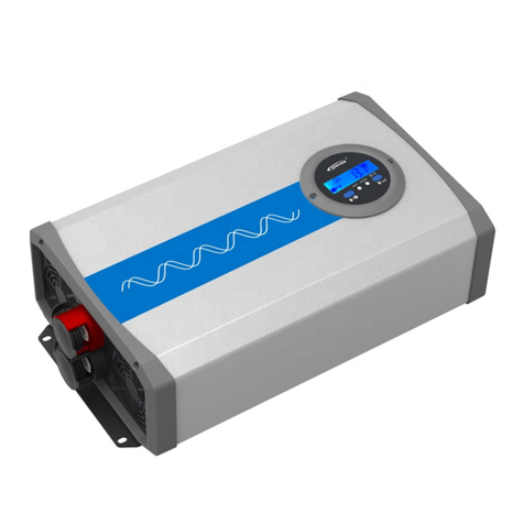
IPower series Pure Sine Wave Inverter
1. Overview
IPower series is a pure sine wave inverter which can convert 12/24Vdc into
110/120Vac. It has the characteristics of concise outline, compact size, high
reliability, high efficiency, easy to install and operate and so on. The inverter
applicable to household emergency lighting system, vehicle mounted
system and small field power supply, etc.
Features:
Complete isolation-type inverter technology
Adoption of advanced SPWM technology, pure sine wave output
Low output harmonic distortion (THD≤5%)
Optional output voltage and frequency at 110/120Vac,50/60Hz
High conversion efficiency up to 91%
USB output 5Vdc/1A
Extensive Electronic protection
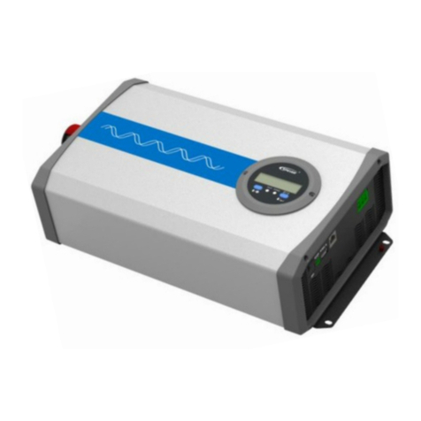
2. Product Features
①
DC positive input
⑥
Fault indicator(red)
②
Fuse
⑦
Working indicator(green)
③
Fan Ventilation
⑧
USB output interface(5VDC/1A)
④
DC negative input
⑨
AC Outlet
⑤
AC output switch
⑩
Mode switch
NOTE:12V system input voltage range is 10.8~16V; 24V
system input voltage range is 21.6~32V.
1) Fan Ventilation
When the heat sink temperature is more than 40℃or internal temperature
is more than 45℃, the fan will turn on automatically.
When the heat sink temperature is lower than 35℃and internal
temperature is lower than 40℃, the fan will turn off automatically.
2) Mode Switch
The output mode can be changed by the mode switch. This mode can be
switched online.
When the switch No.1 is on the ON side, output frequency is 60Hz,
otherwise is 50Hz.
When the switch No.2 is on the ON side, the output voltage is 120Vac,
otherwise is 110Vac.
NOTE: Both the output frequency and the output voltage
change availability after restart the inverter.
WARNING:DO NOT turn ON/OFF the mode switch when the
inverter is working.
3) LED indicator and Buzzer
Working indicator
Fault indicator
Buzzer
Status
Green On Solid
Red OFF
No Sounding
Output is ON
Green Slowly
Flashing
Red OFF
Sounding
Input low voltage
Green Fast
Flashing
Red OFF
Sounding
Input over voltage
Green On Solid
Red On Solid
Sounding
Over temperature
Green OFF
Red Fast
Flashing
Sounding
Load short circuit
Green On Solid
Red Slowly
Flashing
Sounding
Overload
Green OFF
Red OFF
Sounding
Output voltage
abnormal
4) AC Outlet (optional)
Universal:
Australia/New Zealand:
European:
3. Installation and wiring
1)Notes of installation
Do not expose the inverter to humid, flammable, explosive or dust
environment.
Please make sure the air ventilation clearance around the inverter is
more than 10cm.
Never install the inverter in a sealed enclosure with flooded batteries.
Figure1 DC Input panel
Figure2 Output panel
※Thank you for selecting the IPower series Pure Sine Wave Inverter.
Please read this manual carefully before using the product and pay
attention to the safety information.
BEIJING EPSOLAR TECHNOLOGY CO., LTD. Tel:+86-10-82894112 / 82894962 Website:www.epsolarpv.com/www.epever.com
3 4
The surface of the inverter produce high temperature when it is working,
please stay away from materials or equipment which affected by high
temperature
This inverter can only be used singly, parallel connection or in series will
damage the inverters.
It’s an off-grid inverter, if connect to the grid, the inverter may be
damaged.
2)Wiring
NOTE: If the output is connected different loads, it is suggested
that turn on the large shock current load first, then turn on the
small shock current load.
NOTE:Turn off the inverter, and then cut off the DC input power
supply when the load stops working.
WARNING:When the inverter polarity reversed, the fuse or
inverter will be damaged.
WARNING:Be careful the electric shock risk, the AC port will
output a high voltage.
WARNING:DO NOT open the inverter cover, place where the
children can't reach to prevent electric shock.
WARNING:Please contact the professional, when the inverter
occur the faults
4.Protection
Protection
and recover
Condition
Phenomenon
Parameter
IPower-11
IPower-21
Over voltage
protection
and recover
Input
Voltage Ui
Ui>16V±3%
Ui>32V±2%
Output is OFF
Green indicator fast flashing
Buzzer sounds
Ui≤14.5V±3%
Ui≤29V±2%
Green indicator on solid
The output is on
Low voltage
protection
and recover
Input
Voltage Ui
Ui<10.8V±3%
Ui<21.6V±2%
Output is OFF
Green indicator slowly flashing
Buzzer sounds
Ui≥12.5V±3%
Ui≥25V±2%
Green indicator on solid
The output is on
Over tem.
protection
and recover
Tem.(T)
Heat sink T≥75℃
(IP350-12:70℃)
or Internal T≥65℃
Inverter turn OFF
Heat sink T≤55℃
and Internal T≤50℃
Inverter turn ON
Overload
protection①
and recover
Output
power S
Output
power Pe
S=1.2Pe
Output is OFF after 15min
Red indicator slowly flashing
Buzzer sounds
S=1.3Pe
Output is OFF after 1min
Red indicator slowly flashing
Buzzer sounds
S=1.5Pe
Output is OFF after 10s
Red indicator slowly flashing
Buzzer sounds
S>2Pe(Rated input power)
Output is OFF after 5s
Red indicator slowly flashing
Buzzer sounds
Load short circuit protection①
Output is OFF immediately
Red indicator fast flashing
Buzzer sounds
①When appear output overload protection or load short circuit protection, it has
three times auto-recover output function (once delay 5s, twice delay 10s and three
times delay 15s).
5. Troubleshooting
Faults
Possible reasons
Troubleshooting
Green indicator
slowly flashing
Buzzer sounds
DC input voltage too
low
Measure the DC input voltage, if the
voltage is lower than 10.8V/21.6V. Adjust
the input voltage to restore normally.
Green indicator
fast flashing
Buzzer sounds
DC input voltage too
high
Measure the DC input voltage, if the
voltage is higher than 16V/32V. Adjust
the input voltage to restore normally.
Red indicator
slowly flashing
Buzzer sounds
Overload
①Reduce the number of the AC load.
②Restart the inverter.
Red indicator
fast flashing
Buzzer sounds
Short circuit
①Check carefully loads connection,
clear the fault.
②Restart the inverter.
Green and red
indicator on solid
Buzzer sounds
Over temperature
When the heat sink temperature exceeds
75℃or the internal temperature exceeds
65℃, the inverter will automatically stop
output; When the heat sink temperature
below 55℃and the internal temperature
below 50℃, the inverter will resume to
output.
6.Technical Specifications
Technical Parameters
Model
Item
IP350-11
IP500-11
IP350-21
IP500-21
Input Rated Voltage
12VDC
24VDC
Input Voltage Range
10.8~16VDC
21.6~32VDC
Input surge voltage
<32V
<44V
Fuse
32VDC/50A
2*32VDC/35A
32VDC/30A
2*32VDC/25A
No-load current
<0.7A
<0.9A
<0.5A
<0.5A
Output Voltage
110VAC(±5%)
120VAC(-10%~+5%)
Output Continuous
Power(-20℃~+45℃)
350VA
500VA
350VA
500VA
Power factor
0.8
Instantaneous impact
power
≥750VA
≥1000VA
≥750VA
≥1000VA
Output way
Single phase
Output Wave
Pure sine wave
Output Frequency
50/60Hz(±0.2%)
Distortion THD
THD≤5%(Resistive load)
Max. Efficiency
91%
90%(IP350-11)
Max. USB Output
5VDC/1A
Environmental Parameters
Working environment
temperature
-20℃~+45℃
Storage temperature
range
-35℃~+70℃
Humidity range
≤93%(N.C.)
Enclosure
IP20
Altitude
<2000m
(Derating to operate according to IEC62040 at a
height exceeding 1000 m)
Mechanical Parameters
Model
IP350-11
IP350-21
IP500-11
IP500-21
DC input terminal
6mm2
Overall dimension
214×105.5×57.7mm
232.2×132×74.5mm
Mounting dimension
185.5×76.7mm
205×102mm
Mounting hole size
Φ4.2mm
Φ5.2mm
Net weight
0.9kg
1.4kg
7. Disclaimer
This warranty does not apply under the following conditions:
Damage from improper use or use in an unsuitable environment.
Battery voltage exceeding the rated value of inverter.
User disassembly or attempted repair the inverter without permission.
The inverter is damaged due to natural elements such as lightning.
The inverter is damaged during transportation and shipment.
Any changes without prior notice! Version number:V1.0
Figure 1 DC Input
Figure 2 Output
Operation Steps:
Step1: Turn off the inverter.
Step2: Connect the AC load to the AC outlet.
Step3: Connect the battery.
Step4: Turn on the inverter.
Step5: Turn on theAC load.
This manual suits for next models

4

Other Epever Inverter manuals

Epever UP1500-M3222 User manual

Epever

Epever UP1500-M3222 User manual

Epever VS1024AU User manual

Epever

Epever VS1024AU User manual

Epever LS EPD Series User manual

Epever

Epever LS EPD Series User manual

Epever LS0512E User manual

Epever

Epever LS0512E User manual

Epever IP1500-11 User manual

Epever

Epever IP1500-11 User manual

Epever IPower Series User manual

Epever

Epever IPower Series User manual

Epever TP10K User manual

Epever

Epever TP10K User manual

Epever UP2000-HM6021 User manual

Epever

Epever UP2000-HM6021 User manual

Epever IP350-12 User manual

Epever

Epever IP350-12 User manual

Epever UP1000 User manual

Epever

Epever UP1000 User manual

Epever HP3542-AH0650P20SA User manual

Epever

Epever HP3542-AH0650P20SA User manual

Epever UPower Series User manual

Epever

Epever UPower Series User manual

Epever LS-EPD Series User manual

Epever

Epever LS-EPD Series User manual

Epever NPower Series User manual

Epever

Epever NPower Series User manual

Epever IP500-Plus User manual

Epever

Epever IP500-Plus User manual

Epever NPower Series User manual

Epever

Epever NPower Series User manual

Epever IP1500-Plus Series User manual

Epever

Epever IP1500-Plus Series User manual

Epever IP350-12 User manual

Epever

Epever IP350-12 User manual

Epever TPower Series User manual

Epever

Epever TPower Series User manual

Epever UPower Series User manual

Epever

Epever UPower Series User manual

Epever Tracer 2210CN User manual

Epever

Epever Tracer 2210CN User manual

Epever NP260 User manual

Epever

Epever NP260 User manual

Epever LD150S-N1 User manual

Epever

Epever LD150S-N1 User manual

Epever IP1000-Plus User manual

Epever

Epever IP1000-Plus User manual

Popular Inverter manuals by other brands

Phocos SI700-12110 user manual

Phocos

Phocos SI700-12110 user manual

Hisense AS-07UR4SYDDB15 Service manual

Hisense

Hisense AS-07UR4SYDDB15 Service manual

TECO JN5-CM-USB instruction manual

TECO

TECO JN5-CM-USB instruction manual

Allen-Bradley PowerFlex 700H installation instructions

Allen-Bradley

Allen-Bradley PowerFlex 700H installation instructions

Hyundai Electric N800 Series installation manual

Hyundai Electric

Hyundai Electric N800 Series installation manual

VOLTWORKS VK300S user manual

VOLTWORKS

VOLTWORKS VK300S user manual

Phocos ECO-N-MPPT 85/15 user manual

Phocos

Phocos ECO-N-MPPT 85/15 user manual

Toshiba TOSVERT VF-S9 instruction manual

Toshiba

Toshiba TOSVERT VF-S9 instruction manual

Mitsubishi Electric FR-A7ND E kit instruction manual

Mitsubishi Electric

Mitsubishi Electric FR-A7ND E kit instruction manual

Mitsubishi FR - S500 instruction manual

Mitsubishi

Mitsubishi FR - S500 instruction manual

Shindaiwa dga20e Owner's and operator's manual

Shindaiwa

Shindaiwa dga20e Owner's and operator's manual

PEGAS 200 AC-DC Service manual

PEGAS

PEGAS 200 AC-DC Service manual

Mitsubishi Electric F700 instruction manual

Mitsubishi Electric

Mitsubishi Electric F700 instruction manual

Sunforce 44445 manual&nbsp;

Sunforce

Sunforce 44445 manual&nbsp;

Victron energy MultiPlus Compact 12/2000/80-30 230V manual

Victron energy

Victron energy MultiPlus Compact 12/2000/80-30 230V manual

INFOSEC C3 MPPT user guide

INFOSEC

INFOSEC C3 MPPT user guide

Sungrow SG100KU installation manual

Sungrow

Sungrow SG100KU installation manual

Maxeon SunPower Reserve Quick installation guide

Maxeon

Maxeon SunPower Reserve Quick installation guide

manuals.online logo
manuals.online logoBrands
  • About & Mission
  • Contact us
  • Privacy Policy
  • Terms and Conditions

Copyright 2025 Manuals.Online. All Rights Reserved.