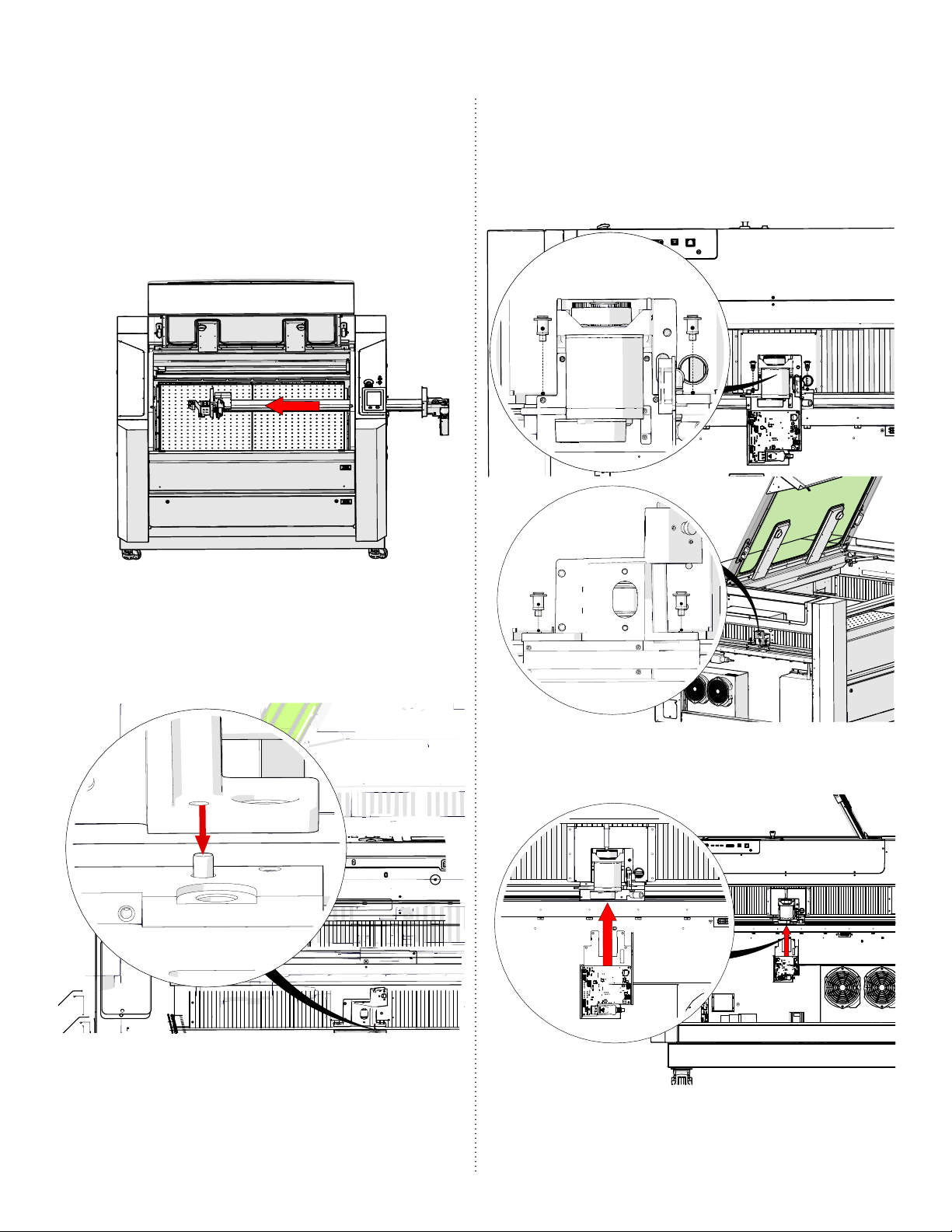
PRO 32 & 48 X-AXIS ASSEMBLY
10
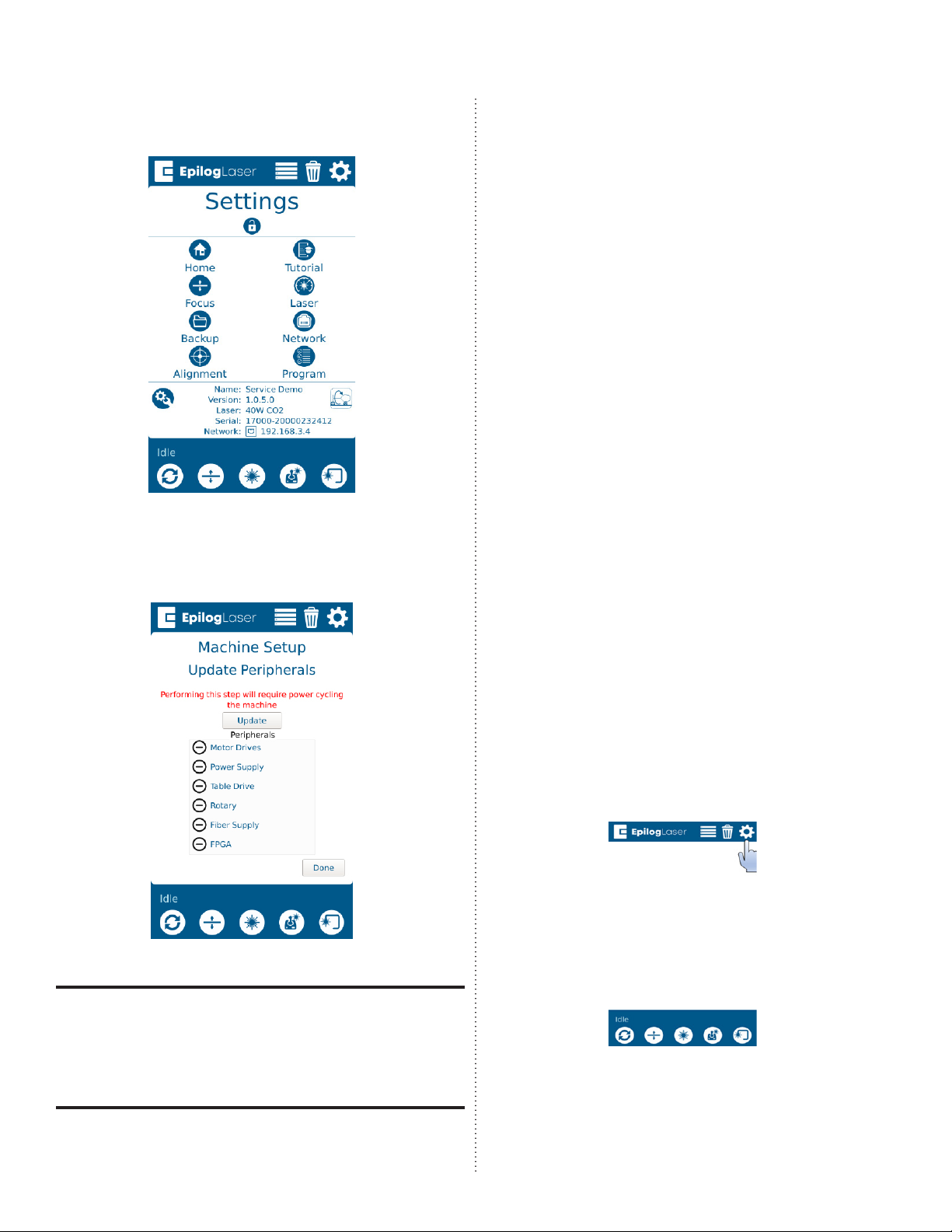
2. Once in the Settings menu, press
the Focus button to enter the Focus
Commands/Calibrations menu:
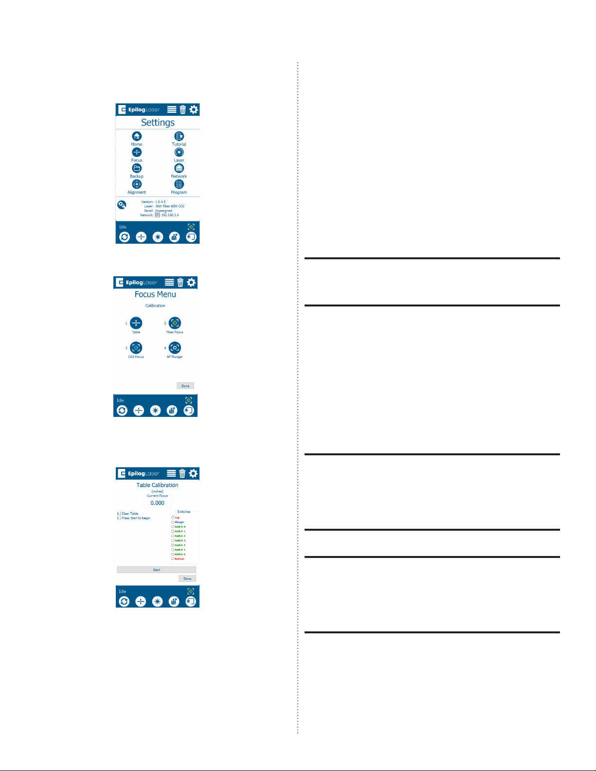
3. Press the Table button:
4. Press the Start button to start the table
calibration:
4. Allow the engraver to complete the
calibration. Once complete, a success
message should appear.
Move to the CO2 Focus Procedure.
CO2 Focus Calibration
The CO2 focus calibration establishes
the focal height of the laser and manual
focus gauge. You will run a small job while
adjusting the table height to find the
correct focal height.
A small piece of anodized aluminum (at
least 3” x 3” or 75mm x 75mm) is required to
complete this procedure.
1. Open your preferred illustrating
program and create a black, raster box
measuring ~2” x 2” or 50mm x 50mm.
2. Send the job to the Soware Suite.
3. Ensure that the process shows as an
engraving job and set the both power
and speed at 5-10%.
If completing the procedure on the Fusion
Pro 32, place the artwork and material
in the upper le corner of the engraving
table, ensuring that the artwork appears
over the anodized aluminum.
If completing the procedure on the Fusion
Pro 48, place the artwork and material in
the center of the engraving table, ensuring
that the artwork appears over the anod-
ized aluminum.
4. Send the job to the engraver.