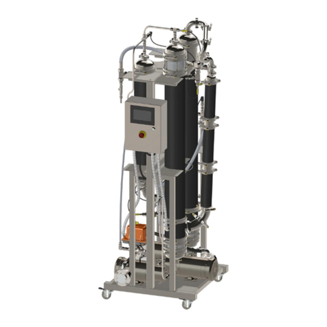
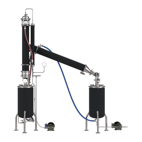
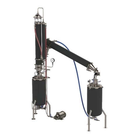
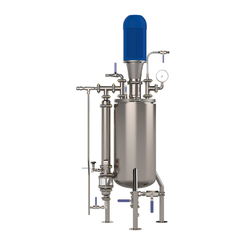
TruSteel AutoVap30 User manual

Copyright © 2020 byTruSteel LLC. All Rights Reserved.
TruSteel AutoVap30 User Manual
Version: 1.9

TruSteelAutoVap30 User Manual | |v. 1.9
2 / 39
Table of contents
SECTION I: AUTOVAP OPERATING PRINCIPLE .................................................... 4
SECTIONII: AUTOVAP30 SYSTEM EQUIPMENT .................................................... 4
SYSTEM REQUIREMENTS ............................................................................... 8
SECTION III: STARTUP PROCEDURES ................................................................ 8
CHILLER STARTUP ........................................................................................ 8
WATER HEATER STARTUP ............................................................................. 8
VACUUM PUMP STARTUP .............................................................................. 9
SECTION IV: OPERATING PROCEDURES ............................................................. 9
POWER ON SYSTEM ...................................................................................... 9
VERIFY PARAMETERS .................................................................................. 11
PRIME FEED PUMP ....................................................................................... 13
PUMP CONTROLS ........................................................................................ 15
AUTO RECOVERY MODE .............................................................................. 19
SECTION V: RECYCLE MODE ............................................................................ 20
SECTION VI: CLEAN MODE .............................................................................. 21
CLEANING CYCLE PREPARATION ................................................................. 22
STAGE 1: SOLVENT CLEANING CYCLE .......................................................... 22
STAGE 2: DISTILLED WATER CLEANING CYCLE ............................................. 23
STAGE 3: SOLVENT CLEANING CYCLE 2 ....................................................... 24
STAGE 4: COMPLETING CLEAN MODE ........................................................... 24
SECTION VII: SHUT DOWN .............................................................................. 24
SECTION VIII: OPERATION AND SAFETY INFORMATION ................................... 25
HMI OPERATION ......................................................................................... 26
PUMP CONTROL ...................................................................................... 26
SYSTEM MODES .................................................................................. 26
PUMP STATUS ..................................................................................... 27
MANUAL OVERRIDE ............................................................................. 28
FEED PUMP LOCKOUTS ........................................................................ 28
FEED PUMP AUTO SP ........................................................................... 28
TEMPERATURE ........................................................................................ 28
ALARMS .................................................................................................. 29
ALARM RESET ......................................................................................... 31
MAINTENANCE ............................................................................................ 31
ETHYL ALCOHOL SAFETY INFORAMTION – MSDS .......................................... 32
FIRST AID MEASURES .................................................................................. 32
TROUBLESHOOTING ........................................................................................ 33
APPENDIX ....................................................................................................... 34
VACUUM/ELEVATION CHART ....................................................................... 34
AV30 FLOW DIAGRAM ................................................................................. 35
AV30 QUICKSTART MANUAL ............................................................................ 38
STEP 1: ANCILLARY STARTUP ..................................................................... 38
STEP 2: POWER ON SYSTEM ........................................................................ 38
STEP 3: PRIME FEED PUMP ........................................................................... 38
STEP 4: EXTRACTION MODE ........................................................................ 38
STEP 5: DISCHARGE FIRST CRUDE ............................................................... 38
STEP 6: RECYCLE MODE .............................................................................. 38
STEP 7: CLEANING CYCLE ............................................................................ 39

TruSteelAutoVap30 User Manual | |v. 1.9
4 / 39
SECTION I: AUTOVAP OPERATING PRINCIPLE
How the AutoVap30 Falling Film Evaporator Works:
TheAutoVap30 Falling Film Evaporator is designed to recover at least 30 gallons of saturated
solvent while recovering over 95% solvent. TheAutoVap30 system works by moving saturated
solvent through a heated exchange path where the solvent is evaporated from the desired
“crude” material. TheAutoVap30 separately discharges the crude material and recovered
solvent.
TheAutoVap30 utilizes an on-board touch screen control panel that full automates the recovery
process which includes fail safes, alarms, and datalogging. Parameters are set in place upon
installation of theAutoVap30 system making operation very user friendly and non-technical.
It is important to note that theAutoVap30 through puts are based on the ancillary equipment
supplied by TruSteel. This includes the cooling unit, water heating system, and vacuum pump.
The on-board control panel is required to properly operate the system. Any changes in
equipment specifications or placement of equipment out of the scope of TruSteelʼs Pre-
Installation Manual may causes losses in efficiency of recovery.
Upon installation of theAutoVap30, TruSteel will train the staff who will be operating the system.
This operating manual can also be used as a guide.
SECTIONII: AUTOVAP30 SYSTEM EQUIPMENT
Materials Stainless Steel, PTFE, & Borosilicate
Throughput 30+ gallons per hour
Plumbing Connections 1”
Compatible With: Ethanol, Methanol, Heptane, Hexane, Acetone,
Acetonitrile
TheAutoVap30 system requires ancillary equipment to work with theAutoVap30 machine. The
main components to the system are:
1) TheAutoVap30, including (3) main heat exchangers [1 preheater, 1 evaporator, 1 condenser],
(3) pumps [feed pump, solvent discharge, crude discharge] and (1) HMI panel
2) Cooling System – an HVAC chiller unit
3) Heating System – Recirculating Hot Water Heater
4) Vacuum Pump
5) PLC Control Panel – Power supply controller for HMI
6) Heater Manifold which includes an inline water pump to recirculate water
7) Chiller bypass manifold

TruSteelAutoVap30 User Manual | |v. 1.9
5 / 39

TruSteelAutoVap30 User Manual | |v. 1.9
6 / 39

TruSteelAutoVap30 User Manual | |v. 1.9
7 / 39

TruSteelAutoVap30 User Manual | |v. 1.9
8 / 39
SYSTEM REQUIREMENTS
WATER HEATING (Gas or Electric)
Electric Water Heater minimum 33-36kw; minimum 10 gpm flow
rate; distilled water with 10% glycol
(suggested); 1" plumbing
Gas Water Heater 300 BTU; minimum 10 gpm flow rate; distilled
water with 10% glycol (suggested); 1"
plumbing
COOLING minimum 10 tons of cooling; 1" plumbing
VACUUM suggested: 6.1 cfm / 174 L/min
SECTION III: STARTUP PROCEDURES
In order to operate theAutoVap30 at correct capacity, the system requires the ancillary
equipment to be turned on and set at the correct parameters.
Operators shall follow the following procedures and verify all equipment is functioning properly
before proceeding to the next steps of operation.
CHILLER STARTUP
Please refer to the user manual of your chiller system for guidance of operation.
The suggested operating temperature of your chiller system is 41-44°F (5-7°C)
WATER HEATER STARTUP
Please refer to the user manual of your water heater system for guidance of operation.
Note: MostAutoVap30 water heater systems have a manifold with a recirculating water pump.
Powering on this recirculating water pump will provide flow to the water heater and trigger the
water heater to heat the water.
Ideal Parameters:
Water Heater Setpoint: 185-194°F (85-90°C)
Note: This is an ideal setpoint if you are recovering ethanol. Other solvents may have a
lower temperature setpoint. (ie, hexane)
Note: Gas water heaters tend to operate better at a setpoint no higher than 186°F (85.5°
C)
Recirculating Water Pump: The system should be able to maintain a flow rate of at least 10
gallons per minute.

TruSteelAutoVap30 User Manual | |v. 1.9
9 / 39
Note: If the flow rate has dropped to below 10 gpm, you may need to re-prime the water
heater system. (SeeAutoVap30 Pre-Installation Manual)
Pro Tip
CHECK WATER HEATER DIAGNOSTICS (Electric Heater Models Only)
This is an important step to check each day of operation to be sure the flow is high enough.
Press and Hold both the UP and DOWN arrows simultaneously for 1-2 seconds and release.
You should not be in diagnostic mode.
Numbers will begin “flashing” on the water heater screen.
1st number is the heater temperature setpoint
2nd number is the temperature “OUT” of the heater to theAutoVap
3rd number is the temperature “IN”, back from theAutoVap
4th number is the “Flow Rate” in gallons/minute
The Flow Rate is very important
You must have a flow rate above 10 gallons/minute.
If the flow rate is below that, theAutoVap may not operate efficiently.
The flow rate should be between 10-18 GPM for optimal operation.
If the flow rate is below 10 gallon per minute you must refill the heater with water. Do this when
the before the heater is turned on. You must refill the heating system while the system cold.
VACUUM PUMP STARTUP
Please refer to the user manual of your chiller system for guidance of operation.
#VERIFY VACUUM
You can verify the system is pulling vacuum from theAutoVap itself.
Open the vacuum valve on the vacuum manifold on theAutoVap. Open the vacuum fine tune
adjustment. There should be vacuum flow.
SECTION IV: OPERATING PROCEDURES
POWER ON SYSTEM
POWER ON THE AUTOVAP 30 SOLVENT RECOVERY SYSTEM
1. POWER ON PLC
Turn the Main Disconnect to the “ON” position

TruSteelAutoVap30 User Manual | |v. 1.9
10 / 39
Pull the Red EMERGENCY button “OUT”
Turn all H.O.Aswitches to “AUTO”

TruSteelAutoVap30 User Manual | |v. 1.9
11 / 39
2. POWER ON HMI (Human Machine Interface/Touch Screen)
Pull out RED EMERGENCY button
In about 15 seconds, the “HOME SCREEN” will appear and will begin to monitor pump control,
temperature, and alarm settings.
VERIFY PARAMETERS
On the HMIHome Screen, first verify the VACUUMlevel has "dropped" to within your working
parameter (1.2-2.0 PSIA)

TruSteelAutoVap30 User Manual | |v. 1.9
12 / 39
Then Press "TEMPERATURE" button.
Note: It may take 5-10 minutes for all temperatures to reach maximum range after powering on
ancillary equipment.
Verify the PRE-HEATER OUTLET, EVAP INLET, EVAP OUTLET are all registering "hot"
temperatures.
Verify the COND INLET, COND OUTLET are registering "cold" temperatures.

TruSteelAutoVap30 User Manual | |v. 1.9
13 / 39
PRIME FEED PUMP
PRIME FEED PUMP USING VACUUM
This step is critical as it will save your feed pump from running dry. Follow this step every time
you begin to feed tincture into the system before runningAuto Mode.
Note: This step is only necessary if there is no liquid in the sight glass just below the preheater.
Procedures
1. Return to the HOME SCREEN [button in top left corner of HMI]
2. Open Vacuum Ball Valve
Open the Blue Ball Valve located on the vacuum line
This will introduce vacuum into theAutoVap system (as long as the Vacuum pump is on)

TruSteelAutoVap30 User Manual | |v. 1.9
14 / 39
3. Adjust vacuum pressure to 1.2-2.0 PSIA (pounds per square inch absolute)
The black needle valve located on the vacuum manifold is your fine adjust for vacuum
By turning the needle valve clockwise, you will be increasing vacuum on the system
By turning the needle valve counterclockwise, you will be releasing vacuum on the system
4. Verify Vacuum Pressure (1.2-2.0 PSIA)
Locate Vacuum Pressure on the HMI Home Screen and verify the “VACUUM” is in range
(1.2-2.0 PSIA)
5. Open Feed Line Ball Valve
Locate your feed line ball valve and open it. The vacuum pressure will draw material from
the feed line, through the pump(priming it), and into the system.
Once there is liquid in the sight glass below the preheater, the AutoVap can be started.

TruSteelAutoVap30 User Manual | |v. 1.9
15 / 39
PUMP CONTROLS
STEP 1: SET PUMP LOCKOUT SETPOINTS
In this section you will be able to change and set your parameters for your lockouts. If the system
is running within range of your parameters, then it will continue to run until you manually stop the
system. If a parameter goes out of the setpoint range, the feed pump will automatically stop.
Procedures
1. Open the PUMP CONTROL Screen
Locate PUMP CONTROL on the HMI Home Screen and press on the button to open
the PUMP CONTROL Screen.

TruSteelAutoVap30 User Manual | |v. 1.9
16 / 39
2. Understanding the Pump Control Screen
LOCKOUTS are located in the FEED PUMP section (to the left)

TruSteelAutoVap30 User Manual | |v. 1.9
17 / 39
All LOCKOUT lights must be GREEN to start to the AutoVap
Each LOCKOUT corresponds to a specific piece of ancillary equipment

TruSteelAutoVap30 User Manual | |v. 1.9
18 / 39
VAC PSI = Vacuum Pump
If the vacuum pressure on the system "drops" to 10 PSI, the system will stop (lockout)
EVAP INLET = Water Heater
If the evaporator column senses the water heater temperature below 175°F (~79°C), the
system will stop (lockout)
This most likely means there is an issue with the water heater and it needs to be
addressed.
COND INLET = Chiller
If the condenser column senses the temperature above 55°F (~12°C), the system will
stop (lockout)
This most likely means there is an issue with the chiller and it needs to be addressed.
If one of these Lockouts are red, please verify whether the corresponding piece of equipment is
operating properly.

TruSteelAutoVap30 User Manual | |v. 1.9
19 / 39
3. Check and Adjust Lockout Setpoints (if necessary)
Press on the lockout number you would like to adjust
Some common setpoints (setpoints may vary depending on your material and your
custom procedure)
Vacuum PSI Setpoint: 8-10 PSI
EVAP Inlet Setpoint: 150-175°F
Condenser Inlet: 46-55°F
AUTO RECOVERY MODE
Now that all set points and lockouts are in range (See ranges in PUMP CONTROL). TheAV-30 is
ready to operate.
START FEED PUMP
Procedure
1. Verify SYSTEMMODE says "EXTRACTION MODE" (far left, lower side of HMIHome
Screen)
2. Locate the FEED PUMP area on the HMI Home Screen.
3. Press and Hold the START button for 1-2 seconds
4. You should see a countdown timer which will remind you to Open the Feed Valve
5. The Feed Pump will slowly “ramp” up to 35 PSI (may take 3-4 minutes)
Note: The PSI will spike above 35 PSI for a moment and then will slowly decline back
down to 35 PSI. The spike is due to pressure trapped in the system.
6. TheAutoVap PSI can be adjusted up or down to the desired setpoint from the PUMP
CONTROLpage.

TruSteelAutoVap30 User Manual | |v. 1.9
20 / 39
Go to PUMP CONTROLscreen. Locate FEED PUMP section. LocateAUTO
SETPOINTS >PSI SETPOINT. Press on the PSISETPOINT number and enter in your desired
PSISETPOINT.
Normal operating PSI is between 30-60 PSI. Once you are in this range, the AutoVap is
now operational.
7. After recovering a small amount of crude in the evaporator, press on the pump control
page, find the residue pump and manual override section at the bottom. Press "disabled"
and it will change to "enabled". Press start, discharge crude until empty and press stop.
Pour that crude oil back into the feed tank.
8. Now press the "enabled" button to change it back to "disabled". Go back to the home page
and continue operation
Note: Now this will ensure to give you an accurate result of how theAutoVap is performing.
You can then fine tune the AutoVap as needed.
IMPORTANT: Now you will need to PRIME THE DISCHARGE PUMPS.
SECTION V: RECYCLE MODE
When you run out of tincture or you are done processing for the day, youʼll need to put the
AutoVap into recycle mode to drain the remaining tincture in the preheater.
This procedure is typically performed before and after CLEAN MODE.
Recycle Mode Explained
Recycle Mode is necessary in order to completely discharge theAutoVap30 of tincture (feed
material) that is still trapped in the system. Specifically, tincture gets trapped in the Preheater
after Auto Recovery has stopped.
Recycle Mode works by switching the direction of the Recycle Valve and the direction of the
Feed Pump. Now, instead of feeding the system with material from you reservoir, the system
will drain the PreHeater of all material, feed it through the Feed Pump, through the Recycle Valve,
up to the sprayer and will recover this last amount of solvent/crude material.
Recycle Mode is important for 2 reasons.
1. Reduce wasted material: There may still be a few liters of material in the preheater. Over
time, this small amount can add up. You do not want to waste this material by running clean
mode right through it.
2. Clear the preheater for cleaning mode. It is ideal to have the preheater clear of any tincture
before running clean mode. This ensures you are getting a full cleaning of the preheater without
the interference of tincture.
RUN RECYCLE MODE
Procedure
1. STOP FEED PUMP
If you haven't already, press STOP on the feed pump so theAutoVap is not running.
2. CLOSE FEED LINE
Table of contents
Other TruSteel Industrial Equipment manuals
Popular Industrial Equipment manuals by other brands
Advanjet
Advanjet HM-2600 Maintenance and Repair
Kockum Sonics
Kockum Sonics ELECTRO-TYFON MT 150/130 installation manual
Big Daishowa
Big Daishowa KAISER CK PRESETTER Operation manual
Ro-Main
Ro-Main HERCULES' Arm 200S user manual
Grizzly
Grizzly T32840 instructions
EVAPCO
EVAPCO ATC-E Operation and maintenance instruction

