10 / 19
11.Push the end cover into the motor. Fit and tighten the screws pos. 250 using the Torque screwdriver
pos. K and the bit torx T20 from service tool pos. G .
12.Place the motor cable along the motor and the pump so that it lies flat.
13.Fit the cable guard over the cable. The two tabs of the cable guard must engage with the upper edge of
the pump sleeve. Fit the screw 18b and tighten it.
4.3 Replacement of hydraulic parts
4.3.1 Dismantling
1. Separate the pump from the motor, see section 4.2 Separating and connecting pump and motor.
2. Screw the discharge chamber out of the pump sleeve.
3. Shake the pump parts gently out of the top of the pump sleeve, and pull the pump shaft complete pos.
16 down and out of the pump sleeve.
If the pump parts are stuck, remove the cone for pressure equalization pos. 87.
4. Remove the cone by pressing the four projections (locks) on the cone that engage with the holes in the
pump sleeve at the same time as the cone is pressed down and out of the pump sleeve.
5. Press the parts out through the top of the pump sleeve using a punch.
6. If the parts of the valve casing complete, see “Parts list”, are defective, replace these parts. Prise the
retaining ring pos. 7a out of the recess of the discharge chamber pos. 1a and press the parts down and
out of the discharge chamber.
4.3.2 Assembly
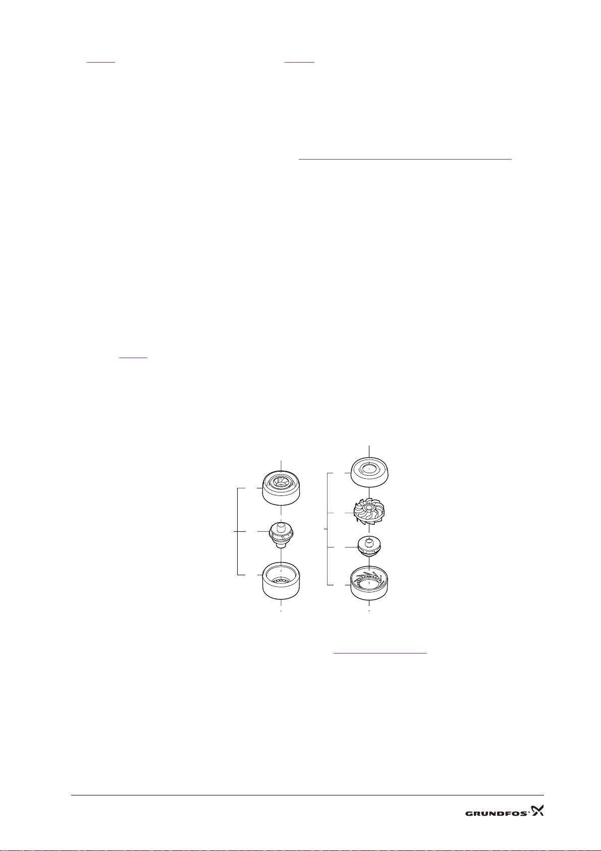
1. Assemble the chamber stack.
• Before assembling the chamber stack, assemble the chamber parts into a unit: chamber complete,
see Fig. 4..
The chamber bottom pos. 9c can be accidentally separated, and if so, assemble it before assem-
bling the chamber. The neck ring retainer should be pressed home in the chamber bottom.
In SQ 1, 2 and 3, make sure that the guide vanes pos. 32 engage with the bottom of the chamber.
• Fit the ring pos. 14a on the inlet part. Then place inlet part complete pos. 14 on a plane surface.
• Further assembly until the last chamber, see section 5. Order of assembly.
2. Fit the sleeve.
• Carefully turn the chamber stack so that the inlet part is pointing upwards.
• Turn the sleeve pos. 55 with the suction strainer upwards and carefully place it over the chamber
stack.
• Pull the sleeve with chamber stack so far out over the edge of the work top that the chamber stack
can be pushed home in the sleeve by hand.
• Turn the sleeve with chamber stack so the suction strainer is pointing downwards.
3. Fit the valve and discharge chamber.
• Place the valve casing complete on a plane surface with the bearing pos. 6 downwards.
SQ 5, 7
22, 30 SQ SQ 1, 2, 3
5, 10, 15 SQ
TM01 3137 0402
Fig. 4. Assembly of chamber
13
9b
32
9c
9c
9b
13 9a
9a