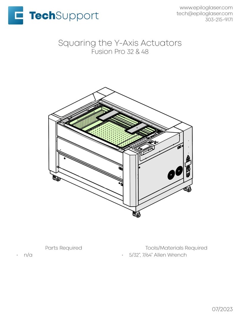
Epilog Fusion M2 User manual

• 1 •
Laser Safety Module Fusion M2 Laser Systems
Phone: 303-215-9171
Email: Tech@Epiloglaser.com
Laser Safety Module
For the Epilog Fusion M2 Laser Engraver
Revision 8/2/2017
Overview
This Document is designed to guide you
through replacing the Laser Safety Module
Assembly on an Epilog M2 with any laser source.
Requirements:
Tools:
Allen wrench - 5/32”
¼ Inch Nut Driver or Socket with
Extension.
Precision (Small) Flat Head
Screwdriver
Parts:
Laser Safety Module Assembly
HT1210
Before We Begin
In order to have the best experience possible,
collect the tools listed above and be sure that
you have all of the parts that you need before
starting this procedure. If you run into any
problems or have questions, please contact
Epilog Tech Support at 303-215-9171 or
[email protected]. For the fastest service,
please have your serial number available.
Safety
When working on or maintaining a Laser
engraver, it is likely that the sides of the machine
will be removed. Be sure that when doing
maintenance in this way, that everyone in the
room has eye protection on. Standard
Polycarbonate Safety glasses or even glass
spectacles will protect your eyes from the C02
laser.
Energized electronics can spark, shock or
force motors to suddenly move. When working
on electronics or near mechanical parts, be sure
that the machine is powered off.
Verify Correct Parts
Locate the sticker on the new module’s
packaging and take note of the part number.
1 Example Part Number
To verify that the correct part has been
received use the following table.
Laser Safety Module
Fusion M2 HT1210
If the part number is not correct, Please
contact Tech Support at 303-215-9171.

• 2 •
Laser Safety Module Fusion M2 Laser Systems
Phone: 303-215-9171
Email: Tech@Epiloglaser.com
Remove Old Part:
Remove Right
Panel
Locate the Cam
Locks on the upper
right hand panel.
Using a 5/32” Allen
wrench, turn the
lock counter
clockwise to release
the door panel.
Allow top of the
panel to swing
forward where it can
be lifted out of the
machine and
removed.
Locate the
Module
Next we will
locate the laser safety module inside of the
engraver. The top of the module can be located
on the top of the right hand side of the engraver.
You should see the module case and connections
from below, looking up.
2 Laser Safety Module from Below
Remove Mounting Nuts
Locate the Laser Safety Module on the right
side of the engraver.
From beneath locate the four mounting nuts
which fasten the module to the chassis of the
engraver. The mounting nuts can be
distinguished from the Case nuts by their
positioning, one behind each case nut.
3 Mounting Nuts
Loosen Case Nuts
If the module does not come away from the
chassis of the engraver after removing the
mounting nuts, the case nuts may also need to
be loosened to allow the module to slide freely
from the mounting studs.
4 Case Nuts
Disconnect Laser Connections
Depending on the configuration of your
engraver you may have a connection for a Fiber
Laser, a Co2 Laser, or both.
Co2 Laser
If your engraver has a C02 Laser installed,
locate and disconnect the 8-Pin Modular “RJ45”
Connecter and disconnect it. This port looks
similar to an Ethernet or Telephone jack.
Removing the Right Side
Panel

• 3 •
Laser Safety Module Fusion M2 Laser Systems
Phone: 303-215-9171
Email: Tech@Epiloglaser.com
Fiber Laser
If your engraver has a Fiber laser installed,
you will need to disconnect the DB15 connector.
This connecter has two screws which secure it to
the housing for the Laser Safety Module. Loosen
these screws and gently pull to disconnect the
cable.
5 Laser Connection Ports
Disconnect DB25 and DB15
There are two more connecters on the left
side of the Laser Safety Module which need to be
disconnected. They each have two screws
securing them to the housing of the Laser Safety
Module. Loosen the screws and gently pull to
disconnect the harness.
6 DB15 and DB9 Connections
Remove Part form Machine
You can now remove the Laser Safety Module
from the engraver.
Install New Part
Prep Case for Install
Orient the new Laser Safety Module so that
the led panel is lying flat on the table. Locate and
loosen the four case nuts.
Once the case nuts have been loosened,
squeeze the case together from either side
(where the ports are located) and continue to
apply pressure while you retighten the nuts.
Attach DB9 and DB15
Reattach the DB9 and DB15 computer cables
to the module, match the orientation of the D
shaped connecters and be sure to secure
connecter screws tightly with a precision flat
head screw driver.
Attach Laser Connection
CO2
If your engraver is equipped with a C02 laser
source, Locate the data cable and connect the 8-

• 4 •
Laser Safety Module Fusion M2 Laser Systems
Phone: 303-215-9171
Email: Tech@Epiloglaser.com
Pin Modular (RJ45) plug into the Modular Jack on
the Laser Safety Module.
Fiber
If your engraver is equipped with a Fiber
Laser source, locate the data cable and connect
it to the DB25 Port on the Laser Safety Module.
Secure Part
Place the new Laser Safety Module onto the
mounting studs so that the LED Panel can be
seen from the exterior of the engraver and
replace the Mounting Nuts.
Power on and Update
Power on the engraver and follow the
instructions on the display. Sometimes the
firmware in other parts of the engraver will need
to synchronize and update to the new part. Do
not power off the engraver until the instructed
or the display reads “Job”.
Complete
Other Epilog Engraver manuals
