Epiroc SB Series Maintenance and service guide
SB 702, 1102
Safety and operating instructions
Hydraulic breakers
© Construction Tools PC AB | 9800 1273 01 | 2020-04-03
Original Instructions


Contents
© Construction Tools PC AB | 9800 1273 01 | 2020-04-03
Original Instructions
3
Table of Contents
1 Introduction ................................................................................................................................6
1.1 About the Safety and operating instructions ...................................................................................................6
2 Safety instructions.....................................................................................................................6
2.1 Safety signal words ............................................................................................................................................6
2.2 Personal precautions and qualifications ..........................................................................................................6
2.2.1 Transport ...........................................................................................................................................................6
2.2.2 Installation, storage, maintenance and disposal................................................................................................6
2.2.3 Operation...........................................................................................................................................................6
2.2.4 Testing...............................................................................................................................................................7
2.2.5 Personal protective equipment ..........................................................................................................................7
2.2.6 Drugs, alcohol or medication .............................................................................................................................7
2.3 Carrier, precautions ............................................................................................................................................7
2.4 Installation, precautions.....................................................................................................................................7
2.4.1 Hydraulic system ...............................................................................................................................................7
2.4.2 Assembly or disassembly ..................................................................................................................................8
2.5 Operation, precautions.......................................................................................................................................8
2.6 Maintenance, precautions ..................................................................................................................................9
2.7 Storage, precautions ........................................................................................................................................10
3 Overview ...................................................................................................................................11
3.1 Design and function..........................................................................................................................................11
3.2 Main parts ..........................................................................................................................................................11
3.3 Labels.................................................................................................................................................................12
3.3.1 Data plate ........................................................................................................................................................12
3.3.2 Noise level label ..............................................................................................................................................12
3.3.3 Labels on the accumulator ..............................................................................................................................12
3.4 Guarantee .........................................................................................................................................................12
4 Transport ..................................................................................................................................13
4.1 Lifting the hydraulic breaker............................................................................................................................13
4.2 Transport using a forklift .................................................................................................................................13
4.3 Transport using a lorry.....................................................................................................................................13
5 Installation ................................................................................................................................13
5.1 Hoses and connections....................................................................................................................................13
5.2 Hydraulic oil.......................................................................................................................................................14
5.3 Assembly ...........................................................................................................................................................14
5.4 Pressure adjustment.........................................................................................................................................16
5.5 Water flushing ...................................................................................................................................................16
5.6 Working tool ......................................................................................................................................................16
5.6.1 Selecting the right working tool........................................................................................................................16
5.6.2 Changing the working tool ...............................................................................................................................17
6 Operation ..................................................................................................................................18
6.1 Preparation before breaking ............................................................................................................................18
6.1.1 Operating temperatures...................................................................................................................................18
6.1.2 Engine rpm ......................................................................................................................................................18

Contents
4 © Construction Tools PC AB | 9800 1273 01 | 2020-04-03
Original Instructions
6.2 Operating ...........................................................................................................................................................18
6.2.1 Risk area .........................................................................................................................................................18
6.2.2 Breaking ..........................................................................................................................................................18
6.2.3 Breaking under water ......................................................................................................................................20
6.2.4 Special applications.........................................................................................................................................20
7 Maintenance .............................................................................................................................20
7.1 Cleaning .............................................................................................................................................................21
7.2 Every second hour............................................................................................................................................21
7.2.1 Lubricating with a grease gun..........................................................................................................................21
7.2.2 Automatic lubrication .......................................................................................................................................21
7.3 Every day ...........................................................................................................................................................21
7.3.1 Change wear plate and bolts...........................................................................................................................21
7.4 Every week.........................................................................................................................................................21
7.4.1 Wear limits.......................................................................................................................................................22
7.4.2 Changing the lower bushing ............................................................................................................................22
7.5 Every year ..........................................................................................................................................................23
8 Storage......................................................................................................................................23
9 Disposal ....................................................................................................................................23
10 Troubleshooting.......................................................................................................................24
10.1 Hydraulic breaker does not start .....................................................................................................................24
10.2 Impact force too low .........................................................................................................................................24
10.3 Oil leaks .............................................................................................................................................................24
10.4 Hydraulic breaker operates too slow ..............................................................................................................24
10.5 Operating temperature too high ......................................................................................................................25
11 Technical data ..........................................................................................................................26
11.1 Machine data .....................................................................................................................................................26
11.2 Capacities ..........................................................................................................................................................26
11.3 Noise declaration statement ............................................................................................................................27
11.4 Flow diagrams for the correct operating pressure ........................................................................................28
11.4.1 SB 702: 120-170 bar (1740-2466 psi) .............................................................................................................28
11.4.2 SB 1102: 130-180 bar (1886-2611 psi) ...........................................................................................................29
12 EC Declaration of Conformity .................................................................................................30
12.1 EC Declaration of Conformity (EC Directive 2006/42/EC) .............................................................................30

Contents
© Construction Tools PC AB | 9800 1273 01 | 2020-04-03
Original Instructions
5

Safety and operating instructions
6 © Construction Tools PC AB | 9800 1273 01 | 2020-04-03
Original Instructions
1 Introduction
Epiroc is a leading productivity partner for the mining, in-
frastructure and natural resources industries. With cut-
ting-edge technology, Epiroc develops and produces in-
novative drill rigs, rock excavation and construction
equipment, and provides world-class service and con-
sumables.
The company was founded in Stockholm, Sweden, and
has passionate people supporting and collaborating with
customers in more than 150 countries.
Construction Tools PC AB
Box 703
391 27 Kalmar
Sweden
1.1 About the Safety and
operating instructions
The aim of the instructions is to provide you with knowl-
edge of how to use the hydraulic breaker in an efficient,
safe way. The instructions also give you advice and tell
you how to perform regular maintenance on the hy-
draulic breaker.
Before using the hydraulic breaker for the first time you
must read these instructions carefully and understand all
of them.
2 Safety instructions
To reduce the risk of serious injury or death to yourself
or others, read and understand the Safety and operating
instruction before installing, operating, repairing, main-
taining, or changing accessories on the machine.
Post this Safety and operating instruction at work loca-
tions, provide copies to employees, and make sure that
everyone reads the Safety and operating instruction be-
fore operating or servicing the machine. For professional
use only.
In addition, the operator or the operator's employer must
assess the specific risks that may be present as a result
of each use of the machine.
Save all warnings and instructions for future reference.
2.1 Safety signal words
The safety signal words Danger, Warning and Caution
have the following meanings:
DANGER Indicates a hazardous situation
which, if not avoided, will result in
death or serious injury.
WARNING Indicates a hazardous situation
which, if not avoided, could result in
death or serious injury.
CAUTION Indicates a hazardous situation
which, if not avoided, could result in
minor or moderate injury.
2.2 Personal precautions and
qualifications
Only qualified and trained persons may operate or main-
tain the machine. They must be physically able to handle
the bulk, weight, and power of the tool. Always use your
common sense and good judgement.
2.2.1 Transport
Transport of the hydraulic breaker may only be under-
taken by persons who:
• are authorised to operate a crane or fork-lift truck in
conformity with the applicable national directives,
• are aware of all the relevant national safety instruc-
tions and accident prevention instructions
• and have read and understood the safety and trans-
port chapters of this manual.
2.2.2 Installation, storage, maintenance
and disposal
Installation, storage, maintenance and disposal of the
hydraulic breaker may only be undertaken by persons
who:
• are aware of all the relevant national safety instruc-
tions and accident prevention instructions
• and have read and understood the Safety and oper-
ating instructions.
2.2.3 Operation
Operation of the hydraulic breaker may only be under-
taken by qualified carrier operators. Carrier operators
are qualified if they:
• are trained to operate a carrier in conformity with na-
tional directives,
• are aware of all the relevant national safety instruc-
tions and accident prevention instructions
• and have read and understood the Safety and oper-
ating instructions.

Safety and operating instructions
© Construction Tools PC AB | 9800 1273 01 | 2020-04-03
Original Instructions
7
2.2.4 Testing
Testing of the hydraulic installation must only be carried
out by professional technicians. The technicians must be
authorised to approve a hydraulic installation in accor-
dance with national directives.
2.2.5 Personal protective equipment
Always use approved protective equipment. Operators
and all other persons in the working area must wear pro-
tective equipment, including at a minimum:
• Protective helmet
• Hearing protection
• Impact resistant eye protection with side protection
• Respiratory protection when appropriate
• Protective gloves
• Proper protective boots
• Appropriate work overall or similar clothing (not
loose-fitting) that covers your arms and legs.
2.2.6 Drugs, alcohol or medication
WARNING Drugs, alcohol or medication
Drugs, alcohol or medication may impair your judgment
and powers of concentration. Poor reactions and incor-
rect assessments can lead to severe accidents or death.
uNever use the machine when you are tired or under
the influence of drugs, alcohol or medication.
uNo person who is under the influence of drugs, alco-
hol or medication may operate the machine.
2.3 Carrier, precautions
Before using or transporting the carrier with the hydraulic
breaker attached, carefully read the carrier manufac-
turer's safety regulations and operating instructions.
Make sure that the carrier is equipped with adequate
protective features, including a protective screen in front
of the operator.
The hydraulic breaker must only be mounted on a carrier
with sufficient load capacity.
Carriers without sufficient load capacity will not provide
the required degree of stability and could even fall over
during hydraulic breaker use, causing injury and dam-
age.
2.4 Installation, precautions
2.4.1 Hydraulic system
DANGER Compressed gas, explosion hazard
The integrated piston accumulator is pressurized even
when the hydraulic system is shut off. To dismount the
accumulator without first releasing the nitrogen gas can
cause serious personal injury or death.
uFill the integrated piston accumulator with nitrogen
(N2) only.
uOnly authorised personnel are qualified to work with
the accumulator.
WARNING Hydraulic oil at high pressure
Thin jets of hydraulic oil under high pressure can pene-
trate the skin and cause permanent injury.
uImmediately consult a doctor if hydraulic oil has pen-
etrated the skin.
uNever use your fingers to check for hydraulic fluid
leaks.
uKeep your face away from any possible leaks.
WARNING Hydraulic oil
Spilled hydraulic oil can cause burns, accidents due to
slippery conditions and will also harm the environment.
uTake care of all spilled oil and handle it according to
your safety and environmental regulations.
uNever dismount the hydraulic machine when the hy-
draulic oil is hot.
uNever run any hydraulic lines for attachment of the
hydraulic machine through the drivers cab.
CAUTION Skin eczema
Hydraulic oil can cause eczema if it comes in contact
with the skin.
uAvoid getting hydraulic oil on your hands.
uAlways use protective gloves when working with hy-
draulic oil.
uWash hands after contact with hydraulic oil.

Safety and operating instructions
8 © Construction Tools PC AB | 9800 1273 01 | 2020-04-03
Original Instructions
2.4.2 Assembly or disassembly
WARNING Moving parts
Risk for leaking oil and personal injury, such as crushed
hands and fingers.
uNever check bores or passages with hands or fin-
gers.
uAny boom movements must only be done in cooper-
ation with the personnel mounting the hydraulic
breaker.
uIf the hydraulic breaker is mounted on a quick hitch
coupling, make sure it is locked securely and all risks
of the hydraulic breaker coming loose are eliminated.
2.5 Operation, precautions
DANGER Explosion hazard
If a working tool comes into contact with explosives or
explosive gases, an explosion could occur. When work-
ing on certain materials and when using certain materi-
als in machine parts, sparks and ignition can occur. Ex-
plosions will lead to severe injuries or death.
uNever operate the machine in any explosive environ-
ment.
uNever use the machine near flammable materials,
fumes or dust.
uMake sure that there are no undetected sources of
gas or explosives.
WARNING Operating pressure
If the maximum operating pressure for the hydraulic ma-
chine is exceeded, the accumulator can be over charged
which can result in material damage and personal injury.
uAlways run the hydraulic machine with the correct
operating pressure. See "Technical data".
WARNING Dust and fume hazard
Dusts and/or fumes generated or dispersed when using
the machine may cause serious and permanent respira-
tory disease, illness, or other bodily injury (for example,
silicosis or other irreversible lung disease that can be fa-
tal, cancer, birth defects, and/or skin inflammation).
Some dusts and fumes created by drilling, breaking,
hammering, sawing, grinding and other construction ac-
tivities contain substances known to the State of Califor-
nia and other authorities to cause respiratory disease,
cancer, birth defects, or other reproductive harm. Some
examples of such substances are:
uCrystalline silica, cement, and other masonry products.
uArsenic and chromium from chemically-treated rubber.
uLead from lead-based paints.
Dust and fumes in the air can be invisible to the naked
eye, so do not rely on eye sight to determine if there is
dust or fumes in the air.
To reduce the risk of exposure to dust and fumes, do all
of the following:
uPerform site-specific risk assessment. The risk as-
sessment should include dust and fumes created by
the use of the machine and the potential for disturb-
ing existing dust.
uUse proper engineering controls to minimize the
amount of dust and fumes in the air and to minimize
build-up on equipment, surfaces, clothing, and body
parts. Examples of controls include: exhaust ventila-
tion and dust collection systems, water sprays, and
wet drilling. Control dusts and fumes at the source
where possible. Make sure that controls are properly
installed, maintained and correctly used.
uWear, maintain and correctly use respiratory protec-
tion as instructed by your employer and as required
by occupational health and safety regulations. The
respiratory protection must be effective for the type
of substance at issue (and if applicable, approved by
relevant governmental authority).
uWork in a well ventilated area.
uIf the machine has an exhaust, direct the exhaust so
as to reduce disturbance of dust in a dust filled envi-
ronment.
uOperate and maintain the machine as recommended
in the operating and safety instructions
uSelect, maintain and replace consumables/ working
tools/ other accessories as recommended in the op-
erating and safety instructions. Incorrect selection or
lack of maintenance of consumables/ inserted tools/
other accessories may cause an unnecessary in-
crease in dust or fumes.
uWear washable or disposable protective clothes at
the worksite, and shower and change into clean
clothes before leaving the worksite to reduce expo-
sure of dust and fumes to yourself, other persons,
cars, homes, and other areas.
uAvoid eating, drinking, and using tobacco products in
areas where there is dust or fumes.
uWash your hands and face thoroughly as soon as
possible upon leaving the exposure area, and always
before eating, drinking, using tobacco products, or
making contact with other persons.
uComply with all applicable laws and regulations, in-
cluding occupational health and safety regulations.
uParticipate in air monitoring, medical examination
programs, and health and safety training programs
provided by your employer or trade organizations
and in accordance with occupational health and

Safety and operating instructions
© Construction Tools PC AB | 9800 1273 01 | 2020-04-03
Original Instructions
9
safety regulations and recommendations. Consult
with physicians experienced with relevant occupa-
tional medicine.
uWork with your employer and trade organization to
reduce dust and fume exposure at the worksite and
to reduce the risks. Effective health and safety pro-
grams, policies and procedures for protecting work-
ers and others against harmful exposure to dust and
fumes should be established and implemented
based on advice from health and safety experts.
Consult with experts.
uResidues of hazardous substances on the machine
can be a risk. Before undertaking any maintenance
on the machine, clean it thoroughly.
WARNING Electric shock
The hydraulic breaker is not insulated against electric
current. If the hydraulic breaker come in contact with
electric circuits or other electrical power sources, there is
a risk of severe injury or death.
uNever work in the proximity of electric circuits or
other electrical power sources.
uMake sure there are no hidden electric circuits in
your working area.
WARNING Projectiles
Failure of the work piece, of accessories, or even of the
hydraulic breaker itself may generate high velocity pro-
jectiles. During breaking, splinters, or other particles may
become projectiles and cause bodily injury by striking
the operator or other persons. Also, breakage of the
work piece, accessories, or the working tool may gener-
ate high velocity projectiles that can cause bodily injury.
In addition, objects falling from a height can cause bodily
injury. To reduce risks:
uClose off the working area.
uBefore starting, make sure that no persons are in the
danger area, 20 meters both horizontally and verti-
cally from the hydraulic breaker.
uImmediately switch off the hydraulic breaker when
persons are present in the danger area.
uPress the working tool against the working surface
before you start.
uNever operate unless the working tool is retained in
the hydraulic breaker with a proper tool retainer.
WARNING Noise hazard
High noise levels can cause permanent and disabling
hearing loss and other problems such as tinnitus (ring-
ing, buzzing, whistling, or humming in the ears). To re-
duce risks and prevent an unnecessary increase in noise
levels:
uRisk assessment of these hazards and implementa-
tion of appropriate controls is essential.
uOperate and maintain the machine as recommended
in these instructions.
uSelect, maintain and replace the working tool as rec-
ommended in these instructions.
uIf the machine has a silencer, check that it is in place
and in good working condition.
uAlways use hearing protection.
uUse damping material to prevent work pieces from
'ringing'.
2.6 Maintenance, precautions
WARNING Involuntary start
An involuntary start of the hydraulic breaker can lead to
severe injuries.
uFollow the instructions in the carrier manual to pre-
vent involuntary start of the hydraulic breaker.
uInstallation of a start circuit on the hydraulic breaker
must be made in a way that avoids any unintentional
starts.
uA foot pedal on the carrier must be equipped with a
protection cover.
WARNING Hydraulic system under high pressure
Maintenance work on a hydraulic breaker under pres-
sure can lead to severe injuries. Connections can loosen
suddenly, parts can suddenly move and hydraulic oil can
be ejected.
uDepressurise the hydraulic system before performing
maintenance on the hydraulic breaker or the carrier.
WARNING Machine modification
Any machine modification may result in bodily injuries to
yourself or others.
uNever modify the machine. Modified machines are
not covered by warranty or product liability.
uAlways use approved original parts, tools, and ac-
cessories.
uChange damaged parts immediately.
uReplace worn components in good time.

Safety and operating instructions
10 © Construction Tools PC AB | 9800 1273 01 | 2020-04-03
Original Instructions
WARNING Hot working tool
The tip of the working tool gets very hot during opera-
tion. Touching it may lead to burns.
uNever touch the hot working tool.
uIf you have to carry out any activities, wait for the
working tool to cool down first.
WARNING Working tool hazards
Accidental engagement of the start and stop device dur-
ing maintenance or installation can cause serious in-
juries, when the power source is connected.
uNever inspect, clean, install, or remove the working
tool while the power source is connected.
2.7 Storage, precautions
WARNING Heavy hydraulic breaker and working
tool
The hydraulic breaker and the working tool are heavy
equipment. If the breaker or working tool topple over or
fall down from where they are stored, it can result in ma-
terial damage and personal injury.
uStore the hydraulic breaker and the working tool so
that falling or rolling down is prevented.

Safety and operating instructions
© Construction Tools PC AB | 9800 1273 01 | 2020-04-03
Original Instructions
11
3 Overview
To reduce the risk of serious injury or death to your-
self or others, read the Safety instructions section
found on the previous pages of this manual before
operating the machine.
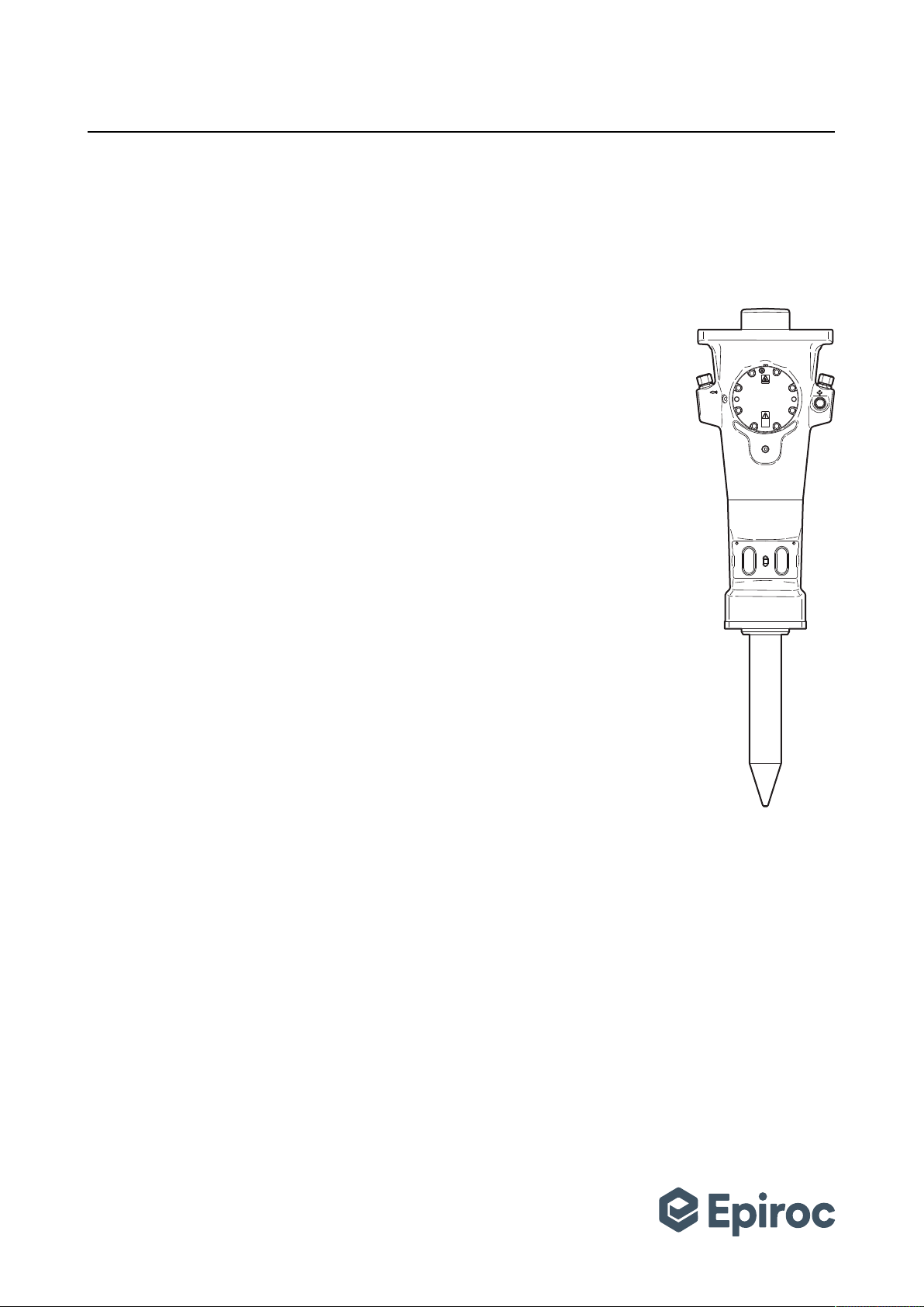
3.1 Design and function
SB is a range of rig mounted hydraulic breakers de-
signed for all kinds of demolition works. No other use is
permitted.
SB has a solid body which means that the breaker body
is made in one piece. The accumulator is integrated with
the body.
The hydraulic breaker is operated from the driver's cab
of the carrier using the carrier's hydraulic system. The
breaker frequency is controlled by the oil flow from the
carrier.
Recommended working tools are listed in the spare
parts list.
3.2 Main parts
A
C
B
E
F
D
G
H
I
SB 702
SB 1102
A. Restrictor
B. Hammer body
C. Lock pin
D. Pressure relief valve
E. Accumulator
F. Oil drainage plug
G. Lock buffer
H. Tool retainer
I. Bushing
Safety and operating instructions
12 © Construction Tools PC AB | 9800 1273 01 | 2020-04-03
Original Instructions
3.3 Labels
The machine is fitted with labels containing important in-
formation about personal safety and machine mainte-
nance. The labels must be in such condition that they
are easy to read. New labels can be ordered from the
spare parts list.
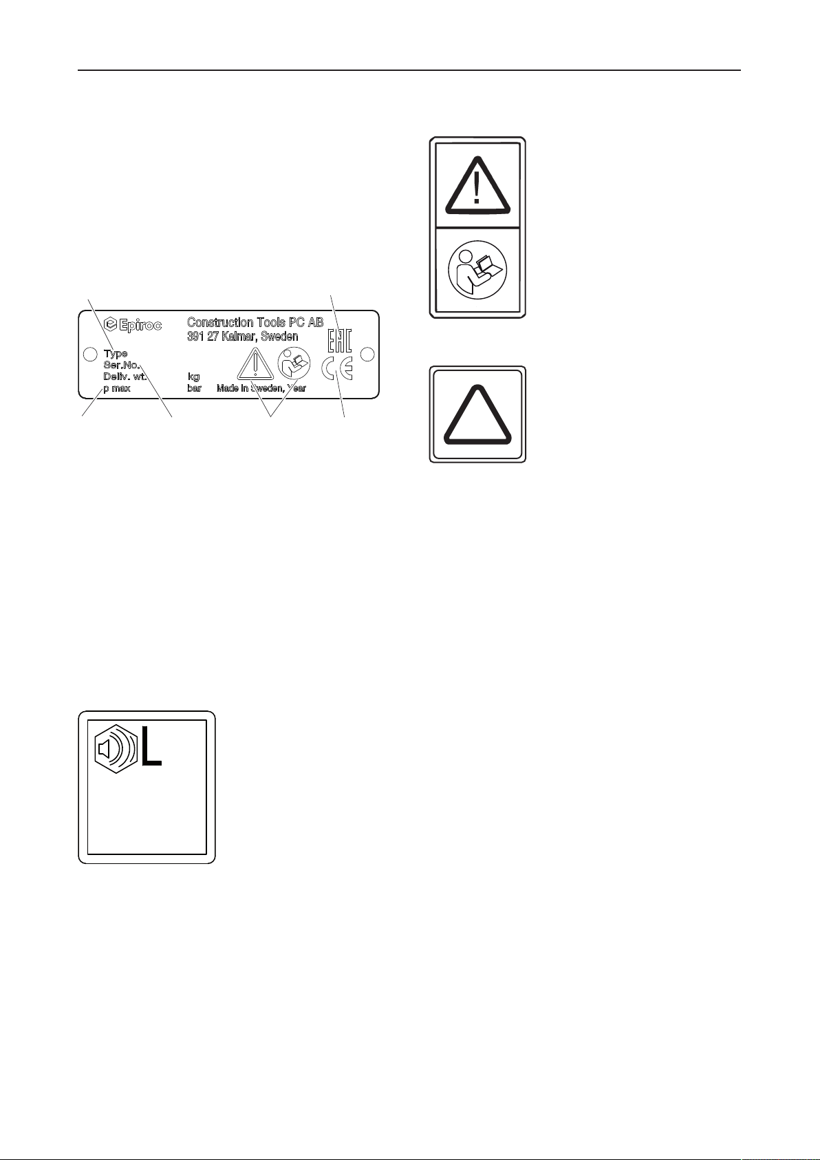
3.3.1 Data plate
A
BCDE
F
A. Machine type
B. Maximum hydraulic pressure
C. Serial number
D. The warning symbol together with the book symbol
means that the user must read the safety and oper-
ating instructions before the machine is used for the
first time.
E. The CE symbol means that the machine is EC-ap-
proved. See the EC Declaration of Conformity which
is delivered with the machine for more information.
F. The EAC symbol means that the machine is EAC
approved.
3.3.2 Noise level label
WA
xxx
dB
The label indicates the guaranteed noise level corre-
sponding to EC-directive 2000/14/EC. See "Technical
data" for accurate noise level.
3.3.3 Labels on the accumulator
Read through the overhaul instructions carefully before
servicing or charging.
2
N
The accumulator must only be charged with Nitrogen.
NOTICE Only certified personnel are allowed to work
with the accumulator.
3.4 Guarantee
The guarantee or product liability will be invalidated by
the following:
• Use other than intended
• Maintenance work not being carried out or being
carried out incorrectly
• The use of the wrong consumables
• The use of non-approved parts
• Damage due to wear
• Special applications without the required safety facil-
ities
• Damage due to improper storage
• Changes not carried out by or in consultation with
the manufacturer

Safety and operating instructions
© Construction Tools PC AB | 9800 1273 01 | 2020-04-03
Original Instructions
13
4 Transport
WARNING Falling hydraulic breaker
If the hydraulic breaker is tipping over and falling, it may
cause serious injury.
uPlace the hydraulic breaker in a safe position where
it cannot fall over and cause damage.
NOTICE Air freight restrictions
HATCON contains an activated SIM card (radio transmit-
ting device) and an encased lithium ion battery after acti-
vation step has been finalized. Both parts are regulated
for air transport.
uConsult your forwarder or local customer center/
dealer about any restrictions for air freight.
4.1 Lifting the hydraulic breaker
Carefully check that the carrier is stable enough when
transporting, performing maintenance, or other kinds of
work with the hydraulic breaker.
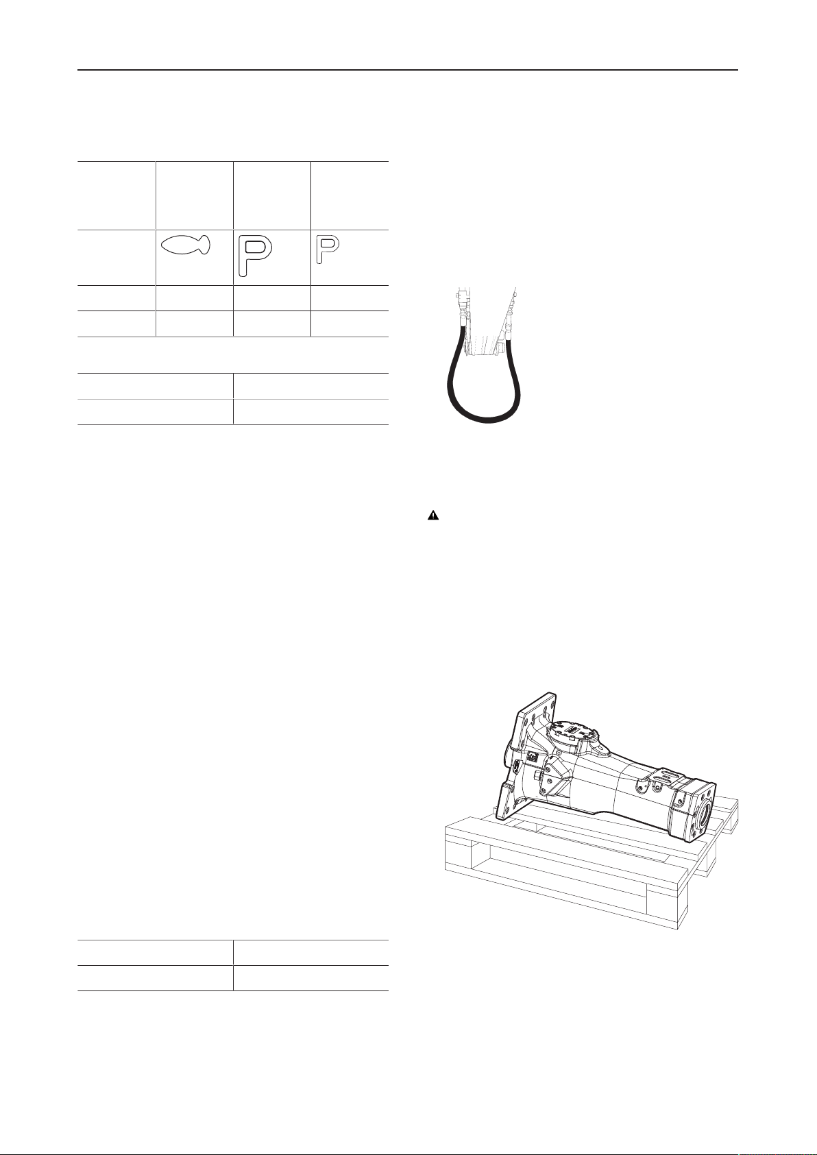
The hydraulic breaker is delivered in a box. To lift the hy-
draulic breaker in a safe way, fit the lifting strap in the
manner shown in the illustration below.
4.2 Transport using a forklift
When using a forklift. Place the hydraulic breaker at a
pallet. Use wedges and strapping to secure it. Slowly lift
and transport the hydraulic breaker to its intended desti-
nation.
4.3 Transport using a lorry
Put the hydraulic breaker on an anti-slip mat at the lorry.
Secure the machine to the loading surface with straps.
Observe all the applicable national and regional regula-
tions on securing loads.
5 Installation
Before installing the hydraulic breaker on the carrier or
operating it, read the operation manual and safety in-
structions provided by the carrier manufacturer. Follow
all instructions.
The carrier must have the appropriate hydraulic system
for operation of the breaker.
If the carrier is too large for the hydraulic breaker it may
lead to broken working tools and increased wear. See
"Technical data" for choosing suitable carrier.
The safety equipment in the hydraulic system must be
checked for quality (CE mark, etc.), suitability and func-
tionability by a professional or authorised supervisor be-
fore use.
5.1 Hoses and connections
WARNING Whipping hydraulic hose
Hydraulic hoses under pressure can whip uncontrollably
if screws loosen or are loosened. A whipping hydraulic
hose can cause severe injuries.
uDepressurize the hydraulic system before loosening
the connection of a hydraulic hose.
uTighten the nuts on the connections of the hydraulic
hoses to the required torque.
Type of nipple: ORFS standard nipple. The nipple di-
mensions can be found in the Spare parts list.
The quality of the hydraulic hoses must be 2SC (accord-
ing to EN857) or better when connecting the breaker to
the carrier. If quick couplings are to be used, we recom-
mend using the 'Flat Face' quick coupling. This type is
sturdy and easy to clean. The quick coupling pressure
class must agree with the carrier's working pressure.
Always clean the quick couplings before mounting or dis-
mounting. Always plug hoses and hose nipples with tight
and clean end caps when dismounting.
Hose connections
Right (As seen from operator’s seat)
Air flushing Central lu-
brication
Tank, re-
turn line
Symbol
SB 702 G ½ in. G ¼ in. G 1 in.
SB 1102 G ½ in. G ¼ in. G 1 in.
Safety and operating instructions
14 © Construction Tools PC AB | 9800 1273 01 | 2020-04-03
Original Instructions
Hose connections
Left (As seen from operator's seat)
Water Pressure to
breaker
Pressure
for Con-
tiLube II mi-
cro
Symbol
SB 702 G ¼ in. G 1 in. G ¼ in.
SB 1102 G ¼ in. G 1 in. G ¼ in.
Tightening torque for pressure and return hoses
SB 702 300 Nm (221 ft lbs)
SB 1102 315 Nm (232 ft lbs)
NOTICE The tightening torques in the table above are
valid when the pressure and return hose are mounted di-
rectly on the hydraulic breaker's connection nipple. If the
pressure and return hose are connected with an addi-
tional connection nipple, another tightening torques must
be used.
5.2 Hydraulic oil
Normally the type of hydraulic oil the carrier is using also
works for the hydraulic breaker. When a hydraulic
breaker is connected to the carrier, the hydraulic oil will
get dirty faster. Check and follow the carrier's instruc-
tions for changing oil and oil filter. It is common to
change the oil filter more frequent when a hydraulic
breaker is installed.
SB hydraulic breakers are equipped with an oil drainage
plug to drain all oil before dismounting. This is to reduce
the risk of spilling oil.
NOTICE When the SB breaker is delivered it contains
some mineral based hydraulic oil. Before connecting to
the carrier's hydraulic system, check which type of hy-
draulic oil the carrier is using. Mixing different types of
hydraulic oil may destroy the lubrication quality which
can lead to machine damage.
In order to protect the environment we recommend the
use of biologically degradable hydraulic oil.
Viscosity
Viscosity (permitted) 15-100 cSt
NOTICE Always use clean oil and filling equipment.
5.3 Assembly
Circulate the hydraulic oil before connecting the ma-
chine. This is to make sure that the hydraulic oil is clean.
Use the same routine when changing a hydraulic oil
hose.
1. Connect the pressure and return hose.
2. Run the hydraulic oil through the carrier's oil filter for
approximately 3minutes to make sure that the hoses
are clean.
WARNING Falling breaker can cause injuries
uPlace the breaker in a safe position where it can not
fall over and cause damage.
Preparation
1. Place the breaker in a position where it is easy and
safe to mount the adapter plate.
NOTICE Mount the breaker so that the accumulator
faces the operator's cabin, to reduce the risk of accu-
mulator damage.
Mounting the adapter plate
1. Place the adapter plate on the hydraulic breaker.
Safety and operating instructions
© Construction Tools PC AB | 9800 1273 01 | 2020-04-03
Original Instructions
15
2. Place NYLOK BLUE PATCH™ (Known as TUF-LOK®
in Europe) screws through all bore holes and fit nuts
to the screws.
If NYLOK BLUE PATCH™ (Known as TUF-LOK® in
Europe) screws are not available we recommend us-
ing NORD-LOCK® washers under bolts and nuts.
(NYLOK BLUE PATCH is a trademark of Nylok Cor-
poration. TUF-LOK is a registered trademark of Nylok
Corporation in Europe. NORD-LOCK is a registered
trademark of Nord-Lock International AB.)
3. Tighten the nuts, see the tightening torque in the ta-
ble below.
Adapter plate Tightening torque
SB 702 400 Nm (295 ft lbs)
SB 1102 1385 Nm (1022 ft lbs)
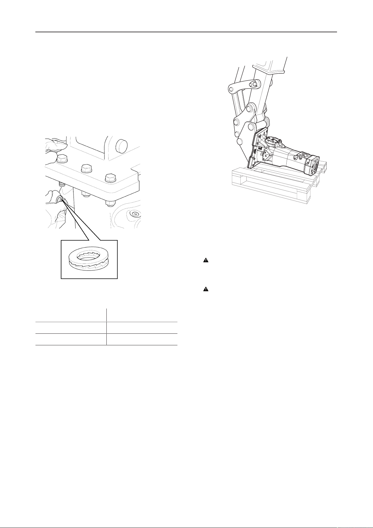
Connecting the breaker to the carrier
1. Position the breaker in a safe way during installation.
The pressure inlet on the hydraulic breaker is on the
left side when you are facing the accumulator. If the
pressure hose is on the other side of the boom you
can cross the hoses or turn the hydraulic breaker.
2. Carefully lower the stick of the boom into the adapter.
WARNING Moving parts can crush and cut
uNever check bores or passages with hands or fin-
gers.
WARNING Injury by impacts
A sudden movement of the carrier may cause your
assistant to be hit and injured by the boom or the hy-
draulic breaker.
uOnly move the boom very slowly and in a con-
trolled manner while an assistant is within the risk
area.
uAlways keep sight of your assistant.
uAgree with the assistant on clear hand signals for
use during the mounting procedure.
An assistant must direct the movement of the boom
until the bores in the boom are flush with those in the
adapter.
3. Insert the pin and lock.
4. Lift up the hydraulic breaker using the boom.
5. Extend the bucket cylinder until the bore in the toggle
is flush with those in the adapter. Insert toggle pin
and lock.
Safety and operating instructions
16 © Construction Tools PC AB | 9800 1273 01 | 2020-04-03
Original Instructions
6. After mounting the breaker, carefully extend and re-
tract the bucket cylinder to its full extent in each di-
rection. It is important that the cylinder can be fully
extended and retracted without any difficulty.
5.4 Pressure adjustment
A B
Max operating pres-
sure, bar (psi)
Normal operating
pressure, bar (psi)
SB 702 170 (2466) 150 - 170
(2176 - 2466)
SB 1102 180 (2611) 160 - 180
(2321 - 2611)
The hydraulic breaker is equipped with a pressure relief
valve which secures the breaker. The operating pressure
of the machine is checked with a pressure gauge and
adjusted while operating the hydraulic breaker.
nIf the operating pressure is more than(A) the pres-
sure must be decreased. Reduce the oil flow from the
carrier until the pressure is down to(A). This adjust-
ment is important to ensure that the built in pressure
relief valve in the breaker does not open and leak oil
back to the tank and create heating problems.
nIf the operating pressure is between(B), normally no
adjustment is needed.
nIf the carrier's oil flow is too low to retain an accept-
able operating pressure the restrictor in the breaker
needs to be changed. See flow diagrams in "Techni-
cal data" to choose the best restrictor for your appli-
cation.
Position the hydraulic breaker vertically towards solid
bedrock or similar to adjust the pressure using a pres-
sure gauge.
5.5 Water flushing
The hydraulic breaker is prepared for water flushing, this
function is to bind the dust when performing demolition
operations.
When connecting water flushing the plug in the front of
the breaker must be exchanged with a water nozzle. See
the Spare parts list for ordering a new water nozzle.
Use a ¼ in. hydraulic hose with a JIC connection as a
proper water hose. Contact your nearest authorised
workshop for further instructions.
NOTICE It is recommended to use water flushing to re-
duce the wear on the hydraulic breaker during tunnel
and dust-intensive applications.
5.6 Working tool
5.6.1 Selecting the right working tool
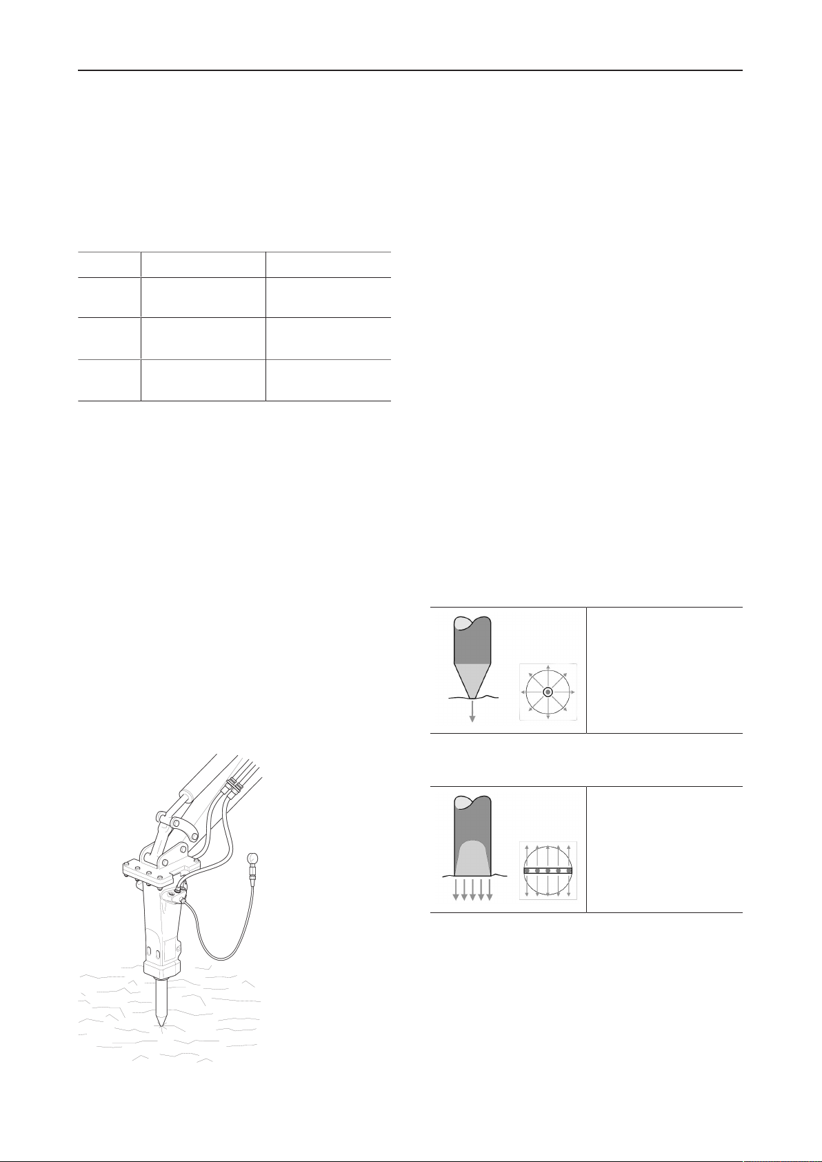
5.6.1.1 Conical moil point
• Very good penetra-
tion
• Regular spread of
wedge action
• No torsion effect
5.6.1.2 Chisels and spades
• Very good spread of
wedge action
• Good penetration
• Torsion effect

Safety and operating instructions
© Construction Tools PC AB | 9800 1273 01 | 2020-04-03
Original Instructions
17
5.6.1.3 Blunt tool
• Very good energy ap-
plication
• Optimum breaking ef-
fect
• No torsion effect
5.6.2 Changing the working tool
WARNING Running engine
Changing the inserted tool or accessories while the car-
rier's engine is running can cause serious injury.
uSecure the carrier against involuntary activation.
WARNING Working tool can be heavy
If the working tool is falling down, it can result in material
damage and personal injury.
uAlways lift the working tool in a safe way.
1. Shut the carrier's engine off.
2. Dismount the working tool, use a lifting strap to re-
duce the risk of personal injury.
3. Remove and check the lock buffer. Change worn or
damaged parts.
NOTICE The lock buffer in the tool retainer lock is
made of plastic and can melt when operating in a hot
environment. If this occurs, change the standard lock
pin. Find optional spring pin in the spare parts list.
4. Clean and lubricate the bushing plentifully.
NOTICE When mounting a new working tool, it is es-
pecially important to lubricate plentifully.
5. Mount the working tool, use a lifting strap to reduce
the risk of personal injury
6. Rotate the working tool to spread the grease.
7. Mount the tool retainers, one at the time.
8. Drive in the lock pin until the lock buffer attaches in
the lock pin groove.

Safety and operating instructions
18 © Construction Tools PC AB | 9800 1273 01 | 2020-04-03
Original Instructions
6 Operation
NOTICE The hydraulic breaker or the working tool is not
to be used as a lifting device. When lifting heavy compo-
nents use the hook on the carrier arm.
6.1 Preparation before breaking
6.1.1 Operating temperatures
The operating temperatures of the hydraulic breaker are
between -20ºC (-4ºF) and +80ºC (+176ºF).
CAUTION Temperature hazard
The hydraulic breaker and the hydraulic oil system of the
carrier can be damaged if the hydraulic breaker is used
at higher or lower temperatures.
uOnly start the hydraulic breaker when the hydraulic
oil has reached the proper operating temperature.
uIf the ambient temperature is below –20ºC (-4ºF),
you must warm up the working tool and the hydraulic
breaker before use.
uIf the oil temperature exceeds +80ºC (+176ºF), you
must not use the hydraulic breaker as the oil quality
becomes inadequate which severely shortens the life
time of seals and O-rings.
6.1.2 Engine rpm
Too high engine rpm only results in increased fuel con-
sumption and increased oil temperature. Adapt the en-
gine rpm to the recommended value to give the correct
operating oil flow.
6.2 Operating
6.2.1 Risk area
Before starting the hydraulic breaker, make sure that no
persons are in the risk area, 20meters (66ft) both hori-
zontally and vertically from the hydraulic breaker.
20 m
6.2.2 Breaking
CAUTION Machine and tool hazard
Continuous operation at full extension and/or retraction
can result in damage to the hydraulic cylinders.
uAlways avoid operating the breaker with the cylinders
fully extended or retracted.
uReposition the carrier and/or boom to avoid fully ex-
tended or retracted cylinders.
uPay attention and look at what you are doing.
Never start the hydraulic breaker until both carrier and
the hydraulic breaker are in the correct position.
nDirect the hydraulic breaker in a position 90° towards
the object.

Safety and operating instructions
© Construction Tools PC AB | 9800 1273 01 | 2020-04-03
Original Instructions
19
nStart near the edge and work your way in towards the
middle. Never start in the middle of large objects.
nNever run the hydraulic breaker longer than 15sec-
onds on the same spot. Move the working tool to a
new position if the object does not break.
nNever bend with the working tool.
nUse the correct feed pressure. When the feed pres-
sure is correct the hydraulic breaker is working at its
best and the vibrations are at a minimum. Also the
wear on the bushing and inserted tool is kept to a
minimum.
nListen to the sound from the hydraulic breaker. The
sound changes if there is any bending between the
working tool and bushing.
nNever run the breaker with the boom cylinders at
their end positions. It may cause damage to the car-
rier.
nAvoid idling strokes; it causes wear on both working
tool and tool retainers.
nThe hydraulic breaker or the working tool is not to be
used as a lifting device. When lifting heavy compo-
nents use the hook on the carrier arm.

Safety and operating instructions
20 © Construction Tools PC AB | 9800 1273 01 | 2020-04-03
Original Instructions
nNever use the hydraulic breaker as a sledge hammer
to demolish material.
nNever use the hydraulic breaker to move debris.
6.2.3 Breaking under water
Hydraulic breakers can be used for operating under wa-
ter.
bar
1.5-2
NOTICE When operating under water the hydraulic
breaker must be fed with compressed air to keep the
area between the piston and the inserted tool free from
water. If the area between the piston and the inserted
tool gets filled with water, it may penetrate into the hy-
draulic oil system when the hydraulic breaker is started.
The air pressure must be 1.5-2bar (22-29psi) at the air
inlet on the breaker and the air consumption can be
found in "Technical data". Suitable air hose is a ¼ in. hy-
draulic hose with JIC connection. Contact your nearest
authorised workshop for further instructions.
6.2.4 Special applications
NOTICE Always consult the Customer Center /Dealer in
your area in case of special applications- tunnelling, high
thermal load and underwater application.
You can contact your nearest authorised workshop for
further instructions.
7 Maintenance
It is essential that regular maintenance is performed to
maintain the breakers maximum efficiency.
Equipment that is insufficiently maintained can be dan-
gerous for both the operator and persons near the
breaker. Make sure that regular maintenance routines
with lubrication are followed to keep the equipment safe
and efficient.
This manual suits for next models
2
Table of contents
Other Epiroc Power Tools manuals


Popular Power Tools manuals by other brands

AXXIOM
AXXIOM SCHMIDT BAABS manual

Balcrank
Balcrank Roughneck II 4110-022 Operation, installation, maintenance and repair guide

Yokota
Yokota YZ-TH600 instruction manual

Makita
Makita 6918D instruction manual

BIRD
BIRD Termaline 8890 Series Operation manual

PEUGEOT
PEUGEOT EnergyBrush-18VBL Assembly and using manual


