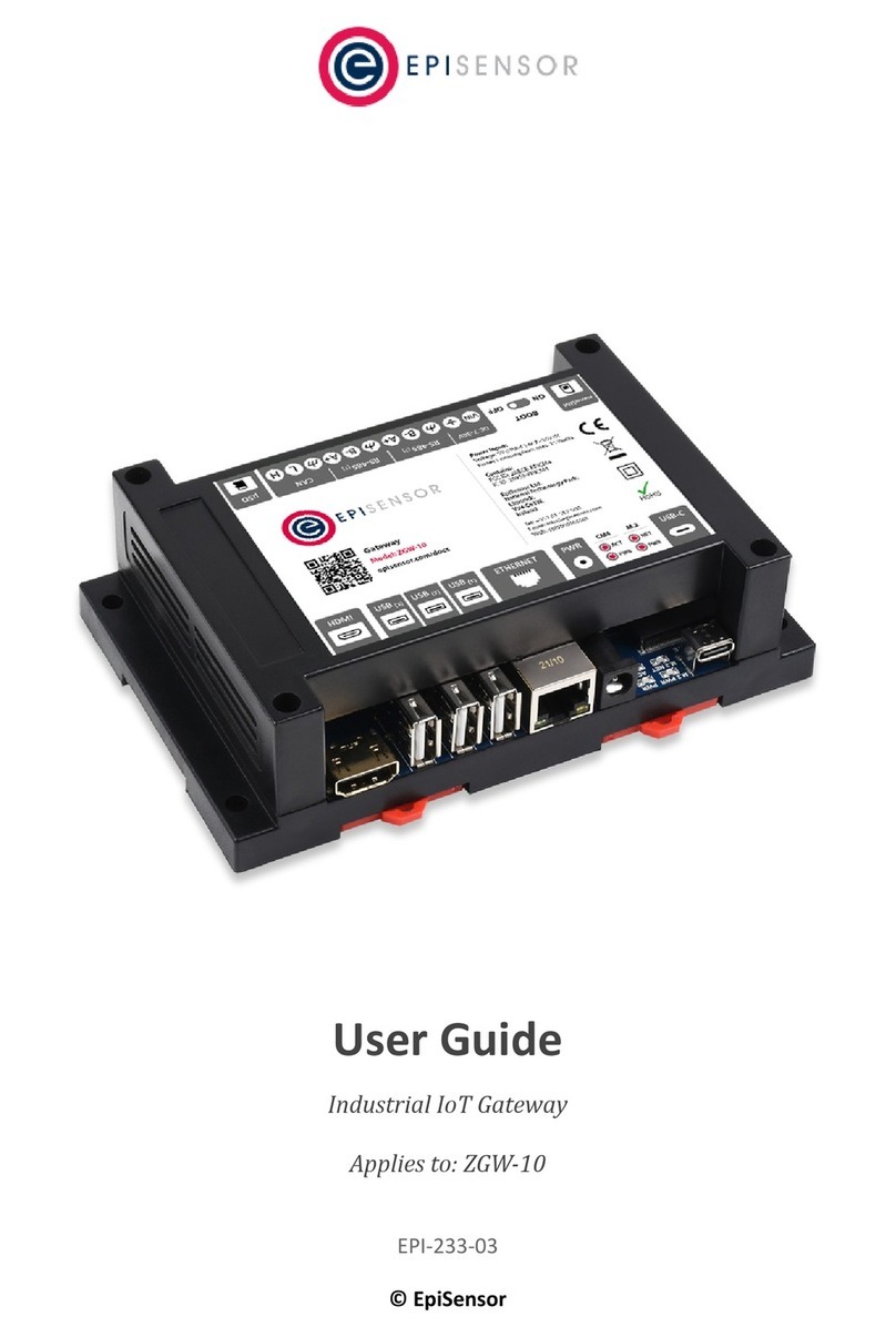
EpiSensor ZGW-10 User manual

Install Sheet
ZGW-10 // IoT Gateway
Document Ref. EPI-215-01
Installation & Safety Notes
➔EpiSensor equipment should be installed, operated, serviced and maintained only by
qualified personnel. EpiSensor does not assume any responsibility for any
consequences arising out of the use of this equipment.
➔The ZGW-10 Gateway is not designed for use in wet or dusty environments. If it is to be
installed in a wet or dusty location, it must be installed in a panel box or enclosure with
an Ingress Protection (IP) rating of IP54, IP65, or higher.
➔To reduce the risk of electric shock, power to the DC+ and DC- terminals must be
provided by a power supply or transformer/rectifier circuit that is designed with
double-insulation. The power supply or power circuit source must comply with local
codes and regulations; for example, in the USA, NEC Class 2 (SELV/limited energy
circuit, or LPS circuitry). If powered by a battery, double-insulation is not required.
➔When installing the Gateway, the responsible party or integrator shall use a supply
voltage of 7-36 VDC with a minimum rated power output of 24 Watts.
➔Ensure that the power source providing power to the Gateway is reliably grounded and
filtered such that the peak-to-peak ripple component is less than 10 percent of the input
DC voltage.
➔When installing the Gateway, use a cable appropriate for the load currents: 3-core
cable rated 5 A at 90°C (194°F) minimum, which conform to either IEC 60227 or IEC
60245. The system accepts cables from 0.8 mm to 2 mm. The maximum operating
temperature of the Gateway is 70⁰C (158°F). Do not exceed this maximum temperature
while operating the Gateway inside an enclosure. Internal heating of the Gateway
electronics, other electronics, and the lack of ventilation inside an enclosure can cause
the operating temperature of the Gateway to be greater than the outside ambient
temperature. Continuous operation of the Gateway at temperatures greater than 70⁰C
(158°F) may result in an increased failure rate and a reduction of the product life.
Ensure that the maximum operating temperature of the Gateway when placed inside an
enclosure is 70⁰C (158°F) or less.
➔Always ensure that the available power source matches the required input power of the
Gateway. Check the input power markings next to power connector(s) before making
connections. The 7-36 V DC must be compliant with local Electrical Codes and
Regulations.
➔To ensure the protection provided by the Gateway is not impaired, do not use or install
the system in any manner other than what is specified in the install sheet or user guide.
➔The system is for installation in a suitable industrial enclosure (provides electrical,
mechanical, and fire hazard protection).
➔This product is designed for specific applications and needs to be installed by qualified
personnel with RF and regulatory-related knowledge. The general user shall not
attempt to install or change the setting.
➔The product shall be installed at a location where the radiating antenna is kept 20 cm
from nearby persons in its normal operation condition in order to meet regulatory RF
exposure requirements.
➔Use only approved antenna(s). Non-approved antenna(s) may produce spurious or
excessive RF transmitting power which may lead to a violation of FCC/IC limits.
ZigBee, Ethernet and Power Connection Diagram for ZGW-10
DC Power
Supply
Left Side
Laptop
1
For instructions on configuring your
Laptop, see the ‘Quick Start’ section of the
EpiSensor Gateway User Guide
(EPI-075-02)
IMPORTANT
2Connect an Ethernet cable
between the Gateway and a
laptop
172.31.255.X
nano SIM
DC 7 - 36V
172.31.255.1
Connect only one
power source at a
time:
Either the DC terminals on
the top side, the DC barrel
jack on the bottom side
(using the provided mains
power supply), or USB-C.
3Connect a power
supply
USB-C
Connect the
ZigBee dongle
to USB port 3
as shown here

Install Sheet
ZGW-10 // IoT Gateway
Document Ref. EPI-215-01
Installation & Safety Notes
➔EpiSensor equipment should be installed, operated, serviced and maintained only by
qualified personnel. EpiSensor does not assume any responsibility for any
consequences arising out of the use of this equipment.
➔The ZGW-10 Gateway is not designed for use in wet or dusty environments. If it is to be
installed in a wet or dusty location, it must be installed in a panel box or enclosure with
an Ingress Protection (IP) rating of IP54, IP65, or higher.
➔To reduce the risk of electric shock, power to the DC+ and DC- terminals must be
provided by a power supply or transformer/rectifier circuit that is designed with
double-insulation. The power supply or power circuit source must comply with local
codes and regulations; for example, in the USA, NEC Class 2 (SELV/limited energy
circuit, or LPS circuitry). If powered by a battery, double-insulation is not required.
➔When installing the Gateway, the responsible party or integrator shall use a supply
voltage of 7-36 VDC with a minimum rated power output of 24 Watts.
➔Ensure that the power source providing power to the Gateway is reliably grounded and
filtered such that the peak-to-peak ripple component is less than 10 percent of the input
DC voltage.
➔When installing the Gateway, use a cable appropriate for the load currents: 3-core
cable rated 5 A at 90°C (194°F) minimum, which conform to either IEC 60227 or IEC
60245. The system accepts cables from 0.8 mm to 2 mm. The maximum operating
temperature of the Gateway is 70⁰C (158°F). Do not exceed this maximum temperature
while operating the Gateway inside an enclosure. Internal heating of the Gateway
electronics, other electronics, and the lack of ventilation inside an enclosure can cause
the operating temperature of the Gateway to be greater than the outside ambient
temperature. Continuous operation of the Gateway at temperatures greater than 70⁰C
(158°F) may result in an increased failure rate and a reduction of the product life.
Ensure that the maximum operating temperature of the Gateway when placed inside an
enclosure is 70⁰C (158°F) or less.
➔Always ensure that the available power source matches the required input power of the
Gateway. Check the input power markings next to power connector(s) before making
connections. The 7-36 V DC must be compliant with local Electrical Codes and
Regulations.
➔To ensure the protection provided by the Gateway is not impaired, do not use or install
the system in any manner other than what is specified in the install sheet or user guide.
➔The system is for installation in a suitable industrial enclosure (provides electrical,
mechanical, and fire hazard protection).
➔This product is designed for specific applications and needs to be installed by qualified
personnel with RF and regulatory-related knowledge. The general user shall not
attempt to install or change the setting.
➔The product shall be installed at a location where the radiating antenna is kept 20 cm
from nearby persons in its normal operation condition in order to meet regulatory RF
exposure requirements.
➔Use only approved antenna(s). Non-approved antenna(s) may produce spurious or
excessive RF transmitting power which may lead to a violation of FCC/IC limits.
Antenna Connection Diagram for ZGW-10
Left Side
1
4Wi-Fi / Bluetooth
Antenna
Secondary
cellular
antenna
2Primary
cellular
antenna
3GPS Antenna
Other manuals for ZGW-10
1
Other EpiSensor Gateway manuals
Popular Gateway manuals by other brands
ATCOM
ATCOM NanoStation 2 Configuration guide
Wisi
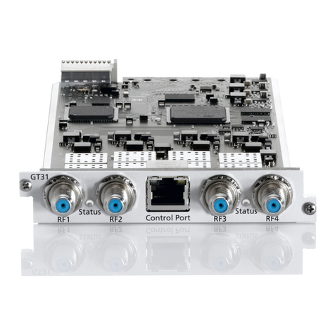
Wisi Tangram GT31 operating instructions
AT&T
AT&T RIM BlackBerry 8300 Hardware quick start guide

Avaya
Avaya CMC1 installation guide
Pulse Secure
Pulse Secure PSA300 Hardware guide
Beijer Electronics
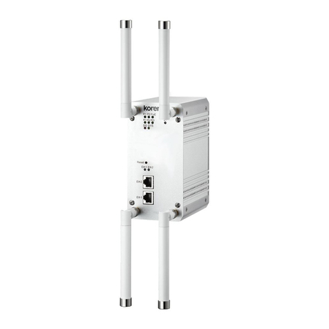
Beijer Electronics korenix JetWave 3220v3 Series user manual
