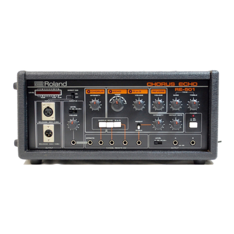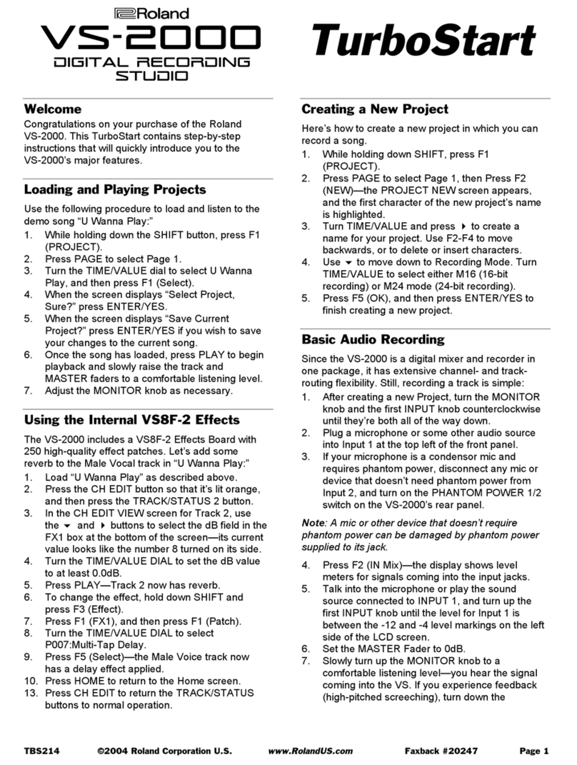
OPERATION 1. Afler making the connections, set
the INPUT MODE switch ®(rear panel)
as needed. Set both the BYPASS
switch Oand the DIMENSION MODE
@at OFF.
2. Turn on the POWER switch ©and
check that the pilot light above goes
on.
3. Adjust the level of the external
sound source so that the OUTPUT
LEVEL INDICATOR ©reads close to
•Using levels which drive the LEVEL
INDICATOR ©above "0" can cause
distortion. Using levels which cause the
LEVEL INDICATOR ©to read below
"0" will increase the noise level mthe
output signal.
4. Select
MODE© the desired DIMENSION
NAMES AND FUNCTION OF CONTROLS
FRONT PANEL
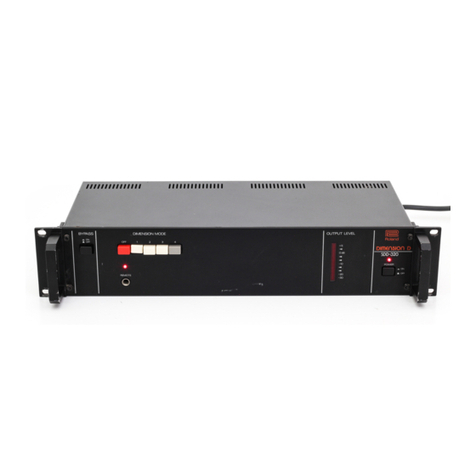
BYPASS Switch®
The BYPASS switch® makes direct
connections between the inputs and
outputs. This means that the POWER
switch ©may be left OFF when the
SDD-320isin the BYPASS mode.
©©
DIMENSION MODE Selectors @
Selects the dimension mode, MODE 1
produces the softest effect; MODE 4
produces the strongest effect. At OFF,
the sound passes through the SDD-320
without change.
REMOTE Jack®
For remote switching between the OFF
mode and the DIMENSION MODE
using afoot switch (Roland FS-1 or DP-
2; sold separately). To use, select a
DIMENSION MODE ©and use the
foot switch to switch between the
selected mode and normal sound.
•As an example of use: With an organ
as the input sound, play apoigression
of block chords and use ihe foot switch
so that some of the chords are
"straight" and others are "Dimension
D" chords. If the Roland DP-2 Pedal
Switch is used, instant changes can be
made even in very rapid passages. The
DIMENSION MODE IS in effect vv-ith [he
DP-2 depressed and OFF (normal
sound) when released.
EFFECT INDICATOR©
Lights when the DIMENSION MODE is
in effect,
•Works with both the REMOTE jack
©and the DIMENSION MODE se-
lectors ®,
OUTPUT LEVEL INDICATOR ©
Shows combined output level. (OdB
indication== +4dBm output),
•This indicator does not work when
the BYPASS switch ®is ON (BYPASS
MODE).
POWER Switch ©with pilot lamp
INPUT MODE Switch !A)
Selects the input mode. At MONO, left
input is disconnected and right input
serves both dimension channels.
INPUT Connectors g
Balanced inputs (13kfl; max.
+14dBm).
Pin assignments:
input:
Pin 1
Pin 2
Pin 3
shield (ground)
cold
hot
INPUT Jacks C
Unbalanced inputs (26kn: max,
+14dBm).
•Do not use the balanced and un-
balanced outputs simultaneously.
OUTPUT Connectors (0
Balanced output {Q(X)U; nom. level:
-t-4dBm). Pin assignments same as
INPUT connectors ©
OUTPUT Jacks £
Unbalanced output (6000; nom, level:
+4dBml.
•Do not use balanced and unbalanced
outputs simultaneously.
Note: If balanced inputs are used,
use balanced outputs and vice
versa. Do no! use balanced out-
puts when using unbalanced in-
puts, or unbalanced outputs when
using balanced inputs.
input:
