E+E Elektronik EE1900 User manual

BA_EE1900 // v1.1 // Modification rights reserved
User Manual
EE1900
HUMIDITY MODULE FOR
CLIMATE CHAMBERS

E+E Elektronik Ges.m.b.H. does not accept warranty and liability claims neither upon this publication nor in case
of improper treatment of the described products.
The document may contain technical inaccuracies and typographical errors. The content will be revised on a
regular basis. These changes will be implemented in later versions. The described products can be improved
and changed at any time without prior notice.
© Copyright E+E Elektronik Ges.m.b.H.
All rights reserved.
EMC note USA (FCC):
This equipment has been tested and found to comply with the limits for a Class A digital device, pursuant to part 15
of the FCC Rules. These limits are designed to provide reasonable protection against harmful interference when
the equipment is operated in a commercial environment. This equipment generates, uses, and can radiate radio
frequency energy and, if not installed and used in accordance with the instruction manual, may cause harmful
interference to radio communications. Operation of this equipment in a residential area is likely to cause harmful
interference in which case the user will be required to correct the interference at his own expense.
EMC note Canada (ICES-003):
CAN ICES-3 (A) / NMB-3 (A)

CONTENT
1 General .................................................................................................................................................4
1.1 Explanation of Symbols.................................................................................................................................4
1.2 Safety Instructions.........................................................................................................................................4
1.2.1 General Safety Instructions..................................................................................................................................4
1.2.2 Mounting, Start-up and Operation........................................................................................................................4
1.2.3 Intended Use........................................................................................................................................................5
1.3 Environmental Aspects..................................................................................................................................5
1.4 ESD Protection .............................................................................................................................................5
1.5 Scope of Supply ............................................................................................................................................5
2 Product Description ............................................................................................................................5
2.1 General..........................................................................................................................................................5
2.1.1 Sensing Probes....................................................................................................................................................6
2.1.2 Filter Caps............................................................................................................................................................6
2.2 Dimensions....................................................................................................................................................6
2.3 Installation .....................................................................................................................................................6
2.3.1 Electronics Board.................................................................................................................................................6
2.3.2 Sensing Probe .....................................................................................................................................................6
3 Electrical Connection..........................................................................................................................7
4 Setup and Configuration ....................................................................................................................8
4.1 Selection of the Output Signal.......................................................................................................................8
4.2 Selection of the Measurand - Output Scale ..................................................................................................8
4.3 Error Indication on the Analogue Output (NAMUR).......................................................................................9
5 Automatic Sensor ReCovery (ARC) ..................................................................................................9
6 Calibration / Adjustment................................................................................................................... 11
7 Self Diagnosis and Error Messages ................................................................................................ 11
8 Replacement Parts / Accessories....................................................................................................12
9 Technical Data ...................................................................................................................................12

4User Manual EE1900 Humidity Module for Climate Chambers
1 General
This user manual serves for ensuring proper handling and optimal functioning of the device. The user
manual shall be read before commissioning the equipment and it shall be provided to all staff involved
in transport, installation, operation, maintenance and repair.
The user manual may not be used for the purposes of competition without the written consent of E+E
Elektronik® and may not be forwarded to third parties. Copies may be made for internal purposes. All
information, technical data and diagrams included in these instructions are based on the information
available at the time of writing.
1.1 Explanation of Symbols
This symbol indicates safety information.
It is essential that all safety information is strictly observed. Failure to comply with this information can
lead to personal injuries or damage to property. E+E Elektronik® assumes no liability if this happens.
This symbol indicates instructions.
The instructions shall be observed in order to reach optimal performance of the device.
1.2 Safety Instructions
1.2.1 General Safety Instructions
• Avoid any unnecessary mechanical stress and inappropriate use.
• When replacing the filter cap make sure not to touch the sensing elements.
• For sensor cleaning and filter cap replacement please see “Cleaning instructions” at www.epluse.com.
• Installation, electrical connection, maintenance and commissioning shall be performed by
qualified personnel only.
1.2.2 Mounting, Start-up and Operation
The device has been produced under state of the art manufacturing conditions, has been thoroughly
tested and has left the factory fulfilling all safety criteria.
The manufacturer has taken all precautions to ensure safe operation of the device. The user must
ensure that the device is set up and installed in a manner that does not have a negative effect on its
safe use.
The user is responsible for observing all applicable safety guidelines, local and international, with
respect to safe installation and operation on the device. This user manual contains information and
warnings that must be observed by the user in order to ensure safe operation.
• Mounting, start-up, operation and maintenance of the device may be performed by qualified staff only.
Such staff must be authorized by the plant operator to carry out the mentioned activities.
• The qualified staff must have read and understood this user manual and must follow the instructions
contained within.
• All process and electrical connections shall be thoroughly checked by authorized staff before putting
the system into operation.
• Do not install or start-up a device supposed to be faulty. Make sure that such devices are not
accidentally used by marking them clearly as faulty.
• A faulty device may only be investigated and possibly repaired by qualified, trained and authorized
staff. If the fault cannot be fixed, the device shall be removed from the system.
• Service operations other than described in this user manual may only be performed by the
manufacturer.

5
User Manual EE1900 Humidity Module for Climate Chambers
1.2.3 Intended Use
The EE1900 humidity module is optimised for the measurement of relative humidity (RH) and dew point
temperature (Td) in climate chambers. The use of the EE1900 other than described in this manual is
not allowed.
The manufacturer cannot be held responsible for damages as a result of incorrect handling, installation
and maintenance of the device.
Unauthorized modifications of the product lead to loss of all warranty claims. The device may only be
powered with separated extra-low voltage (SELV).
Disclaimer
The manufacturer or his authorized agent can only be held liable in case of willful or gross negligence.
In any case, the scope of liability is limited to the corresponding amount of the order issued to the
manufacturer. The manufacturer assumes no liability for damages incurred due to failure to comply with
the applicable regulations, operating instructions or the operating conditions. Consequential damages
are excluded from the liability.
1.3 Environmental Aspects
Products from E+E Elektronik® are developed and manufactured observing of all relevant requirements
with respect to environment protection. Please observe local regulations for the device disposal.
For disposal, the individual components of the device must be separated according to local recycling
regulations. The electronics shall be disposed of correctly as electronics waste.
1.4 ESD Protection
The sensing elements and the electronics board are ESD (electrostatic discharge) sensitive
components of the device and must be handled as such. The failure to do so may damage the device
by electrostatic discharges when touching exposed sensitive components.
1.5 Scope of Supply
• EE1900 according to ordering guide
• Inspection certificate according to DIN EN 10204-3.1
2 Product Description
2.1 General
The sensing probe and the electronics of the EE1900 undergo the factory adjustment together and may
not be separated from each other. Do not cut, shorten or extend the probe cable.
The analogue output of EE1900 can be set to voltage or current with a slide switche on the electronics
board (see chapter 4.1).
The RH output is preferred for applications with rather uniform temperature distribution, while the Td
output is advisable in case of large T gradients in the environment.

6User Manual EE1900 Humidity Module for Climate Chambers
2.1.1 Sensing Probes
The EE1900 features a plastic (PPS) probe according to the order which can be employed over the
entire T range according to the technical data.
2.1.2 Filter Caps
The right choice of filter cap is very important for optimal performance under certain environment
conditions. Please see details in the “Accessories” data sheet at www.epluse.com/EE1900 or contact
the manufacturer’s representative for advice.
2.2 Dimensions
All values are given in mm / inch.
Ø 12 / 0.47
Probe length
(see ordering guide)
Cable length (see ordering guide)
Filter length
(see table below)
Ø 3.5 / 0.14
Ø 3.5 / 0.14
Fig. 1 Dimensions of EE1900
2.3 Installation
ESD handling regulations must be strictly observed.
2.3.1 Electronics Board
Hold the electronics boards only by the edges. Do not touch the components or their contacting.
2.3.2 Sensing Probe
Avoid touching the sensing head. The probe must be operated with the filter cap on at all times.
A clogged filter cap causes longer response time. For replacing the filter cap and cleaning the sensing
head please see the “Cleaning Instructions” at www.epluse.com/ee1900.
Do not touch the sensing elements!
Order code Filter length [mm/inch]
F9 39 / 1.54
F4 33 / 1.30
no code 33 / 1.30
F12 33 / 1.30
7
User Manual EE1900 Humidity Module for Climate Chambers
For accurate measurement results it is of paramount importance to avoid temperature gradients along
the sensing probe. Whenever possible, install the entire probe in the environment to monitor. If the
probe is installed into a partition wall, the probe‘s backend shall be isolated thermally.
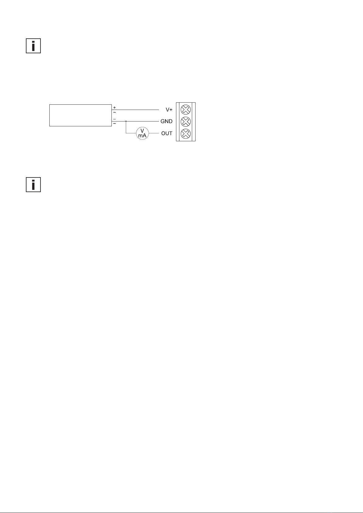
3 Electrical Connection
Supply
Fig. 2
Power supply
15 - 35 V DC
17 - 29 V AC
Connection supply and outputs
Use only power supply units according to EN 61140, protection class III (EU) and protection class II
(North America).
For performance according to the specifications, the electronics board must be properly grounded,
see chapter 4 (No. 9 “Grounding“ - Fig. 3).
8User Manual EE1900 Humidity Module for Climate Chambers
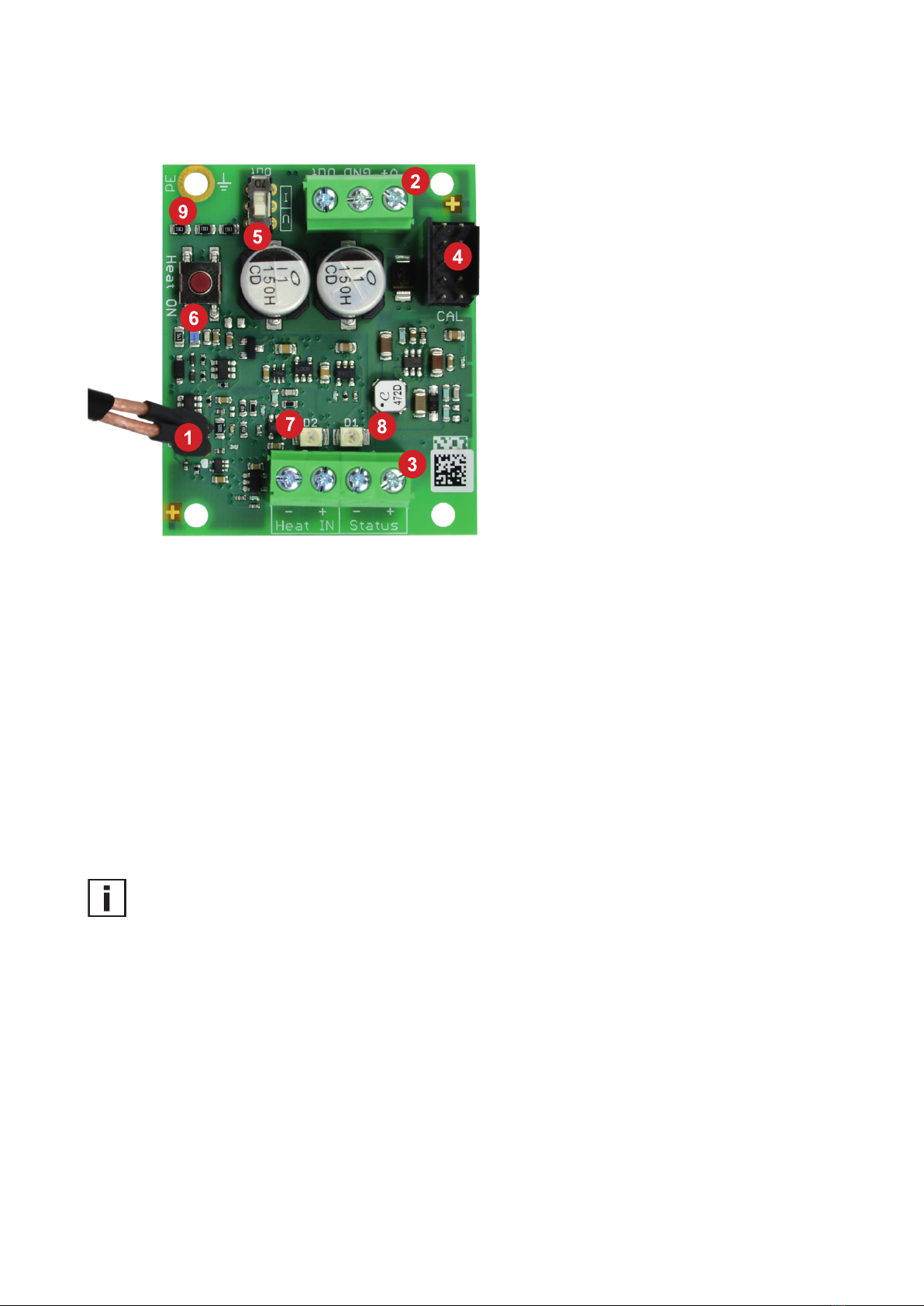
4 Setup and Configuration
1. Probe connection
2. Terminals for supply and output signal
3. Terminals for ARC external triggering
(Heat IN) and status information (Status)
4. Configuration interface
5. Slide switch for output signal selection
(voltage / current)
6. Manual trigger for ARC
7. Status LED (green)
8. Error indication LED (red)
9. Grounding
Fig. 3 Electronics board
4.1 Selection of the Output Signal
Use the slide switch (No. 5 - Fig. 3) to select between current and voltage output.
• When switching from original voltage output to current output, the output becomes
0 - 20 mA = 0…100% RH and error indication according NAMUR (see chapter 4.3) is disabled.
• When switching from original current output to voltage output, the output becomes
0 - 10 V = 0…100% RH and error indication according NAMUR (see chapter 4.3) is disabled.
After switching the output between voltage and current with the slide switch, the scaling of the output
can be set using the E+E Product Configuration Software (see chapter 4.2).
Important:
• After changing the factory setup (output signal and/or output scale) the packaging label loses its
validity; it does not match any longer the device setup.
• The factory setup restore function of EE-PCS reestablishes the original adjustment/calibration of the
device, but does not affect the user setup for output signal and output scale.
4.2 Selection of the Measurand - Output Scale
The selection between R, Td and Tf (frost point temperature) on the analog output, as well as the
scaling of the output can be performed via the configuration interface with the EE-PCS Product Configu-
ration Software, free download from www.epluse.com/configurator. Use the optional configuration cable
HA011017 to connect the EE1900 to the USB port of the PC.
9
User Manual EE1900 Humidity Module for Climate Chambers
4.3 Error Indication on the Analogue Output (NAMUR)
The EE1900 features an error indication on the analogue output according to NAMUR
recommendations. A device failure is indicated by 11 V in case of voltage output and by 21 mA
in case of current output.
Important:
Upon delivery the NAMUR error indication is disabled. It can be enabled with the free EE-PCS Product
Configuration Software.
5 Automatic Sensor ReCovery (ARC)
Certain chemical pollution may lead to drift of the sensing element. Using the sensor recovery function,
the contamination is removed by a controlled heating of the sensor. After the heating process, the sensor
quickly returns to normal measuring conditions (refer to Fig. 5).
Start:
The ARC can be started either manually by pressing the “Sensor Recovery” button (No. 6 - Fig. 3) for
min. 3 seconds or automatically by applying a voltage of 5 - 30 V DC to the potential free input (No. 3
“Heat IN“ - Fig. 3) for at least 3 seconds.
Abortion:
To cancel the ARC process, the same procedure is valid as to starting it: pressing the “Sensor
Recovery” button (No. 6 - Fig. 3) or a voltage of 5 - 30 V DC at the “Heat IN“ interface for min. 3
seconds.
Duration:
A sensor recovery cycle takes around 23 minutes, of which 20 minutes heat-up time, followed by 3
minutes cooling time. The cooling time is necessary also in case the ARC process is cancelled.
Current consumption in ARC mode
Supply Consumption
15 V DC ~120 mA (max.)
24 V DC ~80 mA (max.)
35 V DC ~55 mA (max.)
17 V AC ~210 mArms (max.)
24 V AC ~160 mArms (max.)
29 V AC ~140 mArms (max.)
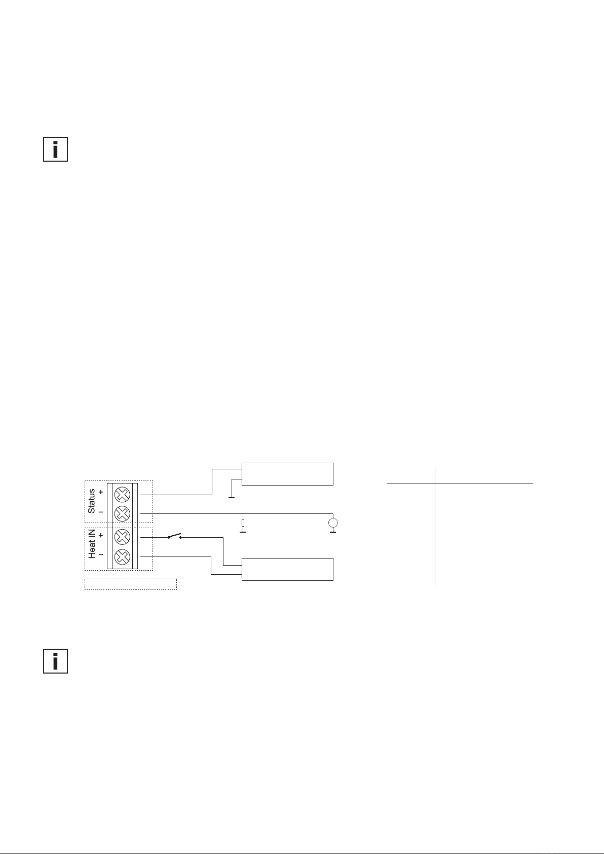
+
GND
Power supply
5 - 30 V DC
+
GND
GND
GND
Pulldown: ≤100 k
Power supply
5 - 30 V DC
in
out ARCStatus
V
Galvanically separated input/output
Fig. 4 ARC trigger and status connection
Important:
ARC can only be started if RH < 85%.

10 User Manual EE1900 Humidity Module for Climate Chambers
Fig. 5
T [°C (°F)]
160 (320)
cooling time min. 3 min
freezing period of output signals
T [min]
ambient temperature
start automatic
recovery ARC
heating time 20 min
U [ V DC ]
5 - 30
T [min]
U [ V DC ]
5 - 30
T [min]
min. 3 s
ARC T Profile
ARC Status
Heat IN
ARC Chart
During the sensor recovery process, the output is frozen at the last measured value before triggering
the sensor recovery.
The ARC mode is indicated by the closed contact at the optocoupler output (No. 3 „Status“ - Fig. 3)
and by the red LED flashing very quickly. The optocoupler output thus indicates wether the data on
the analogue output is up-to-date (during normal measurement) or frozen (during the sensor recovery
process).
An efficient sensor recovery requires a certain sensor temperature. In case of strong air flow at the
sensing head (for instance more than 6 m/s with the stainless steel grid filter), the required sensor
temperature might not be reached. In such a case, the heating process is automatically interrupted
after 2 minutes.
11
User Manual EE1900 Humidity Module for Climate Chambers
6 Calibration / Adjustment
Definition of terms:
Calibration
The calibration documents the accuracy of a measurement device. The device under test (specimen) is
compared with the reference and the deviations are documented in a calibration certificate. During the
calibration, the specimen is not changed or improved in any way.
Adjustment
The adjustment improves the measurement accuracy of a device. The specimen is compared with the
reference and brought in line with it. An adjustment can be followed by a calibration which documents
the accuracy of the adjusted specimen.
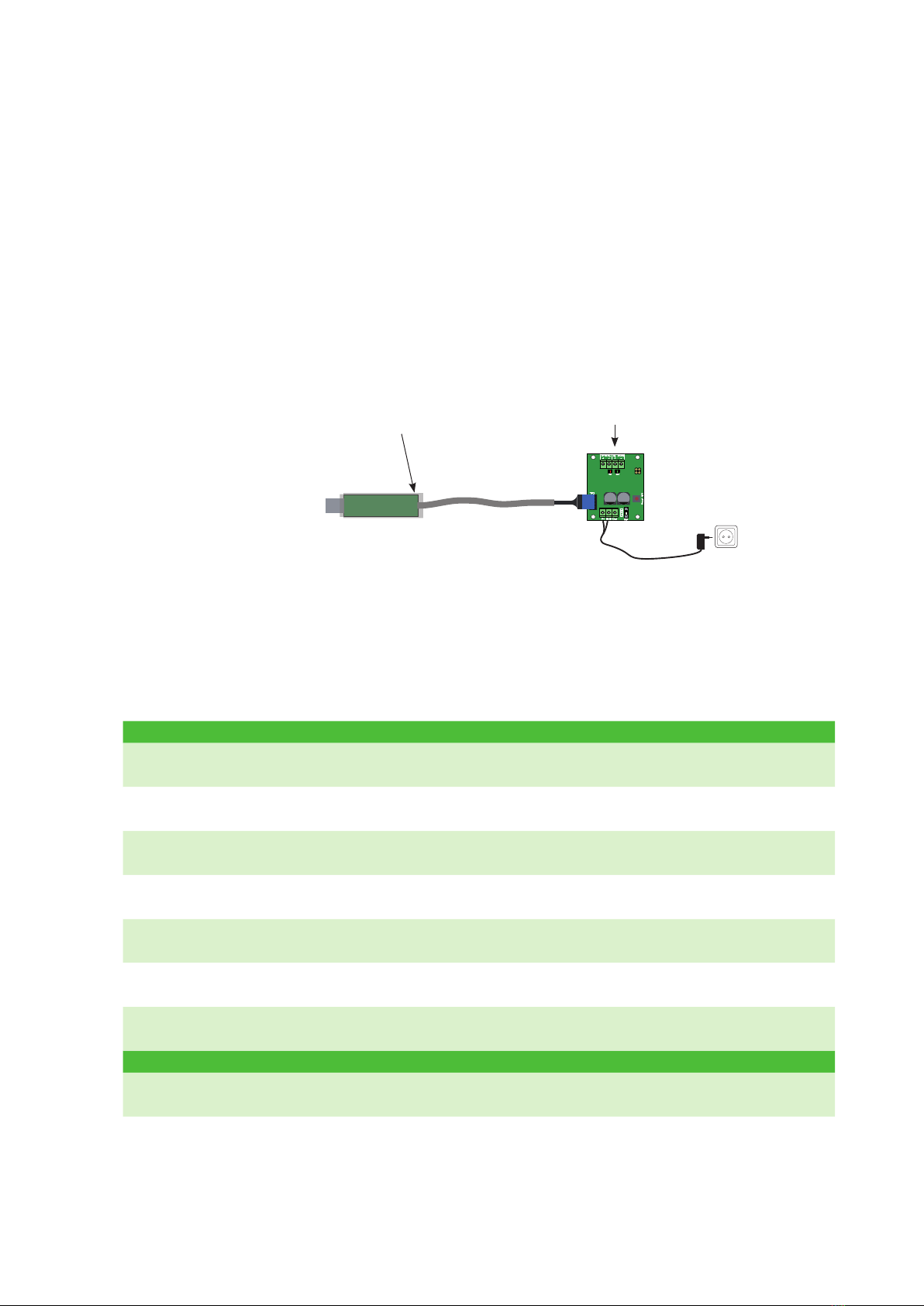
The adjustment of EE1900 can be performed with the EE-PCS Product Configuration Software, free
download from www.epluse.com/configurator.
Fig. 6 EE1900 Adjustment and Configuration
PC
HA011017 EE1900
The adjustment shall be performed for the RH output against an appropriate RH reference.
See “Calibration Kit - User Guide“ at www.epluse.com/ee1900.
7 Self Diagnosis and Error Messages
Feedback module Meaning Action
Green and red LED
on for about 1 sec.
Acknowledgment for ARC
start / stop
The ARC mode is either started or stopped. If the sensor
is in the ARC mode the red LED flashes very fast.
Green LED flashing /
Red LED off Normal measuring mode -
Red LED on Electronics failure Contact the E+E representative.
Red LED flashes
(1Hz)
Probe is not properly
connected or damaged Contact the E+E representative.
Red LED flashes very
fast (5 Hz) ARC mode is active Wait until the ARC cycle is finished,
or interrupt the ARC cycle
Optocoupler closed humidity output is frozen /
ARC active
Wait until the ARC cycle ist finished.
Check the red LED.
Optocoupler open Normal measuring mode /
ARC inactive -
Namur (Disabled by default)
21 mA / 11 V An error has occurred Contact the E+E representative.

12 User Manual EE1900 Humidity Module for Climate Chambers
8 Replacement Parts / Accessories
See data sheet “Accessories” at www.epluse.com/EE1900
Description Order code
- Filter caps HA0101xx
- Stainless steel grid HA010109
- Stainless steel sintered HA010117
- PTFE HA010105
- H2O2HA010115
- Mounting flange stainless steel HA010201
- Mounting flange plastic HA010202
- Wall mounting clip stainless steel HA010225
- Wall mounting clip plastic -35...105 °C (-31...221 °F) HA010211
- Configuration cable with USB adapter HA011017
-Humidity calibration kit see data sheet “Humidity calibration kit“
- Protection cap for Ø12 mm (0.47") probe HA010783
9 Technical Data
Sensing element HMC01
Measurands
Relative humidity (RH)
Working range 0…100% RH
Accuracy1) (incl. hysteresis, non-linearity and repeatability)
-20...40 °C (-4...104 °F) ± 2% RH (≤90% RH) / ± 2.5% RH (>90% RH)
-40...180 °C (-40...356 °F) ± 2.5% RH (≤90% RH) / ± 3.5% RH (>90% RH)
Dew point (Td)
Working range -20...80 °C (-4...176 °F)
Accuracy ± 2 °C (± 3.6 °F) for | Tambient - Td | < 20 °C (36 °F)
General
Response time RH t10/90 at 20°C (68 °F), typ. 15 s with stainless steel grid filter2)
Output signal 0 - 1 / 5 / 10 V -1 mA < IL< 1 mA
0 / 4 - 20 mA (3 wire) RL < 500 Ω
ARC status signal Optocoupler, open/closed
Supply voltage 15 - 35 V DC and 17 - 29 V AC
Current consumption
for DC supply < 32 mA
for AC supply < 60 mArms
Working range electronics -40…60 °C (-40...140 °F) / 0...90% RH non-condensing
Working range probe -70...180 °C (-94...356 °F) / 0...100 % RH
Storage conditions -40…60 °C (-40...140 °F) / 0...90% RH non-condensing
Electrical connection Screw terminals up to max. 1,5 mm² (AWG 16)
Electromagnetic compatibility Component for OEM equipment tested according to
EN 61000-4-3 and EN 61000-4-6
1) The accuracy statement includes the uncertainty of the factory calibration with an enhancement factor k=2 (2-times standard deviation). The accuracy was
calculated in accordance with EA-4/02 and with regard to GUM (Guide to the Expression of Uncertainty in Measurement).
2) Other filters see data sheet “Accessories”.

HEADQUARTERS
E+E Elektronik Ges.m.b.H.
Langwiesen 7
4209 Engerwitzdorf
Austria
Tel.: +43 7235 605-0
E-mail: [email protected]
Web: www.epluse.com
SUBSIDIARIES
E+E Elektronik China
18F, Kaidi Financial Building,
No.1088 XiangYin Road
200433 Shanghai
Tel.: +86 21 6117 6129
E-mail: [email protected]
E+E Elektronik France
Le Norly III, 136 chemin du Moulin
69130 Ecully
Tel.: +33 4 74 72 35 82
E-mail: [email protected]
E+E Elektronik Germany
Schöne Aussicht 8 C
61348 Bad Homburg
Tel.: +49 6172 13881-0
E-mail: [email protected]
E+E Elektronik Italy
Via Alghero 17/19
20128 Milano (MI)
Tel.: +39 02 2707 86 36
E-mail: [email protected]
E+E Elektronik Korea
Suite 2001, Heungdeok IT
Valley Towerdong, 13,
Heungdeok 1-ro, Giheung-gu
16954 Yongin-si, Gyeonggi-do
Tel.: +82 31 732 6050
E-mail: [email protected]
E+E Elektronik USA
333 East State Parkway
Schaumburg, IL 60173
Tel.: +1 847 490 0520
E-mail: [email protected]
Table of contents
Other E+E Elektronik Control Unit manuals


