PIETRO FIORENTINI DILOCK 507 User manual

EN
TECHINICAL MANUAL
Slam Shut Valves
DILOCK 507/512/106

2
MT 237 – EN ed.2015 (Rev.A)
EN
DILOCK: Basic version
INLET PRESSURE
CONTROL PRESSURE
DILOCK 507/512/106

3
MT 237 –EN ed.2015 (Rev.A)
GENERAL WARNINGS
The equipment described in this manual is a device subject to pressure installed in systems under pressure.
The involved equipment is usually integrated in systems conveying flammable gases (e.g. natural gas).
WARNINGS FOR THE OPERATORS
Before performing the installation, commissioning or maintenance, the operators must:
go through the safety provisions applicable to the installation where they have to operate;
obtain the necessary authorizations to operate, when required;
be equipped with the necessary personal protective equipment (helmet, goggles, etc.)
make sure that the area in which they have to operate is equipped with the required collective protections as well as with the
necessary safety signs.
PACKAGING / TRANSPORT / STORAGE
The packaging materials used for transporting the equipment and the related spare parts have been designed and manufactured to avoid
damages during normal transport, storage, and related handling. Therefore, the equipment and spare parts must be kept in their respective
original packages till their installation in the final destination site. When the packages are opened, it is necessary to verify the integrity of the
materials therein contained. In case of damages, report the detected damages to the suppliers preserving the original package to allow the
performance of necessary inspections.
The storage of the equipment, even after their use, must occur in suitable places, free of moisture and away from sources of light and heat,
within the limits stated on the rating plate
HANDLING
The handling of the equipment and its components must be performed after having established that the lifting means are suitable for the
loads to be lifted (lifting capacity and functionality) in order to avoid bumps, impacts and local stresses.
When necessary, the handling of the equipment must be performed using the lifting points foreseen on the equipment itself. The use of
motorized means is reserved to authorized personnel only.
INSTALLATION
The installation of the pressure equipment must occur in compliance with the provisions (laws or regulations) in force in the place of
installation.
In detail, natural gas plants must show features complying with the law provisions or regulations in force in the place of installation or at
least complying with the standards EN 12186 or EN 12279. The installation in compliance with such standards minimizes the risk of fire and
the formation of potentially hazardous atmospheres.
The equipment is not provided with internal pressure limitation devices; therefore, it must be installed making sure that the operating
pressure of the assembly in which it is installed does not exceed the value of the allowable maximum pressure (PS).
The user shall, therefore, when he/she deems it necessary, provide for the installation of suitable pressure limitation systems on the
assembly; Moreover, the user shall equip the plant with suitable relief or drain systems in order to be able to discharge the pressure and the
fluid contained in the plant before proceeding with any inspection and maintenance activity.
Should the installation of the equipment require the installation of compression fittings on site, these latter have to be installed following the
instructions provided by the manufacturer of the fittings. The selection of the fittings must be compatible with the use specified for the
equipment and with the plant specifications, when foreseen.
COMMISSIONING
The commissioning must be carried out by suitably trained personnel.
During the commissioning, the personnel not strictly necessary must be kept away and the limited access area must be properly marked
(signs, barriers, etc.).
Verify that the equipment calibrations are the ones required. If necessary, restore the required values for the same as provided for later on
in this manual.
During the commissioning, the risks determined by any discharges to the atmosphere of flammable or noxious gases must be assessed.
In case of installation on natural gas distribution networks, it is necessary to consider the risk of formation of a (gas/air) explosive mix within
the piping.
COMPLIANCE WITH DIRECTIVE 97/23/EC (PED)
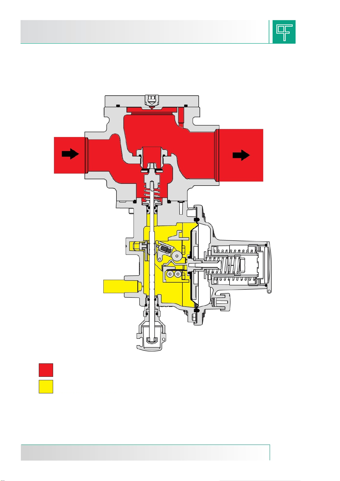
The slam-shut valve Dilock 507 / 512 / 106, as standalone equipment, is classified pursuant to the Directive 97/23/EC (PED) as:
Pressure accessory when it is forecast to trip in case of pressure increase;
Safety accessory, pursuant to paragraph 2.1.3 of Article 1 of the same Directive, when it is forecast to trip in case of both
pressure increase and decrease.

4
MT 237 –EN ed.2015 (Rev.A)
1.0 INTRODUCTION
This manual aims at supplying essential information on the installation, commissioning, disassembly, re-assembly, and maintenance of
the slam-shut valves DILOCK 507 / 512 / 106.
Moreover, it is deemed suitable to provide the reader with a brief description of the main features of the regulator and its accessories.
1.1 MAIN FEATURES
This slam-shut valve is a device that immediately blocks the gas flow, if - due to any failures - the pressure inside a piping reaches the
preset value for its tripping.
The main features of this device are:
Design pressure PS: up to 20 bar
Operating temperature: -20 °C ÷ + 60 °C;
Ambient temperature: -20 °C ÷ + 60 °C;
Tripping due to pressure increase and/or decrease
Tripping range due to pressure increase: 30 to 5500 mbar
Tripping range due to pressure decrease: 6 to 3500 mbar
Internal by-pass device
Suitable for operation with gaseous, non-corrosive, previously treated and filtered fluids
Accuracy class AG: up to ±5% on the calibration value for pressure increase (depending on the calibration pressure range); up to
±20% for pressure decrease (according to the calibration pressure)
1.2 OPERATION OF THE SLAM-SHUT VALVE
Figure 1: Slam-Shut Device LA
The slam-shut valve (fig. 1), tripping in case of minimum and maximum pressure, is essentially made up of an obturator mounted on a stem,
a release lever mechanism, a control head and a manual restoration system. In the chamber Cof the control head, the pressure to be
controlled Pd acts on the membrane 536, which is integral with the shaft provided with cam 535.
The load of the pressure Pd on the membrane is opposed by the springs 546 and 547, which cause, respectively, the tripping due to
increase or decrease in the pressure. The calibration of the device is performed by acting on the ring nuts 548 and 549. A clockwise rotation
of the ring nuts results in an increase in the tripping value; vice versa in case of counter-clockwise rotation.
In case of tripping due to pressure increase, when the pressure Pd exceeds the calibration value, the load on the membrane 536 increases
until it overcomes the resistance of the spring 547. This causes the movement of the shaft 535, which - by means of the cam - moves the
touch probe 509 thus releasing the lever mechanism. In this way, the stem 517 is freed and the obturator 526 is made to close by the spring
525.

5
MT 237 –EN ed.2015 (Rev.A)
The tripping due to pressure decrease instead occurs as follows.
As long as the pressure value Pd remains above the calibration load of the spring 546, the spring support 544 remains leaning on the
support 545.
If the pressure Pd decreases below the pre-set value, the spring 546 makes the support 544 and consequently the shaft 535 move.
Consequently, the cam moves the touch probe 509 causing the release of the lever mechanism.
The restoration of the block occurs by pulling the bushing 531 until the lever mechanism is coupled again.
During the first stage of the manoeuvre, it is necessary to wait until the upstream pressure passes downstream of the obturator - through
the internal bypass - and balances it. After restoring the slamshut valve to its open position, bushing 518has to be press-fit into its seat.
The opening or closing status of the slam-shut valve is detectable from outside by observing the position of the colored cap 531 through the
plug 532.
1.3 CALIBRATION SPRINGS
Table 1.1 shows the calibration ranges of the different available springs.
FEATURES OF THE SPRINGS FOR LA/BP SLAM-SHUT VALVES
Code
Colour
De
Lo
d
Calibration range (mbar)
Tripping due to maximum pressure
64470112RO
RED
34
43
2.2
30÷49
64470115GR
GREY
34
42
2.8
50÷180
Tripping due to minimum pressure
64470024BI
WHITE
15
45
1.3
6÷60
De = Ø external d = Ø wire Lo = Length
FEATURES OF THE SPRINGS FOR LA/MP SLAM-SHUT VALVES
Code
Colour
De
Lo
d
Calibration range (mbar)
Tripping due to maximum pressure
64470115GR
GREY
34
42
2.8
140÷179
64470116GI
YELLOW
34
40
3.2
180÷279
64470051BI
WHITE
34
50
3.2
280÷450
Tripping due to minimum pressure
64470024BI
WHITE
15
45
1.3
10÷59
64470038GI
YELLOW
15
40
2
60÷240
De = Ø external d = Ø wire Lo = Length
FEATURES OF THE SPRINGS FOR LA/TR SLAM-SHUT VALVES
Code
Colour
De
Lo
d
Calibration range (mbar)
Tripping due to maximum pressure
64470116GI
YELLOW
34
40
3.2
250÷549
64470051BI
WHITE
34
50
3.2
550÷849
64470057BL
BLUE
34
50
3.5
850÷1399
64470058AR
ORANGE
34
50
4
1400÷2499
64470059AZ
LIGHTBLUE
34
50
4.5
2500÷3999
64470060NE
BLACK
34
48
5
4000÷5500
Tripping due to minimum pressure
64470038GI
YELLOW
15
40
2
100÷499
64470045MA
BROWN
15.3
41
2.4
500÷999
64470046BL
BLUE
15
40
3
1000÷1999
64470149NE
BLACK
15
43
3.2
2000÷3500
De = Ø external d = Ø wire Lo = Length

6
MT 237 –EN ed.2015 (Rev.A)
2.0 INSTALLATION
2.1 GENERAL
Before installing the valve, it is necessary to make sure that:
it can be inserted in the forecast space and is sufficiently accessible for performing the following maintenance operations (see
overall dimensions in table 2.1);
the inlet and outlet pipings are on the same level and are able to support the valve weight (see weights table 2.2);
the inlet/outlet connections of the piping are parallel;
the inlet/outlet connections of the regulator are clean and the regulator itself has not been subject to any damages during
transport;
the inlet piping has been cleaned in order to remove any residual impurities such as welding scraps, sand, paint residues, water,
etc.
The arrangement normally forecast is the one shown in fig. 2.
Figure 2
Table 2.1: Overall dimensions in mm (fig. 3)
Code
DN
NPS
A
B
C
D
E
N
DILOCK507
25x25
1”x1”
100
62
182
92
161
Rp 1/4”
DILOCK512
25x40
1”x1”1/2
110
65
188
92
161
Rp 1/4”
DILOCK106
32x32
40x40
50x50
1”1/4x1”1/4
1”1/2x1”1/2
2”x2”
152
198
78
162
//
Rp 1/4”
DILOCK106
65x65
80x80
100x100
2”1/2x2”1/2
3”x3”
4”x4”
354
287
103
245
//
Rp 1/4”
Table 2.2: Weights in KGF
Code
DN
NPS
KGF
DILOCK507
25x25
1”x1”
2.8
DILOCK512
25x40
1”x1”1/2
3
DILOCK106
32x32
40x40
50x50
1”1/4x1”1/4
1”1/2x1”1/2
2”x2”
2
DILOCK106
65x65
80x80
100x100
2”1/2x2”1/2
3”x3”
4”x4”
8.8

7
MT 237 –EN ed.2015 (Rev.A)
Figure 3: Overall dimensions

8
MT 237 –EN ed.2015 (Rev.A)
2.2 CONNECTING THE EQUIPMENT
The valve has to be installed on the line with the arrow on the body positioned in the gas flow direction.
The connections between the equipment and the piping have to be carried out using a stainless steel or copper pipe, having a minimum
internal diameter of 8 mm.
To obtain the correct operation, it is essential that the downstream sensing line is connected to a straight section of the piping itself,
having a length equal to 4 times the piping diameter (therefore, without any possible signal turbulence), as well as that the maximum gas
speed at the sensing point does not exceed 30 m/sec.
In order to prevent impurities and condensation to deposit in the pressure sensing tubes, it is advisable to provide for the following:
the tubes shall always be positioned on a descending slope towards the connection of the outlet piping with a slope of about 5 -
10%;
tube branch connections shall always be welded on the upper part of the piping itself and the hole on the piping shall not show
any burrs or projections towards the internal side.
To avoid breakages or unwanted deformations, it is recommended to provide for the following:
the equipment shall be installed pursuant to the regulations in force and the good practice
that shall not be any external loads acting on the device
the equipment shall be provided with adequate protection and grounding means to protect it against stray currents and
electrostatic potential differentials
the equipment shall be used within the limits set on the rating plate
The most frequent types of installation on a gas pressure reduction line of the valve DILOCK are shown in the figures 4 and 5.
Installation of the valve on a piping segment
Figure 4: Installation diagram
Installation of the valve on a gas pressure reduction line as safety in case of fault of the pressure regulator
Figure 5: Installation diagram
Slam-shut
valve
Sensing line
Pressure gauge
Relief valve
On-off valve
Pressure gauge
On-off valve

9
MT 237 –EN ed.2015 (Rev.A)
3.0 ACCESSORIES
3.1 "PUSH" THREE-WAY SWITCH VALVE
The "push" valve is a three-way switch valve with spring return. With the knob set to the normal operation position, the ways A and B are
angle communicating; while way C is excluded (fig. 6).
Figure 6
With the knob pressed downwards, in "check" position, the ways A and C are communicating, while way B is excluded (fig. 7). When the
knob is released, the communication between the ways A and B is automatically restored due to the tripping of the spring D.
Figure 7
This valve is usually installed in the sensing lines of safety devices against pressure increase and/or decrease (SAV or SBV) in order to
be able to verify their calibrations in a very short time without disconnecting the sensing pipe during the periodic checks.
The peculiarity of this lies in the fact that, during normal operation, the pressure switch head receives the signal of the pressure to be kept
monitored through the ways A and B. In the control phase, the head receives a signal from an external auxiliary controlled pressure from
way A and C. Once the knob returns to its normal operation position, the connection between the environment with the pressure to be
monitored and the head of the safety device is restored automatically, thus avoiding the on/off switching of the device, which may happen
due to a sheer oversight, if the three-way valve would be of the normal type with manual operation. In other words, the "push" device is a
second safety device, which assures the non-exclusion of the main safety device and allows its periodical check.

10
MT 237 –EN ed.2015 (Rev.A)
4.0 COMMISSIONING
4.1 GENERAL
After the installation, verify that the on/off valves at inlet and outlet, any available bypass, and the relief valve are closed.
Before commissioning, it is recommended to verify that the use conditions do meet the features of the equipment.
Such features are identified by the corresponding symbols on the rating plates present on the equipment itself (fig. 13).
It is recommended to enable the opening and closing valves very slowly. Too fast manoeuvres may damage the device.
EQUIPMENT RATING PLATES
Figure 8: Equipment rating plate
Here below there is the list of the symbols used together with their meaning.
= Compliance with Directive 97/23/EC (PED)
TS= allowable temperature range within which it is possible to use the valve
FLUID= type of fluid for which the device was developed
AG = block tripping accuracy.
PS= maximum allowable pressure that can be born under safety conditions by the device body structure.
Pumax= maximum operation pressure at device inlet.
DNi= type of inlet connection to the device
DNu= type of outlet connection from the device
Class= allowable temperature range within which it is possible to use the valve
IS= type of test performed on the device
Wdo = overpressure tripping range of the slam-shut valve, which can be obtained by using the various calibration springs listed in the
tables.
Wdso = overpressure tripping range of the slam-shut valve, which can be obtained by using the calibration spring mounted during final
testing.
Wdu = underpressure tripping range of the slam-shut valve, which can be obtained by using the various calibration springs listed in the
tables.
Wdsu = underpressure tripping range of the slam-shut valve, which can be obtained by using the calibration spring mounted during final
testing.
OPSO= tripping value of the slam-shut valve due to pressure increase
UPSO= tripping value of the slam-shut valve due to pressure decrease

11
MT 237 –EN ed.2015 (Rev.A)
4.2 GAS FEEDING, CHECK OF EXTERNAL TIGHTNESS AND CALIBRATIONS
Pressure feeding to the equipment shall be performed very slowly. Where no specific speed procedure is implemented, it is recommended
to keep the gas speed in the feeding piping under a value of 5 m/sec, during the pressure feeding phase.
In order to prevent the equipment from being damaged, the following shall be absolutely avoided:
Pressurization through a valve positioned downstream of the equipment itself.
Depressurization through a valve positioned at inlet of the equipment itself.
The external tightness is assured when, by applying a foam medium on the element under pressure, no bubbles are produced.
Usually, the equipment is supplied already calibrated to the requested value.
Moreover, it may happen that due to several reasons (e.g. vibrations during transport) the calibrations may be subject to slight changes,
though remaining within the range of the values allowed by the springs used. Therefore, it is advisable to verify the calibrations according to
the procedures outlined here below.
Before commissioning the device, it is necessary to verify that all on/off valves (inlet, outlet, and bypass - if any) are closed and
that the gas has such a temperature as not to create malfunctions.
4.3 EXTERNAL TIGHTNESS AND CALIBRATIONS CHECK
A. For the slam-shut devices connected to the downstream piping through the "push" three-way switch valve, proceed as follows:
Figure 9
1. Connect a controlled auxiliary pressure to the "push" valve (way C);
2. Stabilize this pressure at the calibration value set for the regulator;
3. Completely press the knob 1 of the "push" three-way valve;
4. Restore the slam-shut device by means of the suitable bushing;
5. Keep the knob 1 pressed and:
For safety devices tripping in case of maximum pressure: slowly increase the auxiliary pressure and verify the tripping
value. If necessary, increase the tripping value by rotating clockwise the adjustment ring nut 549; rotate it counter-
clockwise to decrease the tripping value.
For safety devices tripping in case of pressure increase and decrease: slowly increase the auxiliary pressure and
record the tripping value. Restore the pressure to the calibration value of the regulator and perform the block
restoration operation. Check the tripping due to pressure decrease by slowly reducing the auxiliary pressure. If
necessary, increase the values for tripping in case of pressure increase or decrease by turning clockwise the ring
nuts 549 or 548, respectively. Proceed inversely to decrease the tripping values.
Make sure that the operation is correct by repeating the procedure for at least 2-3 times
6. Disconnect the controlled auxiliary pressure from way C;

12
MT 237 –EN ed.2015 (Rev.A)
B. For devices not equipped with "push" valve, it is recommended to separately connect the control head to a controlled auxiliary
pressure and repeat the operations described above.
Figure 10
CAUTION
Attheendoftheprocedure,connectthecontrolhead
againto thepressuresensingpointdownstream.
NB.: It is recommended to repeat the tripping tests at least every 6 months.
At the end of the slam-shut device check operations, and referring to fig. 4 or fig. 5 proceed as follows:
Make sure that the slam-shut device is in closed position;
Open the inlet on/off valve V1;
Very slowly open the slam-shut valve, by pulling the proper bushing;
Partially open the relief valve 6 on the outlet piping;
Using the pressure gauge 5, check that the downstream pressure has the wished calibration value for the regulator. Should this
not be the case, adjust the calibration by acting on the inner ring nut, turning it clockwise to increase and counter-clockwise to
decrease;
Close the relief valve 6 and check the lockup pressure value;
With a foamy substance, check the tightness of all the joints present between the on/off valves V1 and V2;
Very slowly open the outlet on/off valve V2 until reaching the complete filling of the piping;

13
MT 237 –EN ed.2015 (Rev.A)
5.0 TROUBLESHOOTING
Some of the operational anomalies that may occur from time to time, are described below. These are phenomena linked to the gas
conditions, as well as, of course, to the natural aging and wear of the materials.
Please note that all interventions on the equipment must be performed by technically qualified personnel having suitable knowledge
on the matter.
The tampering and improper use of the equipment by non-qualified personnel relieves Pietro Fiorentini SpA from any liability
whatsoever.
5.1 ANOMALIES OF THE SLAM-SHUT VALVE DILOCK…
Table 5.1 describes the possible malfunctions that may occur over time
INCONVENIENCE
POSSIBLE CAUSES
INTERVENTION
The blocking obturator does not close
Breakage of the membrane [536] of
the measuring head
Replacement
Leak from the slam-shut valve
obturator
Obturator gasket [526] deteriorated
Replacement
Obturator seat eroded or scratched
Replacement
Wrong release pressure
Wrong calibration of the min. and/or
max. spring
Perform the calibration again by
acting on the ring nuts [549] and/or
[549]
Lever mechanisms subject to friction
Change the box containing the entire
assembly
It is not possible to perform restoration
The cause that led to the pressure
increase or decrease downstream
does persist
Let downstream pressure drop or
increase it
Broken or splintered lever
mechanisms
Change the standard box containing
the assembly outside the regulator
NB. If the slam-shut valve tripped, first of all close the inlet and outlet valves (V1 and V2) of the line and discharge the pressure.
Solve the causes, which led to the tripping before restoring the equipment.
In case of malfunctions, if there is no qualified personnel available for the specific intervention, contact our customer service centre nearest
to you. For any further information, refer to our SATRI service at our plant in Arcugnano (VI), Italy.

14
MT 237 –EN ed.2015 (Rev.A)
6.0 MAINTENANCE
6.1 GENERAL
Maintenance, inspection and operation activities have to be carried out in compliance with the regulations in force on the matter in the place
of installation of the equipment (type and frequency). Before performing any kind of intervention, it is important to ensure that the slam-shut
valve has been closed, that the inlet & outlet isolating valves have been closed and that all of the pressure has been discharged from the
piping between the slam-shut valve and those isolating valves. Maintenance interventions are strictly bound to the quality of the conveyed
gas (impurities, humidity, gasoline, corrosive substances) and to the filtration efficiency.
Therefore, it is always recommended to perform preventive maintenance interventions whose periodicity shall be determined according to
the following aspects, unless specified by regulations already in force:
The quality of the conveyed gas;
The status of cleaning and preservation of the piping upstream of the regulator: as a rule, for example, after the first start of the
plants, more frequent maintenance interventions are required due to the uncertain internal cleanliness of the piping;
The reliability level required by the reduction plant.
Before starting disassembling the equipment make sure:
To have a series of original spare parts available. Spare parts shall be original spare parts by Pietro Fiorentini bearing in mind
that the most important parts such as membranes are marked.
To have a set of tools as shown in table 6.4.
For proper maintenance, the recommended spare parts are unequivocally identified by tags indicating:
The SS layout drawing number of the equipment in which they can be used;
The position given on the SS layout drawing of the equipment; it is suggested to replace all rubber parts; for this purpose, use the
suitable spare part kit available on Pietro Fiorentini website.
NB. The use of non-original parts relieves Pietro Fiorentini S.p.A. from any liability whatsoever.
Pay attention to discharging vents & drains to a safe area during the depressurization activities. To avoid risks related to the formation of
sparks due to particles of impurities inside the discharge lines, it is recommended to keep fluid speed lower than 5 m/sec.
Moreover, for those parts that can be positioned or oriented in more than one way during re-assembly, it is suggested to add reference
marks on those parts before disassembling.
Finally, it shall be underlined that the O-rings and the sliding mechanical parts (stems, etc.) have to be lubricated before reassembling them,
by applying a thin layer of silicone grease. Before commissioning, it is necessary to verify the external tightness of the equipment at a
suitable pressure for assuring the absence of external leaks.
The internal tightness of the slam-shut devices, when they are used as safety accessories according to the PED Directive, must be checked
at a suitable pressure able to assure the internal tightness at the maximum working pressure expected.
These checks are essential in order to assure the safe use at the intended operating conditions; they shall, in any case, comply with the
national regulations in force.

15
MT 237 –EN ed.2015 (Rev.A)
6.2 MAINTENANCE PROCEDURE FOR THE SLAM-SHUT VALVE DILOCK
Procedure for disassembling, completely replacing the spare parts and re-assembling the DILOCK slam-shut valve.
PRELIMINARYOPERATIONS
1. Bring the valve to its safety status.
2. Make sure that the pressure upstream and downstream of the same is zero.
DISASSEMBLING AND RE-ASSEMBLING
6.3 DISASSEMBLING
1. Make sure that the slam-shut device is in closed position;
2. Disconnect the fittings between the slam-shut valve and the downstream pressure sensing line;
3. Remove the screws that secure the slam-shut device to the body;
4. Remove the slam-shut device
5. Unscrew the plug and the adjustment ring nuts. Then remove the calibration springs and the spring supports;

16
MT 237 –EN ed.2015 (Rev.A)
6. Remove the body cover springs
7. Extract the membrane assembly from the body
8. Remove the plug, unscrew the nut and ring nut
9. Extract the shaft assembly from the top

17
MT 237 –EN ed.2015 (Rev.A)
10. Unscrew the nut and remove the obturator
11. Remove the upper cover of the slam-shut valve
12. Unscrew the valve seat from the body, paying utmost care not to damage the sealing edges;
To re-assemble the slam-shut valve follow the procedure described for disassembly in reverse order.
Before reassembling the tightness elements (O-rings, membranes, etc.), it is necessary to check their integrity and, if necessary, replace
them.

18
MT 237 –EN ed.2015 (Rev.A)
6.4 MAINTENANCE WRENCHES FOR THE SLAM-SHUT VALVE DILOCK
7.0 FINAL OPERATIONS
7.1 TIGHTNESS AND CALIBRATIONS CHECK
1. Open very slowly the on/off valve positioned at the inlet of the valve and, using a foamy solution, check the following:
tightness of the valve internal and external surfaces;
tightness of the slam-shut valve
2. Operating very slowly, pull the bushing of the slam-shut valve until opening only the internal bypass. Then when pressure has
equalised, pull until the coupling is latched position;
7.2 COMMISSIONING
1. Open very slowly the downstream on/off valve.


ViaEnricoFermi,8/1036057Arcugnano(VI)
Tel.+390444968511-Fax+390444960468
www.orenni.com
QR code generated on http://qrcode.littleidiot.be
This manual suits for next models
2
Table of contents
Other PIETRO FIORENTINI Control Unit manuals

PIETRO FIORENTINI
PIETRO FIORENTINI VSAM 65 BP User manual

PIETRO FIORENTINI
PIETRO FIORENTINI SBC 782 User manual

PIETRO FIORENTINI
PIETRO FIORENTINI SBC 782 User manual

PIETRO FIORENTINI
PIETRO FIORENTINI PVS 782 User manual

PIETRO FIORENTINI
PIETRO FIORENTINI SCN User manual

PIETRO FIORENTINI
PIETRO FIORENTINI VS/AM 58 User manual

PIETRO FIORENTINI
PIETRO FIORENTINI VS/AM 58 User manual

PIETRO FIORENTINI
PIETRO FIORENTINI SBC 187 User manual

PIETRO FIORENTINI
PIETRO FIORENTINI Cirval 200 User manual

PIETRO FIORENTINI
PIETRO FIORENTINI SBC 782 User manual