manuals.online logo
Brands
  1. Home
  2. •
  3. Brands
  4. •
  5. Unitek
  6. •
  7. Power Supply
  8. •
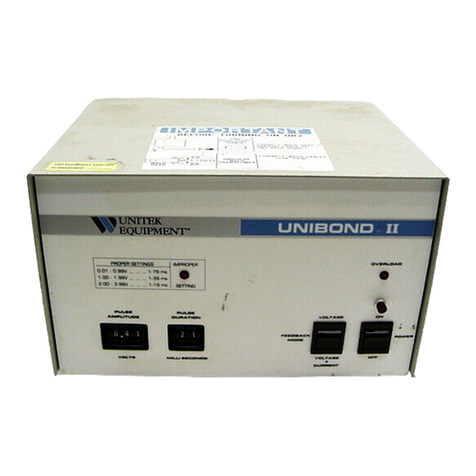
  9. Unitek UNIBOND II Manual

Unitek UNIBOND II Manual

Manual No. 990-050
Revision A: February 2001
OPERATION, MAINTENANCE AND
SERVICE MANUAL
FOR THE
UNIBOND®II
CONSTANT POWER/CONSTANT VOLTAGE
POWER SUPPLY AND METER ACCESSORY
Model UB2 Stock No. 1-191-02
Model UB2/100 Stock No. 1-191-02-01
Model UB2/230 Stock No. 1-191-02-04
Model UBM Stock No. 10-266-01
Copyright © 2001
Unitek Miyachi Corporation
All Rights Reserved
UNIBOND®II POWER SUPPLY
ii 990-050
Copyright 2001, Unitek Miyachi Corporation
The engineering designs, drawings and data contained herein are the proprietary work of
UNITEK MIYACHI CORPORATION and may not be reproduced, copied, exhibited or
otherwise used without the written authorization of UNITEK MIYACHI CORPORATION.
Printed in the United States of America
Revision Record
Revision EO Date Basis of Revision
A 17848 6/99 Re-format and correct publication.
UNIBOND®II POWER SUPPLY
990-050 iii
FOREWORD
Thank you for purchasing a Unitek Equipment®power supply.
Upon receipt of your system, please thoroughly inspect it for shipping damage prior to
installation. Should there be any damage, immediately contact the shipping company to file
a claim, and notify us at:
Unitek Equipment
1820 South Myrtle Avenue
P.O. Box 5033
Monrovia, CA 91017-7133
Phone: (626) 303-5676
FAX: (626) 358-8048
e-mail: [email protected]
The purpose of this manual is to supply operating, maintenance and service personnel with
the information needed to properly and safely operate, maintain and service Unitek
Equipment's Unibond II Power Supply and Meter Accessory.
We have made every effort to ensure that the information in this manual is accurate and
adequate.
Should questions arise, or if you have suggestions for improvement of this manual, please
contact us, as shown above.
Unitek Equipment is not responsible for any losses due to improper use of this product.
UNIBOND®II POWER SUPPLY
iv 990-050
SAFETY NOTES
This instruction manual describes how to operate, maintain and service the
Unibond II Power Supply, and provides instructions relating to it's SAFE use.
Procedures described in this manual MUST be performed as detailed by
QUALIFIED and TRAINED personnel.
For SAFETY, and to effectively take advantage of the full capabilities of the
power supply, please read this instruction manual thoroughly before
attempting to use the power supply.
Procedures other than those described in this manual or not performed as
prescribed in this manual, may expose personnel to electrical hazards.
After reading this manual, retain it for future reference when any questions
arise regarding the proper and SAFE operation of the power supply.
WARNING:
High Voltage: Lethal electrical voltage exist inside the power supply. Take
appropriate precautions when making calibration adjustments with the cover
removed.
Protective Goggles: When performing any welding operations, always wear
protective goggles.
Design Integrity: Do not modify the power supply without prior written
approval from Unitek Equipment.
Maintenance. Before performing any user maintenance or servicing the
power supply, please read Chapters 4 and 5, respectively.
Use appropriate tools, such as strippers and pressure connection tools, for
terminating and connecting cables, being careful not to nick wire conductors.
UNIBOND®II POWER SUPPLY
990-050 v
Contents
Revision Record................................................................................................................................. ii
Foreword............................................................................................................................................ iii
Safety Notes....................................................................................................................................... iv
Chapter 1: System Description...................................................................................................... 1-1
Section I: System Features ...................................................................................................... 1-1
Description............................................................................................................................. 1-1
Features............................................................................................................................ 1-1
Physical Description ........................................................................................................ 1-1
Optional Meter Assembly................................................................................................ 1-2
Section II: Specifications and Functional Description ............................................................. 1-3
Feedback Modes .................................................................................................................... 1-3
Output .................................................................................................................................... 1-3
Rise Time ............................................................................................................................... 1-3
Maximum Output Current...................................................................................................... 1-3
Maximum Secondary Loop Resistance ................................................................................. 1-3
Repetition Rate ...................................................................................................................... 1-4
Line/Load Regulation ............................................................................................................ 1-4
Accuracy ................................................................................................................................ 1-4
Voltage Feedback Mode ........................................................................................................ 1-4
Voltage + Current Feedback Mode........................................................................................ 1-4
How it Works................................................................................................................... 1-5
Weld Resistance Compensation............................................................................................. 1-7
Weld Fire Lockout Feature .................................................................................................... 1-7
Overload Protection Feature .................................................................................................. 1-7
Section III: Controls and Indicators........................................................................................... 1-8
Meter Accuracy...................................................................................................................... 1-10
Section IV: General Considerations........................................................................................... 1-11
Output Circuit ........................................................................................................................ 1-12
How the Feedback Loop Determines Output Impedance...................................................... 1-13
Chapter 2: Getting Started ............................................................................................................ 2-1
Unpacking.............................................................................................................................. 2-1
Connections and Set-up ......................................................................................................... 2-1
Connecting the Unibond II for Proper Line Voltage ....................................................... 2-1
Connect the Output Transformer ..................................................................................... 2-1
UNIBOND®II POWER SUPPLY
vi 990-050
Install Weld Head and Optics .......................................................................................... 2-1
Connect Remote Sensing Cable and Firing Cable........................................................... 2-1
Connect Power Cables ..................................................................................................... 2-2
Chapter 3: Operating Instructions................................................................................................ 3-1
Section I: Operating Precautions............................................................................................. 3-1
Section II: Preparing for Operation .......................................................................................... 3-1
Section III: Operating Functions................................................................................................ 3-1
Parallel Gap Welding............................................................................................................. 3-1
Variables for Parallel Gap Welding....................................................................................... 3-1
Gap................................................................................................................................... 3-1
Force ................................................................................................................................ 3-1
Area of Electrode Face .................................................................................................... 3-1
Pulse Duration.................................................................................................................. 3-1
Electrode Materials .......................................................................................................... 3-2
Finding the Correct Parameters ............................................................................................. 3-2
Printed Circuit Board Trace Repair – Considerations ........................................................... 3-8
Melting the Laminate....................................................................................................... 3-9
Printed Circuit Board Trace Repair ....................................................................................... 3-9
Chapter 4: User Maintenance........................................................................................................ 4-1
Section I: Maintenance Precautions ........................................................................................ 4-1
Section II: Maintenance Procedures ......................................................................................... 4-1
Electrode Maintenance .......................................................................................................... 4-1
Chapter 5: Service Procedures ...................................................................................................... 5-1
Section I: Service Precautions................................................................................................. 5-1
Section II: Calibration Procedures............................................................................................ 5-1
Calibration ............................................................................................................................. 5-1
Setup ................................................................................................................................ 5-1
Adjusting Pulse Width ..................................................................................................... 5-3
Improper Setting Indicator............................................................................................... 5-3
Check High Voltage Supply ............................................................................................ 5-3
Check Output Stage Bias ................................................................................................. 5-3
Check Output Pulse ......................................................................................................... 5-4
Check the Overload Indicator .......................................................................................... 5-4
Calibrating the Model UBM Meter Accessory................................................................ 5-4
Checking Resistance of the Weld Head........................................................................... 5-5
Section III: Troubleshooting ...................................................................................................... 5-6
Troubleshooting ..................................................................................................................... 5-6
UNIBOND®II POWER SUPPLY
990-050 vii
Section IV: How to Reach Us .................................................................................................... 5-6
Technical Assistance.............................................................................................................. 5-6
Appendix A: Technical Specifications .......................................................................................... A-1
Specifications......................................................................................................................... A-1
Index.................................................................................................................................................. Index-1

This manual suits for next models

4

Other Unitek Power Supply manuals

Unitek UNIBOND 2 User manual

Unitek

Unitek UNIBOND 2 User manual

Unitek HF2/230 User manual

Unitek

Unitek HF2/230 User manual

Popular Power Supply manuals by other brands

BE QUIET! BQT P6-470W user manual

BE QUIET!

BE QUIET! BQT P6-470W user manual

Chamberlain GPS1000 manual

Chamberlain

Chamberlain GPS1000 manual

Siemens SITOP PSU8600 manual

Siemens

Siemens SITOP PSU8600 manual

PS Audio AV-3000 Owner's reference

PS Audio

PS Audio AV-3000 Owner's reference

Pinnacle UPS Installation

Pinnacle

Pinnacle UPS Installation

Wheelock RPS-2440-A installation instructions

Wheelock

Wheelock RPS-2440-A installation instructions

CCS HLV Series manual

CCS

CCS HLV Series manual

Electro-Automatik EL 9000 T operating manual

Electro-Automatik

Electro-Automatik EL 9000 T operating manual

Pulsar HPSDC Series user manual

Pulsar

Pulsar HPSDC Series user manual

Delta Elektronika SM15-200D product manual

Delta Elektronika

Delta Elektronika SM15-200D product manual

Altronix Maximal11E installation guide

Altronix

Altronix Maximal11E installation guide

Monacor PSS-5000 quick start guide

Monacor

Monacor PSS-5000 quick start guide

Liebert Ship-Ahead Input/Output Cabinet NXL installation manual

Liebert

Liebert Ship-Ahead Input/Output Cabinet NXL installation manual

HP E3610A operating manual

HP

HP E3610A operating manual

Akyga AK-TB-13 user manual

Akyga

Akyga AK-TB-13 user manual

TDK-Lambda RWS 1500B Series instruction manual

TDK-Lambda

TDK-Lambda RWS 1500B Series instruction manual

Heath Heathkit IP-32 Schematic diagram

Heath

Heath Heathkit IP-32 Schematic diagram

Pulsar EN54-3A28LCD manual

Pulsar

Pulsar EN54-3A28LCD manual

manuals.online logo
manuals.online logoBrands
  • About & Mission
  • Contact us
  • Privacy Policy
  • Terms and Conditions

Copyright 2025 Manuals.Online. All Rights Reserved.