EPS Stromversorgung PS 9040-40 2U User manual

EPS
Stromversorgung
Doc ID: PS92UEN
Revision: 07
Date: 05/2016
Operating Guide
PS 9000 2U
DC Laboratory Power Supply
Attention! This document is only
valid for devices with rmware
“KE: 2.07” (standard models)
rep. “KE: 2.03” (GPIB models)
and “HMI: 2.06” or higher. For
availability of updates for your
device check our website or
contact us.


Page 3
EPS Stromversorgung GmbH
Alter Postweg 101 • 86159 Augsburg
Germany
Fon: +49 821 / 570451-0
Fax: +49 821 / 570451-25
www.eps-germany.de
info@eps-germany.de
PS 9000 2U Series
TABLE OF CONTENTS
1GENERAL
1.1 About this document......................................5
1.1.1 Retention and use..........................................5
1.1.2 Copyright........................................................5
1.1.3 Validity ............................................................5
1.1.4 Explanation of symbols..................................5
1.2 Warranty.........................................................5
1.3 Limitation of liability ........................................5
1.4 Disposal of equipment ...................................6
1.5 Product key ....................................................6
1.6 Intended usage ..............................................6
1.7 Safety .............................................................7
1.7.1 Safety notices.................................................7
1.7.2 Responsibility of the user...............................7
1.7.3 Responsibility of the operator .......................8
1.7.4 User requirements .........................................8
1.7.5 Alarm signals..................................................9
1.8 Technical data ................................................9
1.8.1 Approved operating conditions......................9
1.8.2 General technical data...................................9
1.8.3 Specic technical data .................................10
1.8.4 Views............................................................22
1.9 Construction and function............................26
1.9.1 General description......................................26
1.9.2 Block diagram ..............................................26
1.9.3 Scope of delivery .........................................27
1.9.4 Accessories..................................................27
1.9.5 Options .........................................................27
1.9.6 The control panel (HMI)...............................28
1.9.7 USB port.......................................................30
1.9.8 Ethernet port ................................................30
1.9.9 Analog interface ...........................................30
1.9.10 Share Bus-Connection ................................31
1.9.11 Sense connector (remote sensing) .............31
1.9.12 GPIB port (optional) .....................................31
2INSTALLATION & COMMISSIONING
2.1 Transport and storage .................................32
2.1.1 Transport ......................................................32
2.1.2 Packaging ....................................................32
2.1.3 Storage.........................................................32
2.2 Unpacking and visual check........................32
2.3 Installation ....................................................32
2.3.1 Safety procedures before installation and
use................................................................32
2.3.2 Preparation...................................................33
2.3.3 Installing the device .....................................33
2.3.4 Connection to AC supply .............................34
2.3.5 Connection to DC loads...............................34
2.3.6 Grounding of the DC output ........................35
2.3.7 Connection of remote sensing ....................36
2.3.8 Connecting the “Share” bus ........................36
2.3.9 Connecting the analog interface .................36
2.3.10 Connecting the USB port.............................37
2.3.11 Initial commission.........................................37
2.3.12 Initial network setup .....................................37
2.3.13 Commission after a rmware update or a
long period of non-use.................................38
3OPERATION AND APPLICATION
3.1 Important notes ............................................39
3.1.1 Personal safety ............................................39
3.1.2 General.........................................................39
3.2 Operating modes .........................................39
3.2.1 Voltage regulation / Constant voltage .........39
3.2.2 Current regulation / constant current / current
limiting ..........................................................39
3.2.3 Power regulation / constant power / power
limiting ..........................................................40
3.3 Alarm conditions ..........................................41
3.3.1 Power Fail ...................................................41
3.3.2 Overtemperature..........................................41
3.3.3 Overvoltage..................................................41
3.3.4 Overcurrent ..................................................41
3.3.5 Overpower....................................................41
3.4 Manual operation .........................................42
3.4.1 Switching on the device...............................42
3.4.2 Switching off the device...............................42
3.4.3 Conguration in the setup menu .................42
3.4.4 Adjustment limits..........................................46
3.4.5 Display modes for actual and set values ....47
3.4.6 Manual adjustment of set values.................47
3.4.7 The quick menu ...........................................48
3.4.8 Switching the DC output on or off................48
3.5 Remote control.............................................49
3.5.1 General.........................................................49
3.5.2 Control locations ..........................................49
3.5.3 Remote control via a digital interface ..........49
3.5.4 Remote control via the analog interface
(AI)................................................................50
3.6 Alarms and monitoring.................................54
3.6.1 Denition of terms ........................................54
3.6.2 Device alarm handling .................................54
3.7 Control panel (HMI) lock..............................55
3.8 Loading and saving a user prole ...............56
3.9 Other applications........................................57
3.9.1 Parallel operation in Share Bus mode ........57
3.9.2 Series connection ........................................58
3.9.3 Operation as battery charger.......................58
3.9.4 Two quadrants operation (2QO)..................59

Page 4
EPS Stromversorgung GmbH
Alter Postweg 101 • 86159 Augsburg
Germany
PS 9000 2U Series
Fon: +49 821 / 570451-0
Fax: +49 821 / 570451-25
www.eps-germany.de
info@eps-germany.de
4SERVICE AND MAINTENANCE
4.1 Maintenance / cleaning................................61
4.2 Fault nding / diagnosis / repair...................61
4.2.1 Replacing a defect mains fuse ....................61
4.2.2 Firmware update..........................................61
4.3 Calibration (readjustment) ...........................62
4.3.1 Preface .........................................................62
4.3.2 Preparation...................................................62
4.3.3 Calibration procedure ..................................62
5ACCESSORIES AND OPTIONS
5.1 Overview ......................................................64
6SERVICE & SUPPORT
6.1 General.........................................................64
6.2 Contact options ............................................64

Page 5
EPS Stromversorgung GmbH
Alter Postweg 101 • 86159 Augsburg
Germany
Fon: +49 821 / 570451-0
Fax: +49 821 / 570451-25
www.eps-germany.de
info@eps-germany.de
PS 9000 2U Series
1. General
1.1 About this document
1.1.1 Retention and use
This document is to be kept in the vicinity of the equipment for future reference and explanation of the operation of
the device. This document is to be delivered and kept with the equipment in case of change of location and/or user.
1.1.2 Copyright
Reprinting, copying, also partially, usage for other purposes as foreseen of this manual are forbidden and breach
may lead to legal process.
1.1.3 Validity
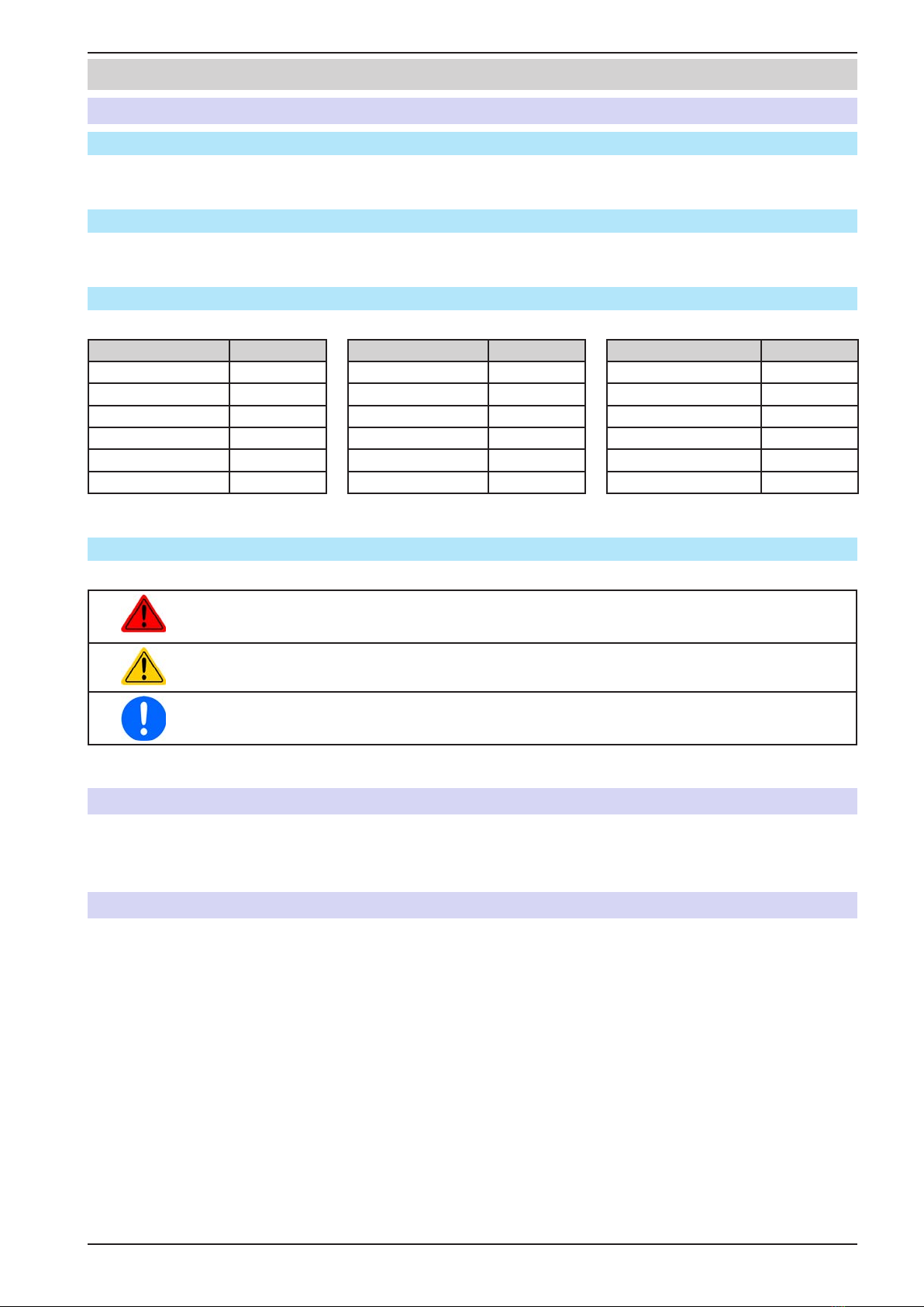
This manual is valid for the following equipment including derived variants.
Model Article nr.. Model Article nr.. Model Article nr..
PS 9040-40 2U 06230219 PS 9040-60 2U 06230220 PS 9040-120 2U 06230221
PS 9080-40 2U 06230204 PS 9080-60 2U 06230209 PS 9080-120 2U 06230214
PS 9200-15 2U 06230205 PS 9200-25 2U 06230210 PS 9200-50 2U 06230215
PS 9360-10 2U 06230206 PS 9360-15 2U 06230211 PS 9360-30 2U 06230216
PS 9500-06 2U 06230207 PS 9500-10 2U 06230212 PS 9500-20 2U 06230217
PS 9750-04 2U 06230208 PS 9750-06 2U 06230213 PS 9750-12 2U 06230218
Changes and modications for special models will be listed in a separate document.
1.1.4 Explanation of symbols
Warning and safety notices as well as general notices in this document are shown in a box with a symbol as follows:
Symbol for a life threatening danger
Symbol for general safety notices (instructions and damage protection bans) or important infor-
mation for operation
Symbol for general notices
1.2 Warranty
EPS Stromversorgung guarantees the functional competence of the applied technology and the stated performance
parameters. The warranty period begins with the delivery of free from defects equipment.
Terms of guarantee are included in the general terms and conditions (TOS) of EPS Stromversorgung.
1.3 Limitation of liability
All statements and instructions in this manual are based on current norms and regulations, up-to-date technology
and our long term knowledge and experience. The manufacturer accepts no liability for losses due to:
• Usage for purposes other than designed
• Use by untrained personnel
• Rebuilding by the customer
• Technical changes
• Use of not authorized spare parts
The actual delivered device(s) may differ from the explanations and diagrams given here due to latest technical
changes or due to customized models with the inclusion of additionally ordered options.

Page 6
EPS Stromversorgung GmbH
Alter Postweg 101 • 86159 Augsburg
Germany
PS 9000 2U Series
Fon: +49 821 / 570451-0
Fax: +49 821 / 570451-25
www.eps-germany.de
info@eps-germany.de
1.4 Disposal of equipment
A piece of equipment which is intended for disposal must, according to European laws and regulations (ElektroG,
WEEE) be returned to the manufacturer for scrapping, unless the person operating the piece of equipment or an-
other, delegated person is conducting the disposal. Our equipment falls under these regulations and is accordingly
marked with the following symbol:
1.5 Product key
Decoding of the product description on the label, using an example:
PS 9 080 - 40 3U zzz
Field for identication of installed options and/or special models
S01...S0x = Special models
HS = High Speed option installed
3W = Option 3W installed (GPIB port instead of Ethernet port)
Construction (not always given)
2U / 3U / 4U = 19" frame with 2 U, 3 U or 4 U
Maximum current of the device in Ampere
Maximum voltage of the device in Volt
Series : 8= Series 8000 or 800, 9= Series 9000
Type identication:
PS = Power Supply, usually programmable
PSI = Power Supply Intelligent, always programmable
ELR = Electronic Load with Recovery
Special models are always derived from standard models and can vary in output voltage and
current from those given.
1.6 Intended usage
The equipment is intended to be used, if a power supply or battery charger, only as a variable voltage and current
source, or, if an electronic load, only as a variable current sink.
Typical application for a power supply is DC supply to any relevant user, for a battery charger the charging of vari-
ous battery types and for electronic loads the replacement of an ohmic resistor by an adjustable DC current sink
in order to load relevant voltage and current sources of any type.
• Claims of any sort due to damage caused by non-intended usage will not be accepted.
• All damage caused by non-intended usage is solely the responsibility of the operator.

Page 7
EPS Stromversorgung GmbH
Alter Postweg 101 • 86159 Augsburg
Germany
Fon: +49 821 / 570451-0
Fax: +49 821 / 570451-25
www.eps-germany.de
info@eps-germany.de
PS 9000 2U Series
1.7 Safety
1.7.1 Safety notices
Mortal danger - Hazardous voltage
• Electrical equipment operation means that some parts can be under dangerous voltage.
Therefore all parts under voltage must be covered! This basically applies to all models,
though 40 V models according to SELV can not generate hazardous DC voltage!
• All work on connections must be carried out under zero voltage (output not connected
to load) and may only be performed by qualied and informed persons. Improper ac-
tions can cause fatal injury as well as serious material damage!
• Never touch cables or connectors directly after unplugging from mains supply as the
danger of electric shock remains!
• Never touch the contacts on DC output terminal directly after switching off the DC
output, because there still can dangerous voltage present, sinking more or less slowly
depending on the load! There also can be dangerous potential between negative DC
output to PE or positive DC output to PE due to charged X capacitors.
• The equipment must only be used as intended
• The equipment is only approved for use within the connection limits stated on the product label.
• Do not insert any object, particularly metallic, through the ventilator slots
• Avoid any use of liquids near the equipment. Protect the device from wet, damp and conden-
sation.
• For power supplies and battery chargers: do not connect users, particularly low resistance, to
devices under power; sparking may occur which can cause burns as well as damage to the
equipment and to the user.
• For electronic loads: do not connect power sources to equipment under power, sparking may
occur which can cause burns as well as damage to the equipment and to the source.
• ESD regulations must be applied when plugging interface cards or modules into the relative slot
• Interface cards or modules may only be attached or removed after the device is switched off.
It is not necessary to open the device.
• Do not connect external power sources with reversed polarity to DC input or outputs! The
equipment will be damaged.
• For power supply devices: avoid where possible connecting external power sources to the
DC output, and never those that can generate a higher voltage than the nominal voltage of
the device.
• For electronic loads: do not connect a power source to the DC input which can generate a volt-
age more than 120% of the nominal input voltage of the load. The equipment is not protected
against over voltage and may be irreparably damaged.
• Never insert a network cable which is connected to Ethernet or its components into the master-
slave socket on the back side of the device!
• Always congure the various protecting features against overvoltage overpower etc. for sensi-
tive loads to what the currently used application requires
1.7.2 Responsibility of the user
The equipment is in industrial operation. Therefore the operators are governed by the legal safety regulations.
Alongside the warning and safety notices in this manual the relevant safety, accident prevention and environmental
regulations must also be applied. In particular the users of the equipment:
• must be informed of the relevant job safety requirements
• must work to the dened responsibilities for operation, maintenance and cleaning of the equipment
• before starting work must have read and understood the operating manual
• must use the designated and recommended safety equipment.
Furthermore, anyone working with the equipment is responsible for ensuring that the device is at all times techni-
cally t for use.

Page 8
EPS Stromversorgung GmbH
Alter Postweg 101 • 86159 Augsburg
Germany
PS 9000 2U Series
Fon: +49 821 / 570451-0
Fax: +49 821 / 570451-25
www.eps-germany.de
info@eps-germany.de
1.7.3 Responsibility of the operator
Operator is any natural or legal person who uses the equipment or delegates the usage to a third party, and is
responsible during its usage for the safety of the user, other personnel or third parties.
The equipment is in industrial operation. Therefore the operators are governed by the legal safety regulations.
Alongside the warning and safety notices in this manual the relevant safety, accident prevention and environmental
regulations must also be applied. In particular the operator has to
• be acquainted with the relevant job safety requirements
• identify other possible dangers arising from the specic usage conditions at the work station via a risk assessment
• introduce the necessary steps in the operating procedures for the local conditions
• regularly control that the operating procedures are current
• update the operating procedures where necessary to reect changes in regulation, standards or operating con-
ditions.
• dene clearly and unambiguously the responsibilities for operation, maintenance and cleaning of the equipment.
• ensure that all employees who use the equipment have read and understood the manual. Furthermore the users
are to be regularly schooled in working with the equipment and the possible dangers.
• provide all personnel who work with the equipment with the designated and recommended safety equipment
Furthermore, the operator is responsible for ensuring that the device is at all times technically t for use.
1.7.4 User requirements
Any activity with equipment of this type may only be performed by persons who are able to work correctly and
reliably and satisfy the requirements of the job.
• Persons whose reaction capability is negatively inuenced by e.g. drugs, alcohol or medication may not operate
the equipment.
• Age or job related regulations valid at the operating site must always be applied.
Danger for unqualied users
Improper operation can cause person or object damage. Only persons who have the necessary
training, knowledge and experience may use the equipment.
Delegated persons are those who have been properly and demonstrably instructed in their tasks and the atten-
dant dangers.
Qualied persons are those who are able through training, knowledge and experience as well as knowledge of
the specic details to carry out all the required tasks, identify dangers and avoid personal and other risks.

Page 9
EPS Stromversorgung GmbH
Alter Postweg 101 • 86159 Augsburg
Germany
Fon: +49 821 / 570451-0
Fax: +49 821 / 570451-25
www.eps-germany.de
info@eps-germany.de
PS 9000 2U Series
1.7.5 Alarm signals
The equipment offers various possibilities for signalling alarm conditions, however, not for danger situations. The
signals may be optical (on the display as text), acoustic (piezo buzzer) or electronic (pin/status output of an analog
interface). All alarms will cause the device to permanently or temporarily switch off the DC output.
The meaning of the signals is as follows:
Signal OT
(OverTemperature)
• Overheating of the device
• DC output will be switched off temporarily
• Non-critical
Signal OVP
(OverVoltage)
• Overvoltage shutdown of the DC output due to high voltage entering the device or gener-
ated by the device itself due to a defect
• Critical! The device and/or the load could be damaged
Signal OCP
(OverCurrent)
• Shutdown of the DC output due to excess of the preset limit
• Non-critical, protects the load from excessive current consumption
Signal OPP
(OverPower)
• Shutdown of the DC output due to excess of the preset limit
• Non-critical, protects the load from excessive power consumption
Signal PF
(Power Fail)
• DC output shutdown due to AC undervoltage or defect of the AC input circuit
• Critical on overvoltage! AC input circuit could be damaged
1.8 Technical data
1.8.1 Approved operating conditions
• Use only inside dry buildings
• Ambient temperature 0-50 °C
• Operational altitude: max. 2000 m above sea level
• Max 80% relative humidity, not condensing
1.8.2 General technical data
Display: Dot matrix, 240pt x 64pt
Controls: 2 rotary knobs with button function, 5 pushbuttons
The nominal values for the device determine the maximum adjustable ranges.

Page 10
EPS Stromversorgung GmbH
Alter Postweg 101 • 86159 Augsburg
Germany
PS 9000 2U Series
Fon: +49 821 / 570451-0
Fax: +49 821 / 570451-25
www.eps-germany.de
info@eps-germany.de
1.8.3 Specic technical data
1000 W
Model 2U
PS 9040-40 PS 9080-40 PS 9200-15
AC Input
Input voltage & frequency 90...264 V AC, 50/60 Hz
Input connection 1ph (L ,N, PE)
Input fuse (internal) T16 A
Leak current < 3.5 mA
Power factor ~ 0.99
DC Output
Max. output voltage UMax 40 V 80 V 200 V
Max. output current IMax 40 A 40 A 15 A
Max. output power PMax 1000 W 1000 W 1000 W
Overvoltage protection range 0...44 V 0...88 V 0...220 V
Overcurrent protection range 0...44 A 0...44 A 0...16.5 A
Overpower protection range 0…1100 W 0…1100 W 0…1100 W
Temperature coefcient for set values Δ/K Voltage / current: 100 ppm
Output capacitance (standard version) ~5440 μF ~5440 μF ~800 μF
Output capacitance (high speed version) ~86 μF ~86 μF ~40 μF
Voltage regulation
Adjustment range 0...40 V 0...80 V 0...200 V
Accuracy (1 (at 23 ± 5 °C) < 0.1% UNom < 0.1% UNom < 0.1% UNom
Line regulation at ±10% ΔUAC < 0.02% UNom < 0.02% UNom < 0.02% UNom
Load regulation at 0...100% load < 0.05% UNom < 0.05% UNom < 0.05% UNom
Rise time 10...90% ΔU Max. 30 ms Max. 30 ms Max. 30 ms
Display: Resolution See section „1.9.6.4. Resolution of the displayed values“
Display: Accuracy (4 ≤ 0.2% UNom ≤ 0.2% UNom ≤ 0.2% UNom
Ripple (2 < 114 mVPP
< 8 mVRMS
< 114 mVPP
< 8 mVRMS
< 164 mVPP
< 34 mVRMS
Remote sensing compensation Max. 5% UNom Max. 5% UNom Max. 5% UNom
Output voltage fall time (at no load)after
switching DC output off - - Down from 100% to
<60 V: less than 10 s
Current regulation
Adjustment range 0...40 A 0...40 A 0...15 A
Accuracy (1 (at 23 ± 5 °C) < 0.2% INom < 0.2% INom < 0.2% INom
Line regulation at ±10% ΔUAC < 0.05% INom < 0.05% INom < 0.05% INom
Load regulation at 0...100% ΔUOUT < 0.15% INom < 0.15% INom < 0.15% INom
Ripple (2 < 3.7 mARMS < 3.7 mARMS < 2.2 mARMS
Display: Resolution See section „1.9.6.4. Resolution of the displayed values“
Display: Accuracy (4 ≤ 0.2% INom ≤ 0.2% INom ≤ 0.2% INom
Transient time after load step < 1.5 ms < 1.5 ms < 1.5 ms
Power regulation
Adjustment range 0…1000 W 0…1000 W 0…1000 W
Accuracy (1 (at 23 ± 5 °C) < 1% PNom < 1% PNom < 1% PNom
Line regulation at ±10% ΔUAC < 0.05% PNom < 0.05% PNom < 0.05% PNom
Load regulation at 10-90% ΔUOUT * ΔIOUT < 0.75% PNom < 0.75% PNom < 0.75% PNom
Display: Resolution See section „1.9.6.4. Resolution of the displayed values“
Display: Accuracy (4 ≤ 0.8% PNom ≤ 0.8% PNom ≤ 0.8% PNom
Efciency (3 ~ 92% ~ 92% ~ 93%
(1 Related to the nominal values, the accuracy denes the maximum deviation between an adjusted values and the true (actual) value.
Example: a 80 V model has min. 0.1% voltage accuracy, that is 80 mV. When adjusting the voltage to 5 V, the actual value is allowed to differ max. 80 mV, which
means it might be between 4.92 V and 5.08 V.
(2 RMS value: LF 0...300 kHz, PP value: HF 0...20 MHz
(3 Typical value at 100% output voltage and 100% power
(4 The display error adds to the error of the related actual value on the DC output.

Page 11
EPS Stromversorgung GmbH
Alter Postweg 101 • 86159 Augsburg
Germany
Fon: +49 821 / 570451-0
Fax: +49 821 / 570451-25
www.eps-germany.de
info@eps-germany.de
PS 9000 2U Series
1000 W
Model 2U
PS 9040-40 PS 9080-40 PS 9200-15
Analog interface (1
Set value inputs U, I, P U, I, P U, I, P
Actual value output U, I U, I U, I
Control signals DC on/off,
Remote on/off
DC on/off,
Remote on/off
DC on/off,
Remote on/off
Status signals CV, OVP, OT CV, OVP, OT CV, OVP, OT
Galvanic isolation to the device Max. 1500 V DC Max. 1500 V DC Max. 1500 V DC
Sample rate of inputs & outputs 500 Hz
Insulation Allowed oat (potential shift) on the DC output:
Negative terminal to PE Max. ±400 V DC ±400 V DC ±400 V DC
Positive terminal to PE Max. +440 V DC +480 V DC +600 V DC
Miscellaneous
Cooling Temperature controlled fans, front inlet, rear exhaust
Ambient temperature 0..50 °C
Storage temperature -20...70 °C
Humidity < 80%, not condensing
Standards EN 61010, EN 61326
Overvoltage category 2
Protection class 1
Pollution degree 2
Operational altitude < 2000 m
Digital interfaces
Featured 1x USB-B, 1x Ethernet (2, 1x GPIB (optional with option 3W)
Galvanic isolation from device Max. 1500 V DC
USB specication USB 2.0, socket type B, VCOM driver
USB response time SCPI: max. 5 ms, ModBus: max. 5 ms
Ethernet specication (2 RJ45, 10/100 Mbit, TCP/IP, ICMP, HTTP, DHCP
Ethernet response time SCPI: max. 7 ms, ModBus: 9-17 ms
GPIB specication (optional) 24 pin Centronics socket acc. IEEE-488, for standard GPIB cables
GPIB response time max. 5 ms
Terminals
Rear side Share Bus, DC output, AC input, remote sensing, analog interface, USB-B, Ethernet
Dimensions
Enclosure (WxHxD) 19“ x 2U x 463 mm
Total (WxHxD) 483 x 88 x min. 535 mm (depending on DC out terminal type)
Weight ~ 12 kg ~ 12 kg ~ 12 kg
Article number of std. model (3 06230219 06230204 06230205
Article number of HS model (3 06730219 06730204 06730205
(1 For technical specications of the analog interface see „3.5.4.4 Analog interface specication“ on page 51
(2 Only in the standard version
(3 Article number of the base version, devices with further options will have a different number

Page 12
EPS Stromversorgung GmbH
Alter Postweg 101 • 86159 Augsburg
Germany
PS 9000 2U Series
Fon: +49 821 / 570451-0
Fax: +49 821 / 570451-25
www.eps-germany.de
info@eps-germany.de
1000 W
Model 2U
PS 9360-10 PS 9500-06 PS 9750-04
AC Input
Input voltage & frequency 90...264 V AC, 50/60 Hz
Input connection 1ph (L ,N, PE)
Input fuse (internal) T16 A
Leak current < 3.5 mA
Power factor ~ 0.99
DC Output
Max. output voltage UMax 360 V 500 V 750 V
Max. output current IMax 10 A 6 A 4 A
Max. output power PMax 1000 W 1000 W 1000 W
Overvoltage protection range 0...396 V 0...550 V 0...825 V
Overcurrent protection range 0...11 A 0...6.6 A 0...4.4 A
Overpower protection range 0…1100 W 0…1100 W 0…1100 W
Temperature coefcient for set values Δ/K Voltage / current: 100 ppm
Output capacitance (standard version) ~330 μF ~120 μF ~35 μF
Output capacitance (high speed version) ~20 μF ~15 μF ~9 μF
Voltage regulation
Adjustment range 0...360 V 0...500 V 0...750 V
Accuracy (1 (at 23 ± 5 °C) < 0.1% UNom < 0.1% UNom < 0.1% UNom
Line regulation at ±10% ΔUAC < 0.02% UNom < 0.02% UNom < 0.02% UNom
Load regulation at 0...100% load < 0.05% UNom < 0.05% UNom < 0.05% UNom
Rise time 10...90% ΔU Max. 30 ms Max. 30 ms Max. 30 ms
Display: Resolution See section „1.9.6.4. Resolution of the displayed values“
Display: Accuracy (4 ≤ 0.2% UNom ≤ 0.2% UNom ≤ 0.2% UNom
Ripple (2 < 210 mVPP
< 59 mVRMS
< 190 mVPP
< 48 mVRMS
< 212 mVPP
< 60 mVRMS
Remote sensing compensation Max. 5% UNom Max. 5% UNom Max. 5% UNom
Output voltage fall time (at no load)after
switching DC output off Down from 100% to <60 V: less than 10 s
Current regulation
Adjustment range 0...10 A 0...6 A 0...4 A
Accuracy (1 (at 23 ± 5 °C) < 0.2% INom < 0.2% INom < 0.2% INom
Line regulation at ±10% ΔUAC < 0.05% INom < 0.05% INom < 0.05% INom
Load regulation at 0...100% ΔUOUT < 0.15% INom < 0.15% INom < 0.15% INom
Ripple (2 < 1.6 mARMS < 0.5 mARMS < 0.3 mARMS
Display: Resolution See section „1.9.6.4. Resolution of the displayed values“
Display: Accuracy (4 ≤ 0.2% INom ≤ 0.2% INom ≤ 0.2% INom
Transient time after load step < 1.5 ms < 1.5 ms < 1.5 ms
Power regulation
Adjustment range 0…1000 W 0…1000 W 0…1000 W
Accuracy (1 (at 23 ± 5 °C) < 1% PNom < 1% PNom < 1% PNom
Line regulation at ±10% ΔUAC < 0.05% PNom < 0.05% PNom < 0.05% PNom
Load regulation at 10-90% ΔUOUT * ΔIOUT < 0.75% PNom < 0.75% PNom < 0.75% PNom
Display: Resolution See section „1.9.6.4. Resolution of the displayed values“
Display: Accuracy (4 ≤ 0.8% PNom ≤ 0.8% PNom ≤ 0.8% PNom
Efciency (3 ~ 93% ~ 93% ~ 93%
(1 Related to the nominal values, the accuracy denes the maximum deviation between an adjusted values and the true (actual) value.
Example: a 80 V model has min. 0.1% voltage accuracy, that is 80 mV. When adjusting the voltage to 5 V, the actual value is allowed to differ max. 80 mV, which
means it might be between 4.92 V and 5.08 V.
(2 RMS value: LF 0...300 kHz, PP value: HF 0...20 MHz
(3 Typical value at 100% output voltage and 100% power
(4 The display error adds to the error of the related actual value on the DC output.

Page 13
EPS Stromversorgung GmbH
Alter Postweg 101 • 86159 Augsburg
Germany
Fon: +49 821 / 570451-0
Fax: +49 821 / 570451-25
www.eps-germany.de
info@eps-germany.de
PS 9000 2U Series
1000 W
Model 2U
PS 9360-10 PS 9500-06 PS 9750-04
Analog interface (1
Set value inputs U, I, P U, I, P U, I, P
Actual value output U, I U, I U, I
Control signals DC on/off,
Remote on/off
DC on/off,
Remote on/off
DC on/off,
Remote on/off
Status signals CV, OVP, OT CV, OVP, OT CV, OVP, OT
Galvanic isolation to the device Max. 1500 V DC Max. 1500 V DC Max. 1500 V DC
Sample rate of inputs & outputs 500 Hz
Insulation Allowed oat (potential shift) on the DC output:
Negative terminal to PE Max. ±400 V DC ±400 V DC ±400 V DC
Positive terminal to PE Max. +760 V DC +900 V DC +1150 V DC
Miscellaneous
Cooling Temperature controlled fans, front inlet, rear exhaust
Ambient temperature 0..50 °C
Storage temperature -20...70 °C
Humidity < 80%, not condensing
Standards EN 61010, EN 61326
Overvoltage category 2
Protection class 1
Pollution degree 2
Operational altitude < 2000 m
Digital interfaces
Featured 1x USB-B, 1x Ethernet (2, 1x GPIB (optional with option 3W)
Galvanic isolation from device Max. 1500 V DC
USB specication USB 2.0, socket type B, VCOM driver
USB response time SCPI: max. 5 ms, ModBus: max. 5 ms
Ethernet specication (2 RJ45, 10/100 Mbit, TCP/IP, ICMP, HTTP, DHCP
Ethernet response time SCPI: max. 7 ms, ModBus: 9-17 ms
GPIB specication (optional) 24 pin Centronics socket acc. IEEE-488, for standard GPIB cables
GPIB response time max. 5 ms
Terminals
Rear side Share Bus, DC output, AC input, remote sensing, analog interface, USB-B, Ethernet
Dimensions
Enclosure (WxHxD) 19“ x 2U x 463 mm
Total (WxHxD) 483 x 88 x min. 535 mm (depending on DC out terminal type)
Weight ~ 12 kg ~ 12 kg ~ 12 kg
Article number of std. model (3 06230206 06230207 06230208
Article number of HS model (3 06730206 06730207 06730208
(1 For technical specications of the analog interface see „3.5.4.4 Analog interface specication“ on page 51
(2 Only in the standard version
(3 Article number of the base version, devices with further options will have a different number

Page 14
EPS Stromversorgung GmbH
Alter Postweg 101 • 86159 Augsburg
Germany
PS 9000 2U Series
Fon: +49 821 / 570451-0
Fax: +49 821 / 570451-25
www.eps-germany.de
info@eps-germany.de
1500 W
Model 2U
PS 9040-60 PS 9080-60 PS 9200-25
AC Input
Input voltage 90...264 V AC, 50/60 Hz
- with additional derating 90...150 V AC
Input connection 1ph (L ,N, PE)
Input fuse (internal) T16 A
Leak current < 3.5 mA
Power factor ~ 0.99
DC Output
Max. output voltage UMax 40 V 80 V 200 V
Max. output current IMax 60 A 60 A 25 A
Max. output power PMax 1500 W 1500 W 1500 W
Max. output power PMax with derating 1000 W 1000 W 1000 W
Overvoltage protection range 0...44 V 0...88 V 0...220 V
Overcurrent protection range 0...66 A 0...66 A 0...27.5 A
Overpower protection range 0…1650 W 0…1650 W 0…1650 W
Temperature coefcient for set values Δ/K Voltage / current: 100 ppm
Output capacitance (standard version) ~5440 μF ~5440 μF ~800 μF
Output capacitance (high speed version) ~86 μF ~86 μF ~40 μF
Voltage regulation
Adjustment range 0..40 V 0...80 V 0...200 V
Accuracy (1 (at 23 ± 5 °C) < 0.1% UNom < 0.1% UNom < 0.1% UNom
Line regulation at ±10% ΔUAC < 0.02% UNom < 0.02% UNom < 0.02% UNom
Load regulation at 0...100% load < 0.05% UNom < 0.05% UNom < 0.05% UNom
Rise time 10...90% ΔU Max. 30 ms Max. 30 ms Max. 30 ms
Display: Resolution See section „1.9.6.4. Resolution of the displayed values“
Display: Accuracy (4 ≤ 0.2% UNom ≤ 0.2% UNom ≤ 0.2% UNom
Ripple (2 < 114 mVPP
< 8 mVRMS
< 114 mVPP
< 8 mVRMS
< 164 mVPP
< 34 mVRMS
Remote sensing compensation Max. 5% UNom Max. 5% UNom Max. 5% UNom
Output voltage fall time (at no load)after
switching DC output off - - Down from 100% to
<60 V: less than 10 s
Current regulation
Adjustment range 0...60 A 0...60 A 0...25 A
Accuracy (1 (at 23 ± 5 °C) < 0.2% INom < 0.2% INom < 0.2% INom
Line regulation at ±10% ΔUAC < 0.05% INom < 0.05% INom < 0.05% INom
Load regulation at 0...100% ΔUOUT < 0.15% INom < 0.15% INom < 0.15% INom
Ripple (2 < 5.6 mARMS < 5.6 mARMS < 3.3 mARMS
Display: Resolution See section „1.9.6.4. Resolution of the displayed values“
Display: Accuracy (4 ≤ 0.2% INom ≤ 0.2% INom ≤ 0.2% INom
Transient time after load step < 1.5 ms < 1.5 ms < 1.5 ms
Power regulation
Adjustment range 0…1500 W 0…1500 W 0…1500 W
Accuracy (1 (at 23 ± 5 °C) < 1% PNom < 1% PNom < 1% PNom
Line regulation at ±10% ΔUAC < 0.05% PNom < 0.05% PNom < 0.05% PNom
Load regulation at 10-90% ΔUOUT * ΔIOUT < 0.75% PNom < 0.75% PNom < 0.75% PNom
Display: Resolution See section „1.9.6.4. Resolution of the displayed values“
Display: Accuracy (4 ≤ 0.8% PNom ≤ 0.8% PNom ≤ 0.7% PNom
Efciency (3 ~ 92% ~ 92% ~ 93%
(1 Related to the nominal values, the accuracy denes the maximum deviation between an adjusted values and the true (actual) value.
Example: a 80 V model has min. 0.1% voltage accuracy, that is 80 mV. When adjusting the voltage to 5 V, the actual value is allowed to differ max. 80 mV, which
means it might be between 4.92 V and 5.08 V.
(2 RMS value: LF 0...300 kHz, PP value: HF 0...20 MHz
(3 Typical value at 100% output voltage and 100% power
(4 The display error adds to the error of the related actual value on the DC output.

Page 15
EPS Stromversorgung GmbH
Alter Postweg 101 • 86159 Augsburg
Germany
Fon: +49 821 / 570451-0
Fax: +49 821 / 570451-25
www.eps-germany.de
info@eps-germany.de
PS 9000 2U Series
1500 W
Model 2U
PS 9040-60 PS 9080-60 PS 9200-25
Analog interface (1
Set value inputs U, I, P U, I, P U, I, P
Actual value output U, I U, I U, I
Control signals DC on/off,
Remote on/off
DC on/off,
Remote on/off
DC on/off,
Remote on/off
Status signals CV, OVP, OT CV, OVP, OT CV, OVP, OT
Galvanic isolation to the device Max. 1500 V DC Max. 1500 V DC Max. 1500 V DC
Sample rate of inputs & outputs 500 Hz
Insulation Allowed oat (potential shift) on the DC output:
Negative terminal to PE Max. ±400 V DC ±400 V DC ±400 V DC
Positive terminal to PE Max. +440 V DC +480 V DC +600 V DC
Miscellaneous
Cooling Temperature controlled fans, front inlet, rear exhaust
Ambient temperature 0..50 °C
Storage temperature -20...70 °C
Humidity < 80%, not condensing
Standards EN 61010, EN 61326
Overvoltage category 2
Protection class 1
Pollution degree 2
Operational altitude < 2000 m
Digital interfaces
Featured 1x USB-B, 1x Ethernet (2, 1x GPIB (optional with option 3W)
Galvanic isolation from device Max. 1500 V DC
USB specication USB 2.0, socket type B, VCOM driver
USB response time SCPI: max. 5 ms, ModBus: max. 5 ms
Ethernet specication (2 RJ45, 10/100 Mbit, TCP/IP, ICMP, HTTP, DHCP
Ethernet response time SCPI: max. 7 ms, ModBus: 9-17 ms
GPIB specication (optional) 24 pin Centronics socket acc. IEEE-488, for standard GPIB cables
GPIB response time max. 5 ms
Terminals
Rear side Share Bus, DC output, AC input, remote sensing, analog interface, USB-B, Ethernet
Dimensions
Enclosure (WxHxD) 19“ x 2U x 463 mm
Total (WxHxD) 483 x 88 x min. 535 mm (depending on DC out terminal type)
Weight ~ 12 kg ~ 12 kg ~ 12 kg
Article number of std. model (3 06230220 06230209 06230210
Article number of HS model (3 06730220 06730209 06730210
(1 For technical specications of the analog interface see „3.5.4.4 Analog interface specication“ on page 51
(2 Only in the standard version
(3 Article number of the base version, devices with further options will have a different number

Page 16
EPS Stromversorgung GmbH
Alter Postweg 101 • 86159 Augsburg
Germany
PS 9000 2U Series
Fon: +49 821 / 570451-0
Fax: +49 821 / 570451-25
www.eps-germany.de
info@eps-germany.de
1500 W
Model 2U
PS 9360-15 PS 9500-10 PS 9750-06
AC Input
Input voltage 90...264 V AC, 50/60 Hz
- with additional derating 90...150 V AC
Input connection 1ph (L ,N, PE)
Input fuse (internal) T16 A
Leak current < 3.5 mA
Power factor ~ 0.99
DC Output
Max. output voltage UMax 360 V 500 V 750 V
Max. output current IMax 15 A 10 A 6 A
Max. output power PMax 1500 W 1500 W 1500 W
Max. output power PMax with derating 1000 W 1000 W 1000 W
Overvoltage protection range 0...396 V 0...550 V 0...825 V
Overcurrent protection range 0...16.5 A 0...11 A 0...6.6 A
Overpower protection range 0…1650 W 0…1650 W 0…1650 W
Temperature coefcient for set values Δ/K Voltage / current: 100 ppm
Output capacitance (standard version) ~330 μF ~120 μF ~35 μF
Output capacitance (high speed version) ~20 μF ~15 μF ~9 μF
Voltage regulation
Adjustment range 0...360 V 0...500 V 0...750 V
Accuracy (1 (at 23 ± 5 °C) < 0.1% UNom < 0.1% UNom < 0.1% UNom
Line regulation at ±10% ΔUAC < 0.02% UNom < 0.02% UNom < 0.02% UNom
Load regulation at 0...100% load < 0.05% UNom < 0.05% UNom < 0.05% UNom
Rise time 10...90% ΔU Max. 30 ms Max. 30 ms Max. 30 ms
Display: Resolution See section „1.9.6.4. Resolution of the displayed values“
Display: Accuracy (4 ≤ 0.2% UNom ≤ 0.2% UNom ≤ 0.2% UNom
Ripple (2 < 210 mVPP
< 59 mVRMS
< 190 mVPP
< 48 mVRMS
< 212 mVPP
< 60 mVRMS
Remote sensing compensation Max. 5% UNom Max. 5% UNom Max. 5% UNom
Output voltage fall time (at no load)after
switching DC output off Down from 100% to <60 V: less than 10 s
Current regulation
Adjustment range 0...15 A 0...10 A 0...6 A
Accuracy (1 (at 23 ± 5 °C) < 0.2% INom < 0.2% INom < 0.2% INom
Line regulation at ±10% ΔUAC < 0.05% INom < 0.05% INom < 0.05% INom
Load regulation at 0...100% ΔUOUT < 0.15% INom < 0.15% INom < 0.15% INom
Ripple (2 < 2.4 mARMS < 0.7 mARMS < 0.5 mARMS
Display: Resolution See section „1.9.6.4. Resolution of the displayed values“
Display: Accuracy (4 ≤ 0.2% INom ≤ 0.2% INom ≤ 0.2% INom
Transient time after load step < 1.5 ms < 1.5 ms < 1.5 ms
Power regulation
Adjustment range 0…1500 W 0…1500 W 0…1500 W
Accuracy (1 (at 23 ± 5 °C) < 1% PNom < 1% PNom < 1% PNom
Line regulation at ±10% ΔUAC < 0.05% PNom < 0.05% PNom < 0.05% PNom
Load regulation at 10-90% ΔUOUT * ΔIOUT < 0.75% PNom < 0.75% PNom < 0.75% PNom
Display: Resolution See section „1.9.6.4. Resolution of the displayed values“
Display: Accuracy (4 ≤ 0.7% PNom ≤ 0.8% PNom ≤ 0.85% PNom
Efciency (3 ~ 93% ~ 93% ~ 93%
(1 Related to the nominal values, the accuracy denes the maximum deviation between an adjusted values and the true (actual) value.
Example: a 80 V model has min. 0.1% voltage accuracy, that is 80 mV. When adjusting the voltage to 5 V, the actual value is allowed to differ max. 80 mV, which
means it might be between 4.92 V and 5.08 V.
(2 RMS value: LF 0...300 kHz, PP value: HF 0...20 MHz
(3 Typical value at 100% output voltage and 100% power
(4 The display error adds to the error of the related actual value on the DC output.

Page 17
EPS Stromversorgung GmbH
Alter Postweg 101 • 86159 Augsburg
Germany
Fon: +49 821 / 570451-0
Fax: +49 821 / 570451-25
www.eps-germany.de
info@eps-germany.de
PS 9000 2U Series
1500 W
Model 2U
PS 9360-15 PS 9500-10 PS 9750-06
Analog interface (1
Set value inputs U, I, P U, I, P U, I, P
Actual value output U, I U, I U, I
Control signals DC on/off,
Remote on/off
DC on/off,
Remote on/off
DC on/off,
Remote on/off
Status signals CV, OVP, OT CV, OVP, OT CV, OVP, OT
Galvanic isolation to the device Max. 1500 V DC Max. 1500 V DC Max. 1500 V DC
Sample rate of inputs & outputs 500 Hz
Insulation Allowed oat (potential shift) on the DC output:
Negative terminal to PE Max. ±400 V DC ±400 V DC ±400 V DC
Positive terminal to PE Max. +760 V DC +900 V DC +1150 V DC
Miscellaneous
Cooling Temperature controlled fans, front inlet, rear exhaust
Ambient temperature 0..50 °C
Storage temperature -20...70 °C
Humidity < 80%, not condensing
Standards EN 61010, EN 61326
Overvoltage category 2
Protection class 1
Pollution degree 2
Operational altitude < 2000 m
Digital interfaces
Featured 1x USB-B, 1x Ethernet (2, 1x GPIB (optional with option 3W)
Galvanic isolation from device Max. 1500 V DC
USB specication USB 2.0, socket type B, VCOM driver
USB response time SCPI: max. 5 ms, ModBus: max. 5 ms
Ethernet specication (2 RJ45, 10/100 Mbit, TCP/IP, ICMP, HTTP, DHCP
Ethernet response time SCPI: max. 7 ms, ModBus: 9-17 ms
GPIB specication (optional) 24 pin Centronics socket acc. IEEE-488, for standard GPIB cables
GPIB response time max. 5 ms
Terminals
Rear side Share Bus, DC output, AC input, remote sensing, analog interface, USB-B, Ethernet
Dimensions
Enclosure (WxHxD) 19“ x 2U x 463 mm
Total (WxHxD) 483 x 88 x min. 535 mm (depending on DC out terminal type)
Weight ~ 12 kg ~ 12 kg ~ 12 kg
Article number of std. model (3 06230211 06230212 06230213
Article number of HS model (3 06730211 06730212 06730213
(1 For technical specications of the analog interface see „3.5.4.4 Analog interface specication“ on page 51
(2 Only in the standard version
(3 Article number of the base version, devices with further options will have a different number

Page 18
EPS Stromversorgung GmbH
Alter Postweg 101 • 86159 Augsburg
Germany
PS 9000 2U Series
Fon: +49 821 / 570451-0
Fax: +49 821 / 570451-25
www.eps-germany.de
info@eps-germany.de
3000 W
Model 2U
PS 9040-120 PS 9080-120 PS 9200-50
AC Input
Input voltage 180...264 V AC, 50/60 Hz
- with additional derating 180...207 V AC
Input connection 1ph (L ,N, PE)
Input fuse (internal) T16 A
Leak current < 3.5 mA
Power factor ~ 0.99
DC Output
Max. output voltage UMax 40 V 80 V 200 V
Max. output current IMax 120 A 120 A 50 A
Max. output power PMax 3000 W 3000 W 3000 W
Max. output power PMax with derating 2500 W 2500 W 2500 W
Overvoltage protection range 0...44 V 0...88 V 0...220 V
Overcurrent protection range 0...132 A 0...132 A 0...55 A
Overpower protection range 0…3300 W 0…3300 W 0…3300 W
Temperature coefcient for set values Δ/K Voltage / current: 100 ppm
Output capacitance (standard version) ~10880 μF ~10880 μF ~1600 μF
Output capacitance (high speed version) ~172 μF ~172 μF ~80 μF
Voltage regulation
Adjustment range 0...40 V 0...80 V 0...200 V
Accuracy (1 (at 23 ± 5 °C) < 0.1% UNom < 0.1% UNom < 0.1% UNom
Line regulation at ±10% ΔUAC < 0.02% UNom < 0.02% UNom < 0.02% UNom
Load regulation at 0...100% load < 0.05% UNom < 0.05% UNom < 0.05% UNom
Rise time 10...90% ΔU Max. 30 ms Max. 30 ms Max. 30 ms
Display: Resolution See section „1.9.6.4. Resolution of the displayed values“
Display: Accuracy (4 ≤ 0.2% UNom ≤ 0.2% UNom ≤ 0.2% UNom
Ripple (2 < 114 mVPP
< 8 mVRMS
< 114 mVPP
< 8 mVRMS
< 164 mVPP
< 34 mVRMS
Remote sensing compensation Max. 5% UNom Max. 5% UNom Max. 5% UNom
Output voltage fall time (at no load)after
switching DC output off - - Down from 100% to
<60 V: less than 10 s
Current regulation
Adjustment range 0...120 A 0...120 A 0...50 A
Accuracy (1 (at 23 ± 5 °C) < 0.2% INom < 0.2% INom < 0.2% INom
Line regulation at ±10% ΔUAC < 0.05% INom < 0.05% INom < 0.05% INom
Load regulation at 0...100% ΔUOUT < 0.15% INom < 0.15% INom < 0.15% INom
Ripple (2 < 11 mARMS < 11 mARMS < 6.5 mARMS
Display: Resolution See section „1.9.6.4. Resolution of the displayed values“
Display: Accuracy (4 ≤ 0.2% INom ≤ 0.2% INom ≤ 0.2% INom
Transient time after load step < 1.5 ms < 1.5 ms < 1.5 ms
Power regulation
Adjustment range 0…3000 W 0…3000 W 0…3000 W
Accuracy (1 (at 23 ± 5 °C) < 1% PNom < 1% PNom < 1% PNom
Line regulation at ±10% ΔUAC < 0.05% PNom < 0.05% PNom < 0.05% PNom
Load regulation at 10-90% ΔUOUT * ΔIOUT < 0.75% PNom < 0.75% PNom < 0.75% PNom
Display: Resolution See section „1.9.6.4. Resolution of the displayed values“
Display: Accuracy (4 ≤ 0.8% PNom ≤ 0.8% PNom ≤ 0.85% PNom
Efciency (3 ~ 92% ~ 92% ~ 93%
(1 Related to the nominal values, the accuracy denes the maximum deviation between an adjusted values and the true (actual) value.
Example: a 80 V model has min. 0.1% voltage accuracy, that is 80 mV. When adjusting the voltage to 5 V, the actual value is allowed to differ max. 80 mV, which
means it might be between 4.92 V and 5.08 V.
(2 RMS value: LF 0...300 kHz, PP value: HF 0...20 MHz
(3 Typical value at 100% output voltage and 100% power
(4 The display error adds to the error of the related actual value on the DC output.

Page 19
EPS Stromversorgung GmbH
Alter Postweg 101 • 86159 Augsburg
Germany
Fon: +49 821 / 570451-0
Fax: +49 821 / 570451-25
www.eps-germany.de
info@eps-germany.de
PS 9000 2U Series
3000 W
Model 2U
PS 9040-120 PS 9080-120 PS 9200-50
Analog interface (1
Set value inputs U, I, P U, I, P U, I, P
Actual value output U, I U, I U, I
Control signals DC on/off,
Remote on/off
DC on/off,
Remote on/off
DC on/off,
Remote on/off
Status signals CV, OVP, OT CV, OVP, OT CV, OVP, OT
Galvanic isolation to the device Max. 1500 V DC Max. 1500 V DC Max. 1500 V DC
Sample rate of inputs & outputs 500 Hz
Insulation Allowed oat (potential shift) on the DC output:
Negative terminal to PE Max. ±400 V DC ±400 V DC ±400 V DC
Positive terminal to PE Max. +440 V DC +480 V DC +600 V DC
Miscellaneous
Cooling Temperature controlled fans, front inlet, rear exhaust
Ambient temperature 0..50 °C
Storage temperature -20...70 °C
Humidity < 80%, not condensing
Standards EN 61010, EN 61326
Overvoltage category 2
Protection class 1
Pollution degree 2
Operational altitude < 2000 m
Digital interfaces
Featured 1x USB-B, 1x Ethernet (2, 1x GPIB (optional with option 3W)
Galvanic isolation from device Max. 1500 V DC
USB specication USB 2.0, socket type B, VCOM driver
USB response time SCPI: max. 5 ms, ModBus: max. 5 ms
Ethernet specication (2 RJ45, 10/100 Mbit, TCP/IP, ICMP, HTTP, DHCP
Ethernet response time SCPI: max. 7 ms, ModBus: 9-17 ms
GPIB specication (optional) 24 pin Centronics socket acc. IEEE-488, for standard GPIB cables
GPIB response time max. 5 ms
Terminals
Rear side Share Bus, DC output, AC input, remote sensing, analog interface, USB-B, Ethernet
Dimensions
Enclosure (WxHxD) 19“ x 2U x 463 mm
Total (WxHxD) 483 x 88 x min. 535 mm (depending on DC out terminal type)
Weight ~ 15 kg ~ 15 kg ~ 15 kg
Article number of std. model (3 06230221 06230214 06230215
Article number of HS model (3 06730221 06730214 06730215
(1 For technical specications of the analog interface see „3.5.4.4 Analog interface specication“ on page 51
(2 Only in the standard version
(3 Article number of the base version, devices with further options will have a different number

Page 20
EPS Stromversorgung GmbH
Alter Postweg 101 • 86159 Augsburg
Germany
PS 9000 2U Series
Fon: +49 821 / 570451-0
Fax: +49 821 / 570451-25
www.eps-germany.de
info@eps-germany.de
3000 W
Model 2U
PS 9360-30 PS 9500-20 PS 9750-12
AC Input
Input voltage 180...264 V AC, 50/60 Hz
- with additional derating 180...207 V AC
Input connection 1ph (L ,N, PE)
Input fuse (internal) T16 A
Leak current < 3.5 mA
Power factor ~ 0.99
DC Output
Max. output voltage UMax 360 V 500 V 750 V
Max. output current IMax 30 A 20 A 12 A
Max. output power PMax 3000 W 3000 W 3000 W
Max. output power PMax with derating 2500 W 2500 W 2500 W
Overvoltage protection range 0...396 V 0...550 V 0...825 V
Overcurrent protection range 0...33 A 0...22 A 0...13.2 A
Overpower protection range 0…3300 W 0…3300 W 0…3300 W
Temperature coefcient for set values Δ/K Voltage / current: 100 ppm
Output capacitance (standard version) ~660 μF ~240 μF ~70 μF
Output capacitance (high speed version) ~40 μF ~30 μF ~18 μF
Voltage regulation
Adjustment range 0...360 V 0...500 V 0...750 V
Accuracy (1 (at 23 ± 5 °C) < 0.1% UNom < 0.1% UNom < 0.1% UNom
Line regulation at ±10% ΔUAC < 0.02% UNom < 0.02% UNom < 0.02% UNom
Load regulation at 0...100% load < 0.05% UNom < 0.05% UNom < 0.05% UNom
Rise time 10...90% ΔU Max. 30 ms Max. 30 ms Max. 30 ms
Display: Resolution See section „1.9.6.4. Resolution of the displayed values“
Display: Accuracy (4 ≤ 0.2% UNom ≤ 0.2% UNom ≤ 0.2% UNom
Ripple (2 < 210 mVPP
< 59 mVRMS
< 190 mVPP
< 48 mVRMS
< 212 mVPP
< 60 mVRMS
Remote sensing compensation Max. 5% UNom Max. 5% UNom Max. 5% UNom
Output voltage fall time (at no load)after
switching DC output off Down from 100% to <60 V: less than 10 s
Current regulation
Adjustment range 0...30 A 0...20 A 0...12 A
Accuracy (1 (at 23 ± 5 °C) < 0.2% INom < 0.2% INom < 0.2% INom
Line regulation at ±10% ΔUAC < 0.05% INom < 0.05% INom < 0.05% INom
Load regulation at 0...100% ΔUOUT < 0.15% INom < 0.15% INom < 0.15% INom
Ripple (2 < 5 mARMS < 1.5 mARMS < 0.9 mARMS
Display: Resolution See section „1.9.6.4. Resolution of the displayed values“
Display: Accuracy (4 ≤ 0.2% INom ≤ 0.2% INom ≤ 0.2% INom
Transient time after load step < 1.5 ms < 1.5 ms < 1.5 ms
Power regulation
Adjustment range 0…3000 W 0…3000 W 0…3000 W
Accuracy (1 (at 23 ± 5 °C) < 1% PNom < 1% PNom < 1% PNom
Line regulation at ±10% ΔUAC < 0.05% PNom < 0.05% PNom < 0.05% PNom
Load regulation at 10-90% ΔUOUT * ΔIOUT < 0.75% PNom < 0.75% PNom < 0.75% PNom
Display: Resolution See section „1.9.6.4. Resolution of the displayed values“
Display: Accuracy (4 ≤ 0.85% PNom ≤ 0.85% PNom ≤ 0.8% PNom
Efciency (3 ~ 93% ~ 93% ~ 93%
(1 Related to the nominal values, the accuracy denes the maximum deviation between an adjusted values and the true (actual) value.
Example: a 80 V model has min. 0.1% voltage accuracy, that is 80 mV. When adjusting the voltage to 5 V, the actual value is allowed to differ max. 80 mV, which
means it might be between 4.92 V and 5.08 V.
(2 RMS value: LF 0...300 kHz, PP value: HF 0...20 MHz
(3 Typical value at 100% output voltage and 100% power
(4 The display error adds to the error of the related actual value on the DC output.
This manual suits for next models
35
Table of contents
Other EPS Stromversorgung Power Supply manuals
Popular Power Supply manuals by other brands

Positron
Positron 7715-3 Description and installation

Eaton
Eaton Z-FW-LPS Instruction leaflet

StarTech.com
StarTech.com ATX2POWER350 instruction manual

Tektronix
Tektronix PS 503S instruction manual

TDK-Lambda
TDK-Lambda LZS-A1500-3-001 Installation, operation and maintenance manual

Calira
Calira EVS 34/12-DS/IU operating instructions

Fortinet
Fortinet FortiRPS 740 quick start guide

National Instruments
National Instruments NI PXI-1042 Series user guide

Nordelettronica
Nordelettronica NE185_20G instruction manual

Caen
Caen SY 2527 user manual

heinzinger
heinzinger ERS-BIC user manual

alfatronix
alfatronix PVPro-S/A Operating & assembly instructions