Epsilon Electronics BExCS110-05D-P DC012 User manual
INSTRUCTION MANUAL (ATEX / IECEx)
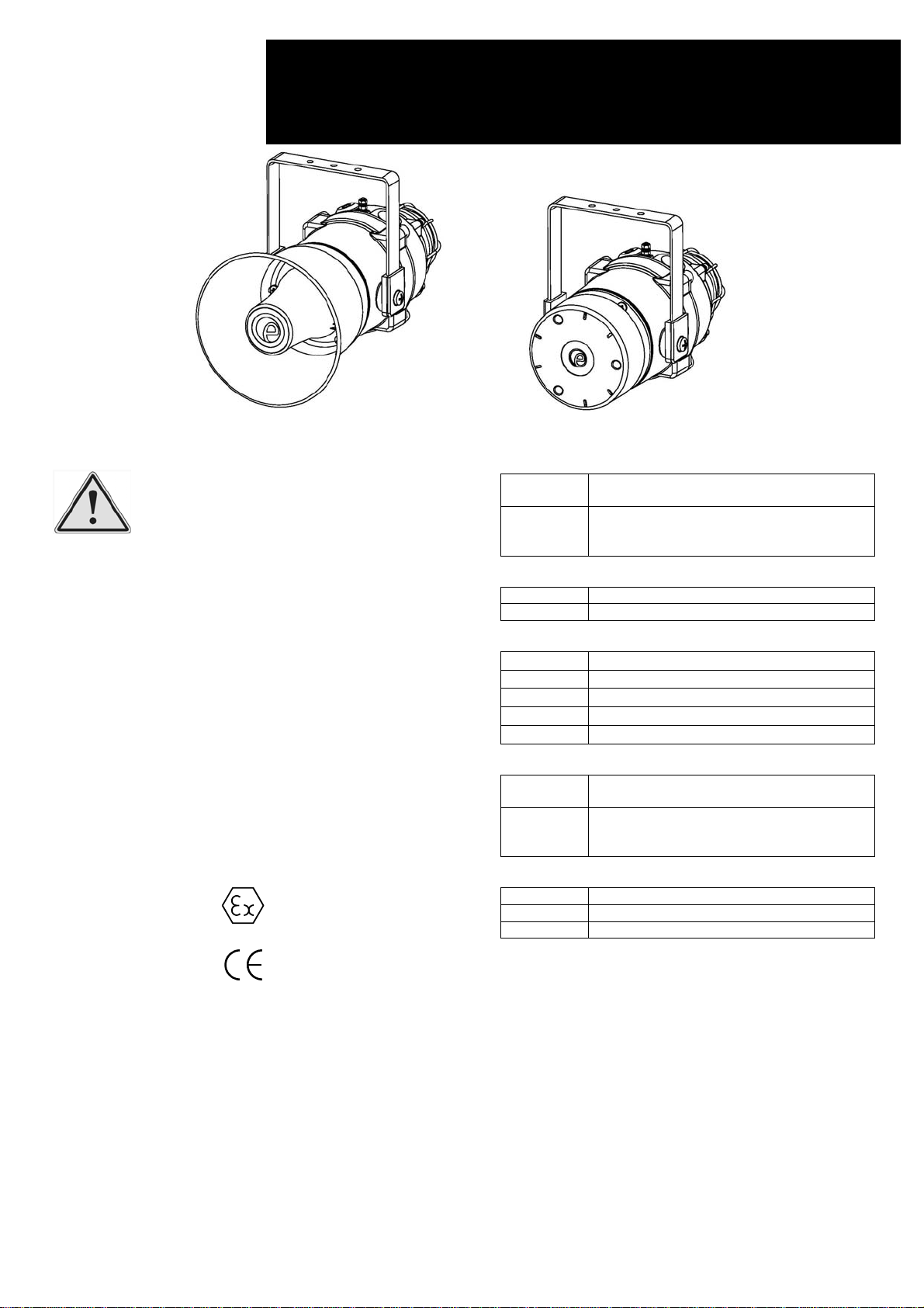
BExCS110-05D-P and BExCS110-05D-R-P Combined Sounder
/ Beacon For use in Flammable Gas and Dust Atmospheres
1) Warnings
DO NOT OPEN WHEN AN EXPLOSIVE
ATMOSPHERE IS PRESENT
DO NOT OPEN WHEN ENERGIZED
POTENTIAL ELECTROSTATIC CHARGING
HAZARD
COVER BOLTS CLASS A4-80
USE HEAT RESISTING CABLES AND CABLE
GLANDS (RATED 110°C) AT AMB.
TEMPERATURES OVER 40°C
2) Rating & Marking Information
All units have a rating label, which carries the following
important information: -
Model No.: BExCS110-05D-P or BExCS110-05D-R-P
Input Voltage: DC Units 12V or 24V or 48V
AC Units 115V or 230V
BExCS110-05D-P or BExCS110-05D-R-P Codes:
Ex d IIB T5 Gb Ta. -50°C to +40°C
Ex d IIB T4 Gb Ta. -50°C to +70°C
Ex tb IIIC T110°C Db Ta. -50°C to +55°C
Ex tb IIIC T125°C Db Ta. -50°C to +70°C
Certificate No. KEMA 01ATEX2223X
IECEx KEM 10.0025X
The units can be installed in locations with the following
conditions:
Area Classification Gas:
Zone 1 Explosive gas air mixture likely to occur in
normal operation.
Zone 2
Explosive gas atmosphere not likely to
occur in normal operation but may be
present for short periods.
Gas Groupings:
Group IIA Propane
Group IIB Ethylene
Temperature Classification:
T1 450ºC
T2 300ºC
T3 200ºC
T4 135ºC
T5 100ºC (up to 40°C ambient)
Area Classification Dust:
Zone 21 Explosive dust air mixture likely to occur in
normal operation.
Zone 22
Explosive dust air mixture not likely to
occur in normal operation, and if it does, it
will only exist for a short time.
Dust Groupings:
Group IIIA Combustible Dusts
Group IIIB Non-Conductive Dust
Group IIIC Conductive Dust
Maximum Surface Temperature for Dust Applications:
110ºC at +55 ºC ambient
125 ºC at +70 ºC ambient
IP Rating: IP66/67 to EN/IEC60529 and IP6X to
EN/IEC60079-0, EN/IEC60079-31
Equipment Category: 2G / 2D
Equipment Protection Level: Gb / Db
Ambient Temperature Range:
-50°C to +70°C Gas Groups IIA and IIB
-50°C to +70°C Dust Groups IIIA, IIIB and IIIC
0518
II 2G
II 2D
Epsilon x
Equipment Group and
Category:
CE Marking
Notified Body No.
BExCS110-05D-P BExCS110-05D-R-P
www.acornfiresecurity.com
www.acornfiresecurity.com

3) Type Approval Standards
The combined sounder beacon carries an EC Type
Examination Certificate and IECEx Certificate of Conformity,
and have been certified to comply with the following
standards:
EN60079-0:2012+A11:2013 / IEC60079-0:2011 (Ed 6):
Explosive Atmospheres - Equipment. General requirements
EN60079-1:2007 / IEC60079-1:2007 (Ed 6):
Explosive Atmospheres - Equipment protection by flameproof
enclosures "d"
EN 60079-31:2014 / IEC60079-31:2013 (Ed 2):
Explosive Atmospheres - Equipment dust ignition protection
by enclosure "t"
4) Installation Requirements
The combined sounder beacon must only be installed by
suitably qualified personnel in accordance with the latest
issues of the relevant standards:
EN60079-14 / IEC60079-14: Explosive atmospheres -
Electrical installations design, selection and erection
EN60079-10-1 / IEC60079-10-1: Explosive atmospheres -
Classification of areas. Explosive gas atmospheres
EN60079-10-2 / IEC60079-10-2: Explosive atmospheres –
Classification of areas. Explosive dust atmospheres
The installation of the combined sounder beacon must also
be in accordance with any local codes that may apply and
should only be carried out by a competent electrical engineer
who has the necessary training.
5) Special Conditions of Use
Repair of the flamepath / flameproof joints is not permitted.
The enclosure is non-conducting and may generate an
ignition-capable level of electrostatic charges under certain
extreme conditions (such as high-pressure steam). The user
should ensure that the equipment is not installed in a location
where it may be subjected to external conditions that might
cause a build-up of electrostatic charges on non-conducting
surfaces.
Additionally, cleaning of the equipment should be done only
with a damp cloth.
6) Location and Mounting
The location of the combined sounder beacon should be
made with due regard to the area over which the warning
signal must be visible. They should only be fixed to services
that can carry the weight of the unit.
The BEx combined sounder beacon should be secured to
any flat surface using the three 7mm fixing holes on the
stainless steel U shaped mounting bracket. See Figure 1.
The required angle can be achieved by loosening the two
large bracket screws in the side of the unit, which allow
adjustment of the combined sounder beacon in steps of 18°.
On completion of the installation then two large bracket
adjustment screws on the side of the unit must be fully
tightened to ensure that the unit cannot move in service.
Fig. 1 Fixing Location for Combined Flare
Fig. 1 Fixing Location for Combined Radial
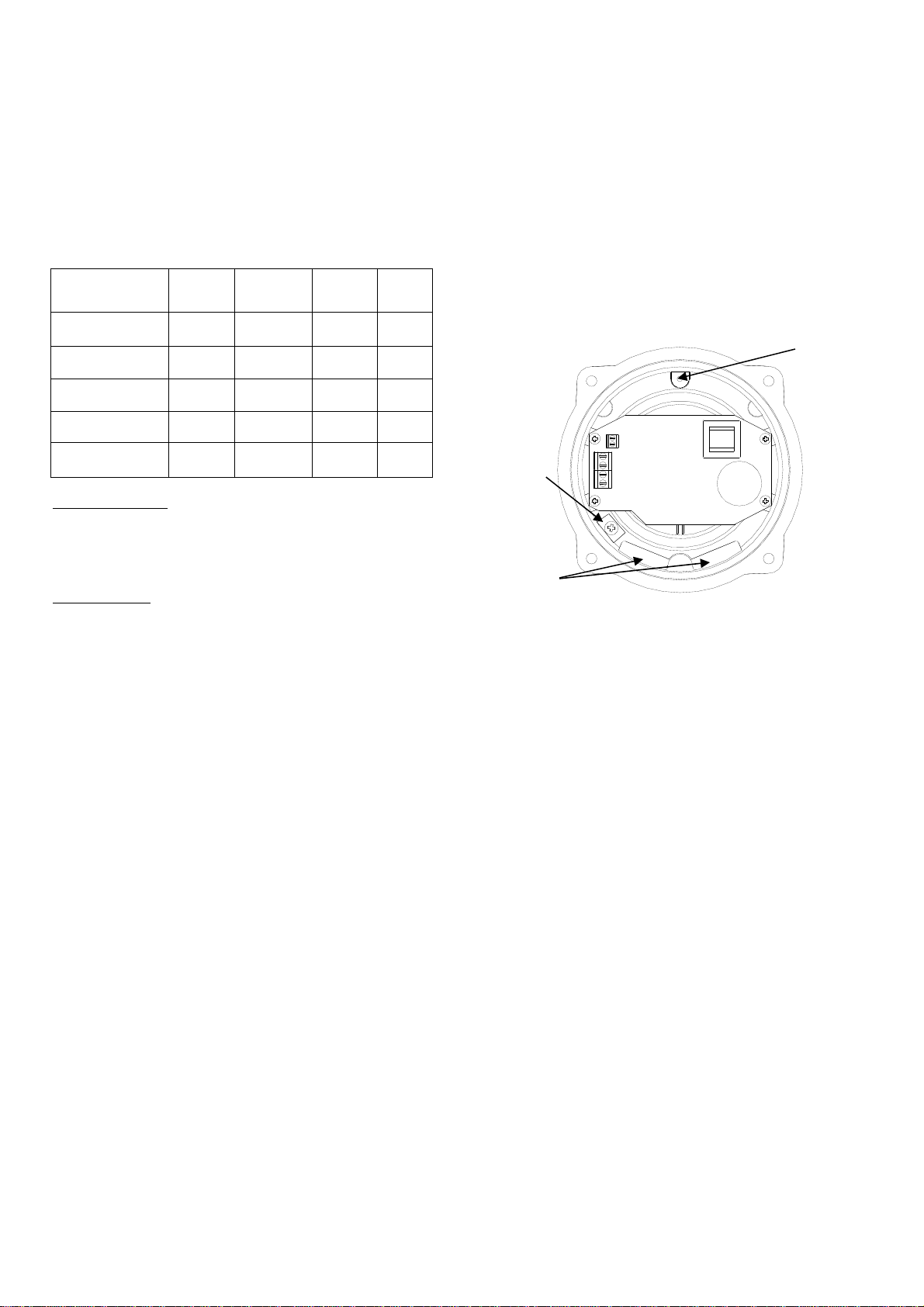
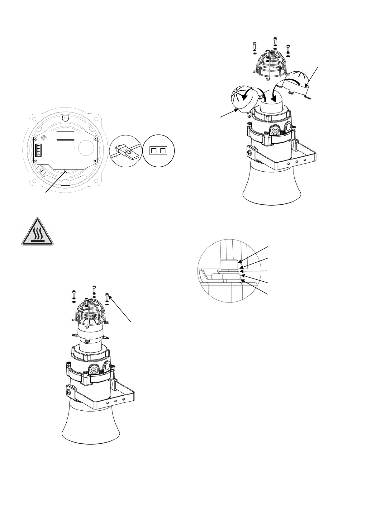
7) Access to the Flameproof Enclosure
To access the Ex d chamber, remove the four M6 hexagon
socket head screws and withdraw the flameproof cover taking
extreme care not to damage the flameproof joints in the
process. M6 cover screws are Class A4-80 stainless steel
and only screws of this category can be used for the
enclosure.
Fig. 2 Accessing the Explosion proof Enclosure.
On completion of the installation, the flameproof joints should
be inspected to ensure that they are clean and that they have
not been damaged during installation.
Check that the earth bonding wire between the two castings
is secure and the ‘O’ ring seal is in place. When replacing the
flameproof cover casting ensure that it is square with the
flameproof chamber casting before inserting. Carefully push
the cover in place allowing time for the air to be expelled.
Only after the cover is fully in place should the four M6
Stainless Steel A4-80 cover bolts and their spring washer be
inserted and tightened down. If the cover jams while it is
being inserted, carefully remove it and try again. Never use
the cover bolts to force the cover into position.
Warning – Hot surfaces. External surfaces
and internal components may be hot after
operation, take care when handling the
equipment.
Warning – High voltage may be present,
risk of electric shock. DO NOT open when
energised, disconnect power before
opening.
(Appropriate cable
glands to be
customer supplied)
Flameproof
cover
M6
Cover
Screws
M6 Spring
Washer
Beacon
Section
Sounder
Section
www.acornfiresecurity.com
www.acornfiresecurity.com
8) Power Supply Selection
It is important that a suitable power supply is used to run the
equipment. The power supply selected must have the
necessary capacity to provide the input current to all of the
units.
The following table shows the input current taken by the
various combined sounder beacons and shows the maximum
voltage at which the combined sounder beacons can be
operated:
Sounder Section
The input current to the sounder section will vary according to
the voltage input level and the frequency of the tone selected.
The current levels shown above are for the 440Hz
Continuous tone @ nominal input voltage.
Beacon Section
The input current to the beacon section will vary according to
the voltage input level. The current levels shown above are
for nominal input voltage.
9) Selection of Cable. Cable Glands, Blanking
Elements & Adapters
When selecting the cable size, consideration must be given
to the input current that each unit draws (see table above),
the number of combined sounder beacons on the line and the
length of the cable runs. The cable size selected must have
the necessary capacity to provide the input current to all of
the combined sounder beacons connected to the line.
For ambient temperatures over +40ºC the cable entry
temperature may exceed +70ºC and therefore suitable heat
resisting cables and cable glands must be used, with a rated
service temperature of at least 110ºC
The dual cable gland entries have an M20 x 1.5 entry thread.
To maintain the ingress protection rating and mode of
protection, the cable entries must be fitted with suitably rated
ATEX / IECEx certified cable glands and/or suitably rated
ATEX / IECEx certified blanking devices during installation
according to EN / IEC60079-14.
If a high IP (Ingress Protection) rating is required then a
suitable sealing washer must be fitted under the cable glands
or blanking plugs.
For use in explosive dust atmospheres, a minimum ingress
protection rating of IP6X must be maintained.
The BEx combined sounder beacon range can be supplied
with the following types of adapters:
M20 to ½” NPT
M20 to ¾” NPT
M20 to M25
It is important to note that stopping plugs cannot be fitted
onto adapters, only directly onto the M20 entries.
Any other adapters used must be suitably rated and ATEX /
IECEx certified adapters.
10) Earthing
Both AC and DC combined sounder beacon units must be
connected to an earth. The units are provided with internal
and external earth terminals which are both located on the
terminal chamber section of the unit.
Fig. 3 Internal View of Cover
When using the internal earth terminal ensure that the
stainless steel M4 flat washer is between the incoming earth
wire and the enclosure.
Internal earthing connections should be made to the Internal
Earth terminal in the base of the housing using a ring crimp
terminal to secure the earth conductor under the earth clamp.
The earth conductor should be at least equal in size and
rating to the incoming power conductors.
External earthing connections should be made to the M5
earth stud, using a ring crimp terminal to secure the earth
conductor to the earth stud. The external earth conductor
should be at least 4mm² in size.
11) Cable Connections
The combined sounder beacon unit BExCS110-05D has
separate printed circuit boards in the sounder and beacon
sections. The terminals for the sounder are on the printed
circuit board in the sounder section and the terminals for the
beacon are on the printed circuit board in the beacon section
(see figures 4a, 4b, 6a and 6b). See section 7 of this manual
for access to the enclosure. See section 12 and 13 for AC
and DC wiring diagrams respectively.
Wires having a cross sectional area between 0.5 mm² to
2.5mm² can be connected to each terminal way. If an input
and output wire is required the 2-off Live/Neutral or +/-
terminals can be used. If fitting 2-off wires to one terminal
way the sum of the 2-off wires must be a maximum cross
sectional area of 2.5mm². Strip wires to 8mm. Wires may also
be fitted using ferrules. Terminal screws need to be tightened
down with a tightening torque of 0.45 Nm / 5 Lb-in. When
connecting wires to the terminals great care should be taken
Model No. Nominal
I/P
Voltage
Sounder
Current Beacon
Current
Max.
I/P
Volts
BExCS110-05D-P
DC012 12Vdc 195mA 750mA 14V
BExCS110-05D-P
DC024 24Vdc 265mA 300mA 28V
BExCS110-05D-P
DC048 48Vdc 130mA 180mA 54V
BExCS110-05D-P
DC115 115Vac 110mA 140mA 126V
BExCS110-05D-P
AC230 230Vac 56mA 55mA 253V Internal
Earthing
Internal
Bonding
Wire
Terminal
2-off M20
Cable
Entries
www.acornfiresecurity.com
www.acornfiresecurity.com
to dress the wires so that when the cover is inserted into the
chamber the wires do not exert excess pressure on the
terminal blocks. This is particularly important when using
cables with large cross sectional areas such as 2.5mm².
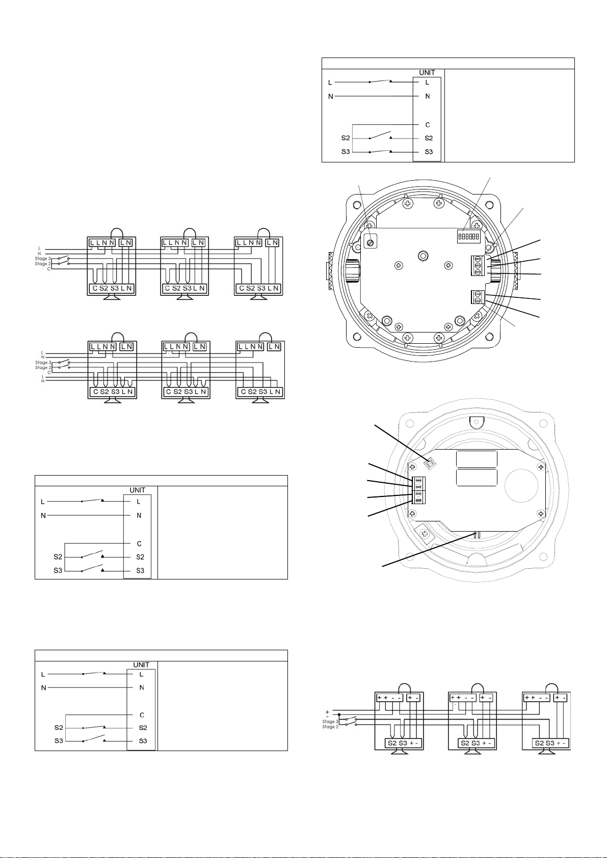
12) AC Wiring
A 2-way terminal block is provided on the AC Sounder for
power. There are 1-off Live and 1-off Neutral terminals in
total. A 3-way terminal is provided for stage switching. There
are 1-off stage 2, 1-off stage 3 and 1-off common terminals in
total. A 4-way terminal block is provided on the AC beacon
for power. There are 2-off Live and 2-off Neutral terminals in
total.
12.1 Wiring Diagrams
Fig 3a. BExCS110-05D AC Simplified Block Diagram for
simultaneous operation
Fig 3b. BExCS110-05D AC Simplified Block Diagram for
independent operation
12.2 Sounder Stage Switching
12.2.1 Units First Stage Tones
Stage one (S1) Operation
Simply connect the supply
voltage to the L and N supply
terminals, (see fig. 4).
12.2.2 AC Units Second and Third Stage Tone
Selection
To select the second and third stage tones on the BExCS110
AC sounder.
Stage two (S2) Operation
Power L and N, link the
Common-C and S2 terminal.
Dip switch alters stage 2
tone.
Stage three (S3) Operation
Power L and N, link the
Common-C and S3
terminals.
Dip switch alters stage 3
tone.
Fig. 4a Sounder AC Terminals
Fig. 4a Beacon AC Terminals
13) DC Wiring
A 4-way terminal block is provided on the DC Sounder. There
are 1-off +ve, 1-off -ve, 1-off stage 2 and 1-off stage 3
terminals in total.
13.1 Wiring Diagrams
Fig 5a. BExCS110-05D AC Simplified Block Diagram for
simultaneous operation (negative switching)
DIP Switch
Volume Control
Stage
Terminals
AC
Terminals
S2
S3
C
N
L
L
L
N
N
Interconnecting Terminals
to sounder PCB
(simultaneous
mode of operation)
Flip / Flop
Pin Header
www.acornfiresecurity.com
www.acornfiresecurity.com
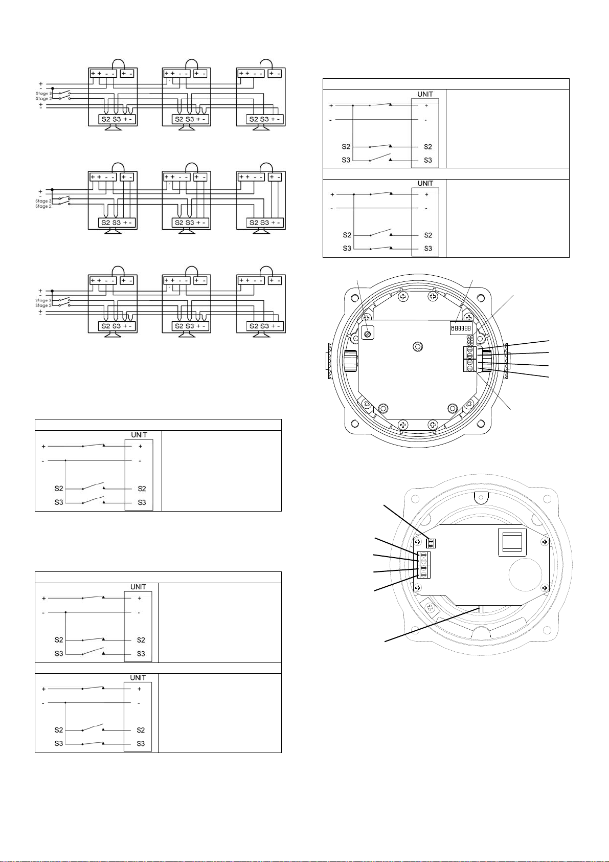
Fig 5b. BExCS110-05D AC Simplified Block Diagram for
independent operation (negative switching)
Fig 6a. BExCS110-05D AC Simplified Block Diagram for
simultaneous operation (positive switching)
Fig 6b. BExCS110-05D AC Simplified Block Diagram for
independent operation (positive switching)
13.2 Stage Switching
13.2.1 Units First Stage Tones
Stage one (S1) Operation
Simply connect the supply
voltage to the + and -
supply terminals, (see fig.
6).
13.2.2 DC Units Second and Third Stage Tone
Selection
For units set up for –ve switching (default setting):
Stage two (S2) Operation
Power +ve and –ve, link a -
ve supply line to the S2
terminal.
Dip switch alters stage 2
tone.
Stage three (S3) Operation
Power +ve and –ve, link a -
ve supply line to the S3
terminal.
Dip switch alters stage 3
tone.
For units set up for +ve switching (refer to 13.3):
Stage two (S2) Operation
Power +ve and –ve, link a
+ve supply line to the S2
terminal.
Dip switch alters stage 2
tone.
Stage three (S3) Operation
Power +ve and –ve, link a
+ve supply line to the S3
terminal.
Dip switch alters stage 3
tone.
Fig. 6a DC Terminals
Fig. 6b Beacon DC Terminals
13.3 Stage Switching Polarity (DC Units
Only)
The BExCS110-05D DC sounders has the facility to use
either +ve or –ve switching to change the tone to the second
and third stages. Negative switching is the default setting. For
–ve switching connect the two headers on the pcb to the left-
hand (marked –ve) and centre pins. For +ve switching
connect the headers to the right hand (marked +ve) and the
centre pins. (Refer to Fig. 7)
Volume Control DIP Switch
DC Terminals
Stage Headers
S2
S3
-
+
-
-
+
+
Flip / Flop
Pin Header
Interconnecting Terminals
to sounder PCB
(simultaneous
mode of operation)
www.acornfiresecurity.com
www.acornfiresecurity.com
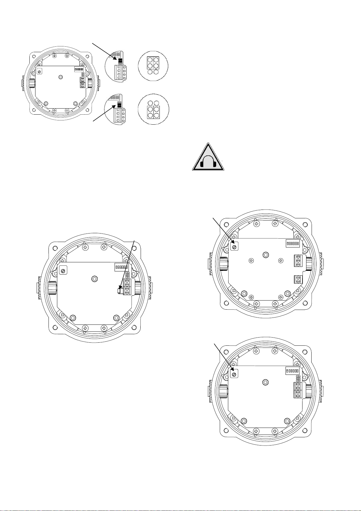
Fig. 7 Stage Switching Polarity
13.4 Line Monitoring
On BExCS110-05D DC units, dc reverse line monitoring can
be used if required. All DC sounders have a blocking diode
fitted in their supply input lines. An end of line monitoring
diode or an end of line monitoring resistor can be connected
across the +ve and –ve terminals. If an end of line resistor is
used it must have a minimum resistance value of 3k3Ωand a
minimum power rating of 0.5 watts or a minimum resistance
value of 500Ωand a minimum power rating of 2 watts.
The resistor must be connected directly across the +ve and -
ve terminals as shown in the following drawing. The resistor
leads should be kept as short as possible.
Fig. 8 End of Line Resistor Placement
14) Wiring the combined sounder/beacon for
simultaneous operation
The sounder and beacon sections can be wired to the same
input supply so that they operate simultaneously or they can
be wired to separate input supplies so they can be operated
independently (see fig. 3, 5 & 6).
If the sounder and beacon sections are connected to the
same input supply. The incoming cables should be connected
to the input terminals on the beacon board and the two link
wires, that are supplied with the unit, should be used to link
the supply from the interconnecting terminals on the beacon
board down to the supply terminals on the sounder board.
15) Settings
15.1 Tone Selection
The sounders have 32 different tones that can be selected for
the first stage alarm. The sounders can then be switched to
sound second and third stage alarm tones. The tones are
selected by operation of a DIP switch on the pcb for both DC
and AC units. The tone table on page seven shows the
switch positions for the 32 tones and which tones are
available for the second and third stages. To operate the
sounder on stage one simply connect the supply voltage to
the normal supply terminals (+ve and –ve for DC units, L and
N for AC units).
15.2 Volume Control
The output level of the BEx sounder can be set by adjusting
the volume control potentiometer (see Fig 9) with the
exception of 12V DC units. For maximum output, set the
potentiometer fully clockwise.
BExCS110-05D AC
BExCS110-05D DC
Fig. 9 Location of Volume Control Potentiometer
Warning - High noise levels above 85dB(A)
during operation. High levels of noise may
cause hearing loss, wear suitable ear
protection when equipment is in operation.
End of Line Resisto
r
Volume Control
Potentiometer
Volume Control
Potentiometer
Negative Switching Activated
Positive Switching Activated
Header Pin Location
Header Pin Location
-
+
-
+
www.acornfiresecurity.com
www.acornfiresecurity.com
15.3 Flip/Flop Operation
Two units can be mounted close to each other to form a flip-
flop operation, where the beacons will flash alternately. To
achieve this mode of operation, fit a pin header to the flip-
flop header pins on the electronics board, i.e. the two header
pins are shorted together, on one of the two beacons. The
first flash on the beacon that has the header fitted will be
delayed by ½ second. The two beacons will then flash
alternately every ½ a second.
16) Interchangeable & Spare Parts
The beacon cover is interchangeable, contact E2S Ltd for a
replacement cover available in various colours.
To change the cover, unscrew the M5 socket head screws
and remove the M5 screws, M5 spring & flat washers.
Fig. 11 Removal of cover
Remove the guard and replace the old cover with the new
cover.
Fig. 12 Changing of cover
Fit the guard back on to the cover and casting, align the
holes of the guard, cover and casting. To reattach the cover,
the fixings MUST be in the order shown in figure 12.
Fig. 13 Cover and Guard Fixtures
17) Maintenance, Overhaul & Repair
Maintenance, repair and overhaul of the equipment should
only be carried out by suitably qualified personnel in
accordance with the current relevant standards:
EN60079-19
IEC60079-19
Explosive atmospheres - Equipment repair,
overhaul and reclamation
EN 60079-17
IEC60079-17
Explosive atmospheres - Electrical
installations inspection and maintenance
To avoid a possible ELECTROSTACTIC CHARGE the unit
must only be cleaned with a damp cloth.
Units must not be opened while an explosive atmosphere is
present.
If opening the unit during maintenance operations a clean
environment must be maintained and any dust layer removed
prior to opening the unit.
Flameproof threaded joints and cemented joints are not
intended to be repaired.
Warning – Hot surfaces. External surfaces
and internal components may be hot after
operation, take care when handling the
equipment.
Header Pins shorted
Flip / Flop Pin Header
M5x16 Hex Socket Screw
M5 Spring Washer
M5 Plain Washer
Guard
Cover
M5x16 Hex
Socket Screw
Old
Cover
New
Cover
www.acornfiresecurity.com
www.acornfiresecurity.com

Tone Selection
DIP Switch
Settings
Stage Selection
Stage 1 Frequency Description 1 2 3 4 5 Stage 2 Stage 3
1 Continuous 1000Hz Toxic Gas Alarm 0 0 0 0 0 Tone 31 Tone 11
2 Alternating 800/1000Hz at 0.25s intervals 1 0 0 0 0 Tone 17 Tone 5
3 Slow Whoop 500/1200Hz at 0.3Hz with 0.5s gap repeated 0 1 0 0 0 Tone 2 Tone 5
4 Sweeping 800/1000 at 1Hz 1 1 0 0 0 Tone 6 Tone 5
5 Continuous at 2400Hz 0 0 1 0 0 Tone 3 Tone 27
6 Sweeping 2400/2900Hz at 7Hz 1 0 1 0 0 Tone 7 Tone 5
7 Sweeping 2400/2900Hz at 1Hz 0 1 1 0 0 Tone 10 Tone 5
8 Siren 500/1200/500Hz at 0.3Hz 1 1 1 0 0 Tone 2 Tone 5
9 Sawtooth 1200/500Hz at 1Hz 0 0 0 1 0 Tone 15 Tone 2
10 Alternating 2400/2900Hz at 2Hz 1 0 0 1 0 Tone 7 Tone 5
11 Intermittent 1000Hz at 0.5Hz General alarm 0 1 0 1 0 Tone 31 Tone 1
12 Alternating 800/1000Hz at 0.875Hz 1 1 0 1 0 Tone 4 Tone 5
13 Intermittent 2400Hz at 1Hz 0 0 1 1 0 Tone 15 Tone 5
14 Intermittent 800Hz 0.25s on 1s off 1 0 1 1 0 Tone 4 Tone 5
15 Continuous at 800Hz 0 1 1 1 0 Tone 2 Tone 5
16 Intermittent 660Hz 150mS on, 150mS off 1 1 1 1 0 Tone 18 Tone 5
17 Alternating 544Hz (100mS)/440Hz(400mS) 0 0 0 0 1 Tone 2 Tone 27
18 Intermittent 660Hz 1.8s on, 1.8s off 1 0 0 0 1 Tone 2 Tone 5
19 1400Hz to 1600Hz sweep up over 1s - 1600Hz to 1400Hz
sweep down over 0.5s
0 1 0 0 1 Tone 2 Tone 5
20 Continuous 660Hz 1 1 0 0 1 Tone 2 Tone 5
21 Alternating 554/440Hz at 1Hz 0 0 1 0 1 Tone 2 Tone 5
22 Intermittent 554Hz at 0.875Hz 1 0 1 0 1 Tone 2 Tone 5
23 800Hz pulsing at 2Hz 0 1 1 0 1 Tone 6 Tone 5
24 Sweeping 800/1000Hz at 50Hz 1 1 1 0 1 Tone 29 Tone 5
25 Sweeping 2400/2900Hz at 50Hz 0 0 0 1 1 Tone 29 Tone 5
26 Simulated bell sound 1 0 0 1 1 Tone 2 Tone 1
27 Continuous 554Hz 0 1 0 1 1 Tone 26 Tone 5
28 Continuous 440Hz 1 1 0 1 1 Tone 2 Tone 5
29 Sweeping 800/1000Hz at 7Hz 0 0 1 1 1 Tone 7 Tone 5
30 420Hz repeating 0.625s on, 0.625s off Australian alert signal 1 0 1 1 1 Tone 32 Tone 5
31 1200/500Hz at 1 Hz Prepare to Abandon Platform 0 1 1 1 1 Tone 11 Tone 1
32 Sweeping 500/1200Hz 3.75s on, 0.25s off 15Hz 1 1 1 1 1 Tone 26 Tone 1
www.acornfiresecurity.com
www.acornfiresecurity.com
This manual suits for next models
4
Table of contents
Popular Marine Equipment manuals by other brands

MZ electronic
MZ electronic NC-360 Installation and user manual

Simrad
Simrad ES60 - DATASHEET REV A release note

Lowrance
Lowrance HDS Gen3 Touch quick start guide

Observator Instruments
Observator Instruments OMC-131 Installation and technical manual

Garmin
Garmin 600 T-TOP installation guide

RS Aqua
RS Aqua WaveRadar Rex Series Faq

Garmin
Garmin Gladiator TR-1 Installation setup manual

Venitem
Venitem TRIADE F24 quick start guide

Humminbird
Humminbird HDR 600 Operation manual

Shenzhen Waytronic Electronics
Shenzhen Waytronic Electronics MicroSound V16.00 quick start guide

Garmin
Garmin Gladiator TR-1 owner's manual

B&G
B&G RAM T0 user manual


