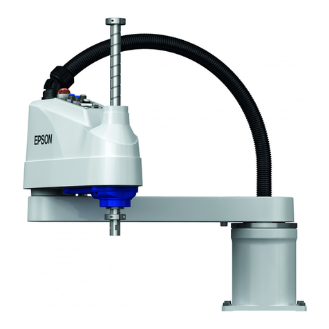
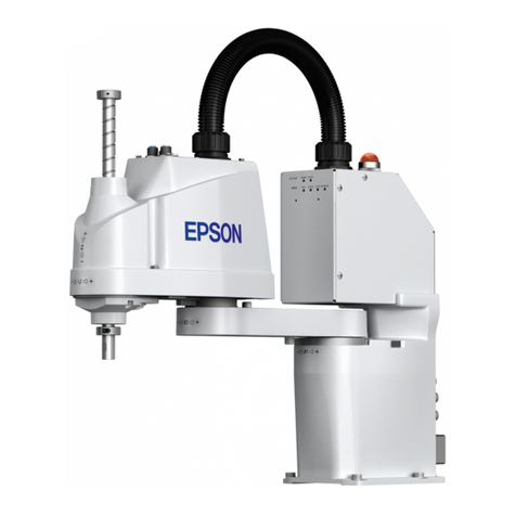
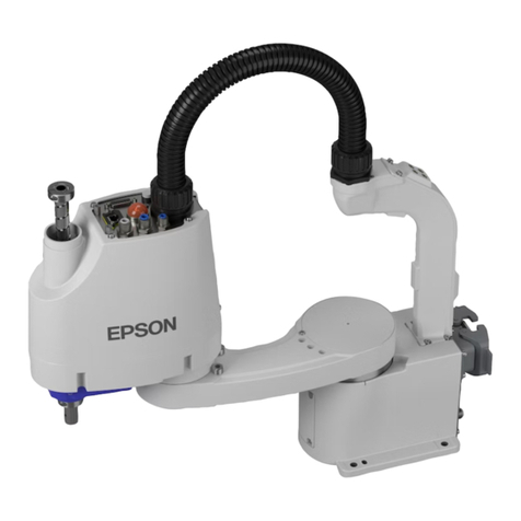
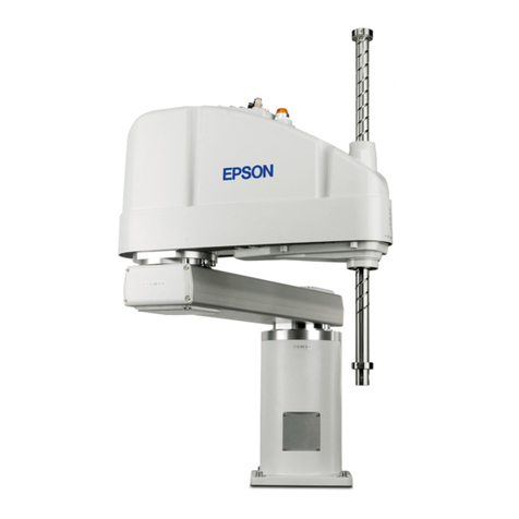
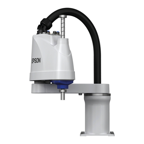
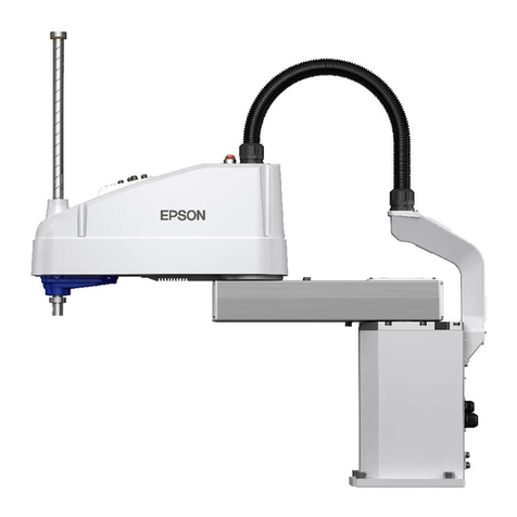
Epson ES Series User manual

ES/EL series
Rev.9 EM019R893F
SCARA ROBOT
MANIPULATOR MANUAL

MANIPULATOR MANUALES/EL seriesRev.9

i
SCARA ROBOT
ES / EL series Manipulator manual
Rev.9
Copyright 1997-2001 SEIKO EPSON CORPORATION. All rights reserved.

ii
WARRANTY
The robot and its optional parts are shipped to our customers only after being subjected to
the strictest quality controls, tests and inspections to certify its compliance with our high
performance standards.
Product malfunctions resulting from normal handling or operation will be repaired free of
charge during the normal warranty period. (Please ask your Regional Sales Office for
warranty period information.)
However, customers will be charged for repairs in the following cases (even if they occur
during the warranty period):
1. Damage or malfunction caused by improper use which is not described in the manual,
or careless use.
2. Malfunctions caused by customers’ unauthorized disassembly.
3. Damage due to improper adjustments or unauthorized repair attempts.
4. Damage caused by natural disasters such as earthquake, flood, etc.
Warnings, Cautions, Usage:
1. If the robot or associated equipment is used outside of the usage conditions and
product specifications described in the manuals, this warranty is void.
2. If you do not follow the WARNINGS and CAUTIONS in this manual, we cannot be
responsible for any malfunction or accident, even if the result is injury or death.
3. We cannot foresee all possible dangers and consequences. Therefore, this manual
cannot warn the user of all possible hazards.

iii
TRADEMARKS
Microsoft is a registered trademark and Windows and Windows logo are registered
trademarks of the Microsoft Corporation.
Other brand and product names are trademarks or registered trademarks of the respective
holders.
NOTICE
No part of this manual may be copied or reproduced without authorization.
The content of this manual is subject to change without notice.
We ask that you please notify us if you should find any errors in this manual or if you have any
comments regarding its content.
Please direct any inquiries about the use of this manual to:
ES / EL series manipulator manual
SEIKO EPSON CORPORATION
Sales Engineering Group
TEL : 81-266-24-2004
FAX : 81-266-24-2017

iv
SAFETY PRECAUTIONS
Please carefully read this and other related manuals before and while using the equipment.
Keep this manual in a handy location for easy access at all times.
WARNING
This sign indicates that a danger of serious
injury or death will exist if theses instructions
are not followed.
CAUTION
This sign indicates that ignoring these
instructions may cause harm to people or
physical damage to equipment and facilities.
WARNING
The robot system manufacturer/supplier must design and construct robot systems
in accordance with the principles described in the Safety chapter of the “User’s
Guide” or “SRC5**/SPEL 95 Introduction manual” or “User’s manual”. Please
read these manual first.
This robot has been designed and manufactured strictly for use in a normal indoor
environment. Do not use the robot in an environment that exceeds the conditions
set forth in the manuals for the manipulator and controller.
Do not use the robot outside of the usage conditions and product specifications
described in the manuals. Doing so will not only adversely affect the life of the
product, but may also present a serious safety problem.
Only trained personnel should be allowed to design, install, operate, perform
function testing, and maintain this manipulator and the robot system.
Trained personnel are those who have taken a robot training course (held by the
dealer on a regular basis) or those who have carefully read the manuals and have
equivalent knowledge and skill.

v
FOREWORD
This manual contains information that you need to know to use the ES / EL series
manipulator correctly. Please thoroughly read this and other related manuals before using
the equipment.
This manipulator can be used with the following EPSON robot controllers:
• EPSON RC+
• SPEL 95 / SRC5**
• SRC-3**
Use the descriptions for the controller used with your manipulator, indicated by the
following icons:
Procedure when using EPSON RC+ Robot Control System.
Procedure when using SPEL 95 / SRC5** controllers.
Procedure when using SRC-3** controllers.
If the manipulator is a Clean model, refer to the chapters Clean Model and Clean Model
Maintenance, which provide a summary of differences between the Clean and Standard
specifications.
If the manipulator is a Protected model, refer to the chapters Protected Model and Protected
Model Maintenance, which provide a summary of differences between the Protected and
Standard specifications.
An “axis” of the manipulator is referred to as a “joint” in this manual.
RC+
300
SPEL 95
300

vi
SERVICE CENTER
Contact the following service center for robot repairs, inspections or adjustments.
Please have the model name, “Serial No.” or “M.CODE”, software version and a
description of the problem ready when you call.
If service center information is not indicated here, please contact the supplier office for your
region as listed in the following SUPPLIERS section.
SUPPLIERS
Japan & Others SEIKO EPSON CORPORATION
Okaya Plant No. 2
1-16-15, Daiei-cho
Okaya-shi, Nagano-ken, 394-0025
Japan
TEL: 81-266-23-0020 (switchboard)
81-266-24-2004 (direct)
FAX: 81-266-24-2017
North & South EPSON AMERICA, INC.
America Factory Automation/Robotics
18300 Central Avenue
Carson, CA 90746
TEL: (562) 290-5900
FAX: (562) 290-5999
E-MAIL: info@robots.epson.com
Europe EPSON DEUTSCHLAND GmbH
Factory Automation Division
Zuelpicher Str. 6 D-40546 Duesseldorf
TEL: (++) 49 - 211 - 5603 391 (Inside Sales)
FAX: (++) 49 - 211 - 5603 444

vii
TABLE OF CONTENTS
Part 1: Setup & Operation
1. Manipulator Part Names.............................................................. 3
2. Installation Requirements........................................................... 5
2.1 Environmental conditions........................................................................5
2.2 Installation area.......................................................................................5
2.3 Base Table ..............................................................................................6
2.4 Pre-installation safety precautions ..........................................................8
3. Installation.................................................................................... 9
3.1 Unpacking...............................................................................................9
3.2 Installation method................................................................................10
3.3 Connecting the cables ..........................................................................12
3.4 Safety precautions after installation ......................................................14
3.5 Relocating the manipulator ...................................................................16
4. User Wires and Pneumatic Tubes ............................................ 17
5. End Effectors ............................................................................. 19
5.1 Attaching an end effector ......................................................................19
Wire and tube layout ...................................................................................21
5.2 The end effector and acceleration / deceleration..................................22
Setting WEIGHT parameters ......................................................................22
Precautions for auto acceleration / deceleration .........................................25
Moment of inertia and the ACCEL setting ...................................................26
Calculating the moment of inertia................................................................27
Eccentricity of Joint #4 ................................................................................29
6. Attaching a Camera, Valve, and Other Devices....................... 31
7. External Dimensions ................................................................. 33
8. Motion Range and Robot Coordinates..................................... 35
8.1 Standard motion range .........................................................................35
8.2 Pulse range...........................................................................................41
8.3 Changing the motion range ..................................................................44
Methods of setting the motion range...........................................................44
(1) Changing motion range using pulse range ............................................45
(2) Changing motion range using mechanical stops ...................................46
(3) Changing motion range using X, Y limits ...............................................54
9. Emergency Stop......................................................................... 57
10. Specifications .......................................................................... 59
10.1 ES series Standard model specifications ...........................................60
10.2 EL series Standard model specifications............................................61
10.3 Model settings.....................................................................................62
11. Clean Model.............................................................................. 63
11.1 Manipulator part names ......................................................................63
11.2 Installation method ..............................................................................64
11.3 Exhaust System ..................................................................................64
11.4 External dimensions............................................................................65
11.5 Additional specifications......................................................................67

viii
12. Protected Model ...................................................................... 69
12.1 Manipulator part names ..................................................................... 70
12.2 Environmental conditions ................................................................... 71
General environmental conditions...............................................................71
Special environmental conditions ...............................................................72
12.3 Connecting the cables........................................................................ 73
12.4 User wires and pneumatic tubes........................................................ 74
12.5 External dimensions........................................................................... 76
12.6 Additional specifications..................................................................... 78
Part 2: Maintenance
Maintenance Safety Precautions ................................................. 81
1. General Maintenance ................................................................ 83
1.1 Maintenance Inspection Schedule ....................................................... 83
1.2 Inspections ........................................................................................... 84
1.3 Lubrication............................................................................................ 86
1.4 Tightening Torque of Bolts.................................................................... 86
1.5 Matching mechanical and electrical origins.......................................... 87
1.6 Differences between ES and EL Series ............................................... 87
1.7 Internal Layout...................................................................................... 88
2. Opening the Covers .................................................................. 89
2.1 Arm Top Cover ..................................................................................... 89
2.2 Arm Bottom Cover................................................................................ 90
2.3 Joint #1 Cover ...................................................................................... 90
2.4 Base Connector Plate .......................................................................... 91
3. Replacing the Cable Unit .......................................................... 93
3.1 Cable Unit Replacement Procedure..................................................... 94
3.2 Wiring Schematic 1 .............................................................................. 98
3.3 Wiring Schematic 2 .............................................................................. 99
4. Connector Pin Assignments................................................... 101
5. Replacing the Motors .............................................................. 107
5.1 Replacing the Joint #1 Motor.............................................................. 108
5.2 Replacing the Joint #2 Motor...............................................................112
5.3 Replacing the Joint #3 Motor...............................................................116
5.4 Replacing the Joint #4 Motor.............................................................. 122
6. Replacing the Reduction Gear Units ..................................... 127
6.1 Replacing the Joint #1 Reduction Gear Unit ...................................... 130
6.2 Replacing the Joint #2 Reduction Gear Unit ...................................... 139
7. Replacing the Brake................................................................ 151
8. Replacing the Timing Belts .................................................... 155
8.1 Replacing the Z belt ........................................................................... 156
8.2 Replacing the U1 Belt......................................................................... 159
8.3 Replacing the U2 Belt......................................................................... 162
9. Replacing the Ball Screw Spline Unit .................................... 167
9.1 Replacing the Ball Screw Spline Unit ................................................. 168
9.2 Greasing the Ball Screw Spline Unit .................................................. 173
10. Replacing the Signal Relay Board ....................................... 175
10.1 Signal Relay Board........................................................................... 175
10.2 Replacing the Lithium Battery .......................................................... 177

ix
11. Calibration .............................................................................. 179
11.1 Calibration for EPSON RC+ Controller .............................................180
Common procedure for calibration............................................................180
Calibrating Joint #3 ...................................................................................182
Calibrating Joint #1, #2, and #4 ................................................................183
Accurate calibration of Joint #2 .................................................................184
11.2 Calibration for SPEL 95 / SRC-5** Controller ...................................186
Common procedure for calibration............................................................186
Calibrating Joint #3 ...................................................................................188
Calibrating Joint #1, #2, and #4 ................................................................189
Accurate calibration of Joint #2 .................................................................190
11.3 Calibration for SRC-3** Controllers...................................................192
Common procedure for calibration............................................................192
Calibrating Axis #3 ....................................................................................194
Calibrating Axes #1, #2, and #4 ................................................................195
Accurate calibration of Axis #2..................................................................196
12. Clean Model Maintenance..................................................... 199
12.1 Greasing the Ball Screw Spline Unit.................................................199
12.2 Replacing the Bellows.......................................................................201
13. Protected Model Maintenance .............................................. 203
13.1 Safety Precautions............................................................................203
13.2 Sealing the Manipulator ....................................................................204
13.3 Internal Layout ..................................................................................206
13.4 Replacing the Cable Unit ..................................................................207
13.5 Wiring Schematic 1........................................................................... 211
13.6 Wiring Schematic 2...........................................................................212
13.7 Greasing the Ball Screw Spline Unit.................................................213
13.8 Replacing the Bellows.......................................................................215
13.9 Replacing the Signal Relay Board ....................................................220
14. Maintenance Part Lists.......................................................... 221
14.1 Maintenance Parts for All Models .....................................................221
14.2 Maintenance Parts for Standard-model............................................222
14.3 Maintenance Parts for Clean-model .................................................222
14.4 Maintenance Parts for Protected-model...........................................223

x

1
Part 1
Setup & Operation
Part 1 contains information for setup and operation of the EPSON
ES and EL Series Manipulators, including:
• Installation
• Safety
• User wiring and pneumatics
• Attaching external devices
• Motion range adjustments
• Specifications

2

Part 1: Setup & Operation 1. Manipulator Part Names
3
1. Manipulator Part Names
The model name of the ES / EL series Manipulator is specified as follows:
ES 55 1 S
Option S: Standard model
C: Clean model *1
P: Protected model *2
Joint #3 stroke 1: 170 mm
3: 320 mm
Arm length 45: 450 mm
55: 550 mm
65: 650 mm
85: 850 mm
Series name ES, EL
*1 If the Manipulator is a Clean model, refer to chapter 11. Clean Model.
*2 If the Manipulator is a Protected model, refer to chapter 12. Protected Model.
Manipulator parts
MT label
M.CODE label
(for SRC-3**)
Joint #1
(rotating)
Joint #2
(rotating)
Joint #3
(up and down)
Joint #4
(rotating)
Arm #1
Arm #2
Base
Cable unit
Shaft
Sensor monitor
Signature label
Fitting for φ6 mm
pneumatic tube
Fitting for φ4 mm
pneumatic tube
Spare
Signal connector
Power connector
User connector
Rear
Figure 1. Manipulator

1. Manipulator Part Names Part 1: Setup & Operation
4

Part 1: Setup & Operation 2. Installation Requirements
5
2. Installation Requirements
2.1 Environmental conditions
A suitable environment is necessary for the manipulator to function properly and safely.
Please install the robot in a place that meets the following requirements.
Ambient temperature 5 to 40°C (with minimum temperature variation)
Ambient relative humidity 10 to 80% (no condensation)
First transient burst noise 2kV max.
Electrostatic noise 6kV max.
Environment Install indoors.
Place in a well-ventilated area.
Keep away from direct sunlight.
Keep away from dust, oily smoke, salinity, metal powder
or other contaminants.
Keep away from flammable or corrosive solvents and
gases.
Keep away from water.
Keep away from shocks or vibrations.
Keep away from sources of electric noise.
The standard manipulator is not suitable for operation in
harsh environments such as painting, etc. Contact the
service center or the suppliers for details.
2.2 Installation area
In addition to the space necessary for installing the manipulator, controller and peripheral
devices, you will need to have, at a minimum, the following:
Space for teaching points.
Space for performing maintenance and inspections.
Space for cables.
The minimum bend radius of the power cable is 130 mm. When you install the
manipulator make certain to maintain sufficient distance from obstacles. Leave enough
space for other cables also, so that they don’t have to be bent at extreme angles.
NOTE

2. Installation Requirements Part 1: Setup & Operation
6
2.3 Base Table
A base table for anchoring the manipulator is not supplied. Users must make or obtain
such a table independently. The size and shape of the base table differs depending on the
robot’s application. For your reference, when designing or obtaining a base table, we have
listed some manipulator requirements.
If the controller will be mounted inside the table, please refer to the controller manual or
user’s guide, which describes space requirements and environmental conditions.
Area limited by
mechanical stop
for
Joint #3
Standard range of the manipulator ES45** ES55** ES65** EL65** EL85**
A(arm #1 length)
B(arm #2 length)
C
D(motion range of the Joint #1)
E(motion range of the Joint #2)
F
G(range to the stop of Joint #1)
H(range to the stop of Joint #2)
215 mm
235 mm
156 mm
125 °
140 °
136 mm
130 °
145 °
315 mm
235 mm
203 mm
125 °
140 °
182 mm
130 °
145 °
415 mm
235 mm
280 mm
125 °
140 °
260 mm
130 °
145 °
300 mm
350 mm
228 mm
130 °
140 °
201 mm
132 °
145 °
500 mm
350 mm
324 mm
130 °
140 °
292 mm
132 °
145 °
I(range to the safeguard ) approx. 100 mm *
* In this case the safeguard completely prevents a person from touching the robot, such as a
transparent acrylic cover, for example. Refer to the Safety chapter in the “User’s Guide”
or “SRC5**/SPEL 95 Introduction manual” or “User’s manual” for the actual dimension
of “I”.
Figure 2. Manipulator installation dimensions [unit: mm]

Part 1: Setup & Operation 2. Installation Requirements
7
Maximum space in Figure 2 shows the radius of end effector equal to or less than 60 mm.
If the radius of the end effector exceeds 60 mm, such as when using a camera or
electromagnetic valve, increase the radius to allow proper clearance.
M8 (ES) / M12 (EL) steel bolts are used for anchoring the manipulator to the base table.
The bolts conform to “ISO898-1 property class 10.9 or 12.9”. The locations of these
threaded holes for anchoring are shown in Figure 2.
The base of the manipulator must be bolted securely to the surface of the base table. Using
a table with a steel surface is recommended. The steel surface plate should be at least 20
mm thick to reduce vibration. The surface roughness of the steel plate should be 25µm or
less.
The table must not only be able to bear the weight of the manipulator, it must also be able to
withstand the dynamic movement of the manipulator when the manipulator is operating at
maximum acceleration.
The table must be anchored to the floor or wall to prevent it from moving.
The manipulator must be installed horizontally.
Bolts on the table legs that are used for leveling the table should have a diameter of M16 or
more.
You may want to make holes in the base table through which you can pass cables.
(Refer to chapter 7. External Dimensions for connector dimensions.)
In addition to the table, users are also responsible for creating and installing the safeguard
and end effector. Refer to the sections 2.4 Pre-installation safety precautions and 5. End
Effector.
NOTE

2. Installation Requirements Part 1: Setup & Operation
8
2.4 Pre-installation safety precautions
WARNING
The manipulator can easily tip over if it is not properly bolted to its mounting
surface.
Transporting the manipulator
Transport the manipulator in the delivered condition. After unpacking, to prevent the
manipulator from falling, secure the manipulator to a transporter such as a cart or lift, or
have it carried by two or more people. (Refer to section 3.1 Opening the box.) If you are
using a hoist or a similar apparatus to lift the equipment, make certain that the manipulator
is well balanced in the belt.
Be certain to secure the manipulator’s arms before transporting it. (Refer to section 3.5
Relocating the manipulator.)
Safeguard design
For safety reasons, it is necessary to equip robot systems with safeguards.
Refer to the Safety chapter in the EPSON RC+ User’s Guide.
Refer to the Safety section of the SRC5**/SPEL 95 Introduction manual.
Refer to the Safety section of the User’s manual for SRC-300/320.
Base table design
Make certain the base table is sufficiently strong and stable. (Refer to section 2.3 Base
table.)
End effector design
An end effector equipped with a gripper or chuck should hold its object when the power is
off. (Refer to section 5.1 Attaching an end effector.)
The end effector should be within the specified weight and within Joint #4’s allowable
moment of inertia. (Refer to section 5.2 The end effector and acceleration / deceleration.)
SPEL 95
RC+
300
This manual suits for next models
1
Table of contents
Other Epson Robotics manuals

Epson
Epson LS-B Series User manual

Epson
Epson VT6L User manual

Epson
Epson Part Feeding 7.0 IF-240 User manual

Epson
Epson C Series User manual

Epson
Epson LS20-B User manual

Epson
Epson RC520 Setup guide

Epson
Epson RC620 Series Setup guide

Epson
Epson EM07ZS1647F User manual

Epson
Epson G10 Series User manual

Epson
Epson TP1 User manual

Epson
Epson OP1 Setup guide

Epson
Epson G20 Series User manual

Epson
Epson G-Series User manual

Epson
Epson RS Series User manual

Epson
Epson Part Feeding 7.0 IF-80 User manual

Epson
Epson RS Series User manual

Epson
Epson C8 Series User manual

Epson
Epson SCARA GX Series User manual

Epson
Epson RC90 Setup guide

Epson
Epson G3 Series User manual