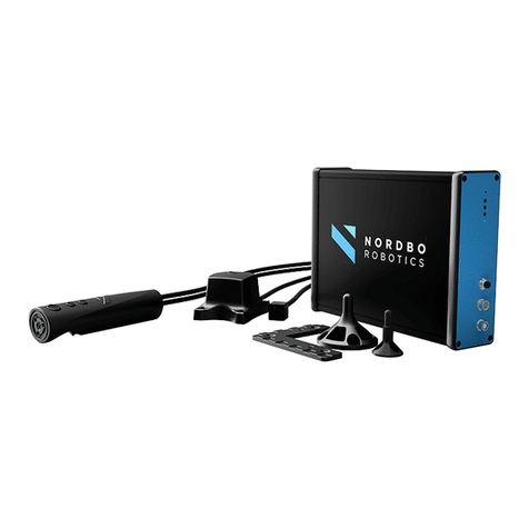
Nordbo Robotics NAC-S20-15 User manual

1 of 44
NAC-S20-15 Active Compensation Unit - User Manual – Ver. 1.0
Copyright
Copyright © 2021 Nordbo Robotics. All Rights Reserved. No part of this manual may be reproduced
or transmitted in any form or by any means, electronic or mechanical, including photocopying and
recording, for any purpose without the written permission of Nordbo Robotics.
Disclaimer
The information provided in this documentation contains general descriptions of the use, of one or
more of Nordbo Robotics’ products. Following this document's instruction for installation and use
must not be considered a substitute for making a risk assessment and testing the specific application
and setup. Neither Nordbo Robotics nor any of our affiliates or subsidiaries shall be held responsible
for the consequences that arise from misuse of – or misunderstanding of – any information stated in
this document.
If any instructions are considered unclear it is the user’s responsibility to contact Nordbo Robotics
for clarification of the issue(s) before making use of said unclear instructions.
If the user has any suggestions for improvements, amendments, or if errors have been found in this
release, please notify Nordbo Robotics.
Nordbo Robotics reserves the right to make refinements or changes without notice.
Warranty
Warranty void if products are opened. The warranty further excludes failure resulting from improper
use or installation, normal wear and tear, abuse, accidents, neglect, fire, water, lightning, or other acts
of nature, causes external to the product, or other factors beyond Nordbo’s control.
Contact
Nordbo Robotics A/S
Noatunvej 2
5000 Odense, Denmark
Phone: +45 81 81 98 81
Mail: info@nordbo-robotics.com

2 of 44
NAC-S20-15 Active Compensation Unit - User Manual – Ver. 1.0
Table of Contents
1. Introduction 4
1.1. Intended Use 4
1.2. Prerequisites 4
1.3. Safety Warnings 4
2. Product information 5
2.1. Included in the Package 6
2.2. Technical Specifications 7
2.3. Mechanical Dimensions 8
2.4. NAC-S20-15 Overview 9
2.5. NAC-CTRL Interfaces 10
3. Web Interface & Configuration 12
3.1. Overview of Web Interface 13
3.2. How to Access the Web Interface 14
4. Configuring the NAC Using Web Interface 18
4.1. Enable/Disable Digital IO Interface Control 18
4.2. Configure Force Registers 19
4.3. Configure “Is moving” 20
4.4. Configuring Static IP 21
4.5. Configure DHCP Client 22
4.6. Updating the Firmware 23
5. Installing the NAC-S20-15 25
5.1. Connection Scheme, robots 26
5.2. Connection Scheme, PLC/IPC 27
5.3. Pneumatic Installation 28
5.4. Electrical Installation 29
6. Controller Functions 32
6.1. Idle 32
6.2. Active Force Control 32
6.3. Retract 33
6.4. Load Calibration 33

3 of 44
NAC-S20-15 Active Compensation Unit - User Manual – Ver. 1.0
7. Control via Digital IO Interface 34
7.1. Logic Status of Input and Outputs 34
7.2. Determine Unit is Ready 34
7.3. Active Force Control 35
7.4. Initiate Calibration 35
7.5. Monitor NAC-S20-15 Motion and Error 36
8. Control via Ethernet TCP/IP Interface 37
9. Troubleshooting 41
9.1. Unable to Connect to the Controller 41
9.2. Reset Controller to Factory Defaults 42
9.3. Support Requests 42
10. Technical Appendix 43
10.1. Connection Specifications 43

4 of 44
NAC-S20-15 Active Compensation Unit - User Manual – Ver. 1.0
1. Introduction
1.1. Intended Use
This document serves as a guide for the installation of Nordbo Robotics’ Active Compensation unit
(NAC) on a manipulator. This guide does not provide any information about risk assessment which
must be carried out before initiating any robot movements.
1.2. Prerequisites
This documentation is intended for people who have experience in installation, commissioning,
programming, and diagnostics of automation systems. Furthermore, it is expected that the person
using this manual understands the risks related to working with industrial robots. It is recommended
reader should also have basic knowledge in using a computer and configuration of network settings.
1.3. Safety Warnings
Following instructions must be read thoroughly by anyone intending to use this product.
Warning! This symbol indicates that potentially hazardous, dangerous, or
unwanted situations can arise from not following the instructions correctly. If
safety instructions are not followed properly it may result in death, personnel
injury, or equipment damage.
Before attempting to connect the NAC to a robot, it is important to ensure that the robot cannot
move unintentionally. The robot must therefore be powered off before attempting to connect the
equipment to the robot.
Robots must always be powered off before attempting to connect wires to the robot’s controller,
or when connecting cables between any of Nordbo Robotics’ products. Only switch the supply
voltage and pneumatics on when installation is fully complete.
The product may be damaged if dropped on hard surfaces. Be aware that connectors can break if
the user pulls or overtightens the cables. Do not perform any repairs on the product(s). In the event
of a defect: replace the control unit or/and tool unit.
The product can only be used within the specified range. Using the product outside of its specified
range may create unexpected results. Nordbo Robotics is not liable for any damage or injury resulting
from the use of the product.

5 of 44
NAC-S20-15 Active Compensation Unit - User Manual – Ver. 1.0
2. Product information
The Nordbo Active Compensation unit (NAC) is a solution for applications with where a constant,
specifiable force between tool and workpiece is required. The NAC consist of two parts, a tool unit,
and a controller. The force can be specified through the controller using IO or ethernet, and the
integrated sensors ensure that high contact forces are prevented during initial part contact.
Figure 1 – Tool Unit
Figure 2 - Controller
Figure 3

6 of 44
NAC-S20-15 Active Compensation Unit - User Manual – Ver. 1.0
2.1. Included in the Package
Picture
Code
Description
NAC-CTRL
Controller for the NAC-S20-15
controllable by IO or ethernet.
NAC-S20-15
Tool unit with a stroke of 20 mm
and a maximum payload capacity
of 15 kg.
Ethernet cable RJ45
Ethernet cable for connecting the
NAC-CTRL.
NAC Cable
Communication cable to connect
the NAC-CTRL and the NAC-S20-
15.
IO modules
IO modules that can be used directly
with most common robot brands.
Table 1

7 of 44
NAC-S20-15 Active Compensation Unit - User Manual – Ver. 1.0
2.2. Technical Specifications
General specifications
Maximum force (push/pull)
150 N / 110 N
Maximum allowed external moment
16 Nm
Stroke length
20 mm
Control Interface
Ethernet TCP/IP
Digital IO ports
Parameterization Interface
Web interface
Pneumatic specifications
The NAC tool needs to be connected to a supply of compressed air through an air-regulator to
regulate push/pull force
Maximum supply pressure
1.0 MPa
Minimum supply pressure
0.1 MPa1
Nominal supply pressure
0.7 MPa
Maximum flow rate
0.6 L/min
Electrical specifications
Power supply voltage
24VDC ±10%
Power supply current consumption
Typical 0.30A, Up to 2A
Digital IO interface
Switch logic
IO logic voltage ratings
Maximum output current
NPN
5 to 48V
0.22A
Ambient specifications
Operating ambient temperature
0° to +50°
Storage ambient temperature
-10° to +75°
Cooling
Passive
Operating humidity (at 25° C)
0% to 85%, No condensation
Degree of protection
NAC-S20-15: IP67 with full pin and fitting allocation
NAC-CTRL: IP40 with full pin allocations
Table 2
1Maximum possibly actuated force will be reduced when supply pressure is under nominal. At 0.1MPa the maximum
actuated force is 25N

8 of 44
NAC-S20-15 Active Compensation Unit - User Manual – Ver. 1.0
2.3. Mechanical Dimensions
Unit
NAC-S20-15
NAC-CTRL
Weight
2.6 Kg
1.2 Kg
Dimensions
Height
Width
Depth
121-141 mm
110 mm
110 mm
56.26 mm
106.13 mm
226 mm
Mounting Tool Side
Bolts
Flange Diameter
M5-10
Ø60mm
-
Mounting Fixation Site
Bolts
Flange Diameter
M5-10
Ø60mm
-
Table 3
Figure 4
Figure 5
Mounting Fixation Side
Mounting Tool Side

9 of 44
NAC-S20-15 Active Compensation Unit - User Manual – Ver. 1.0
2.4. NAC-S20-15 Overview
Figure 6
ID
Description
Functionality
1
Mounting hole pattern, fixation
site
Used when mounting the tool unit on a stable surface or
on a robot flange.
2
Air, in
Connect tube to supply air to the tool unit.
3
Interface for NAC control Unit
Use the supplied cable to connect the tool unit and the
controller.
4
Air, out
Connect tube for exhaust air
5
Mounting hole pattern, tool
side
Used when mounting a tool on the tool unit.
Table 4
5
1
2
3
4

10 of 44
NAC-S20-15 Active Compensation Unit - User Manual – Ver. 1.0
2.5. NAC-CTRL Interfaces
NAC-CTRL Interface, Front
Figure 7
ID
Description
Functionality
A
Ethernet Connection
For connecting the controller to a PC.
B
Interface to NAC tool unit
For connecting the controller to the NAC.
1
LED status indicator
Ready for operation indicator. Is turned “On” when the
NAC is ready for operation.
2
LED status indicator
Ethernet session indicator. The LED is only turned “On”
when there is a connection using the Ethernet TCP/IP
connection.
3
LED status indicator
System state indicator. The LED is “Off” when the system is
in idle state, “On” when system is in active force control
state. The LED is blinking when an error has occurred, and
the device is in error state.
4
LED status indicator
Power indicator. The LED is “On” when the NAC-CTRL is
powered on.
RES
Reset button
Hold to reset the controller to the default settings.
Table 5
A
B
1
2
3
4
RES

11 of 44
NAC-S20-15 Active Compensation Unit - User Manual – Ver. 1.0
NAC-CTRL Interface, Back
Figure 8
ID
Description
Functionality
C
Power supply input
Use to power the NAC controller.
D
IO interface
Use to connect and control the NAC using inputs/outputs.
Table 6
C
D

12 of 44
NAC-S20-15 Active Compensation Unit - User Manual – Ver. 1.0
3. Web Interface & Configuration
The NAC can be reconfigured by accessing its integrated web interface. The web interface is
accessible by connecting the NAC-CTRL to a PC via ethernet link. Input the NAC-CTRL’s IP address
in a web browser e.g., Internet Explorer or Google Chrome to access the settings.
The integrated web interface of the NAC supports:
•Diagnostics of NAC
•Parameterization target forces selectable when using the IO interfaces
•Updating the NAC-CTRL and NAC-S20-15
•Configuring Network settings for the NAC
Figure 9

13 of 44
NAC-S20-15 Active Compensation Unit - User Manual – Ver. 1.0
3.1. Overview of Web Interface
The NAC web interface contains the tabs listed in the following table.
Figure 10 - NAC web interface
Tab
Functions
Configuration
•
Configuration IO Interface
oEnable disable control using IO interface
oSetting predefined target forces and ramp time for each of the
16 preset registers which can be selected using the 4-bit IO
register indexing
oIs moving parameterization
Timeout of is moving signal. How long the actuator
should stand still before it is considered not moving
Distance threshold of how far the actuator should move
before it is considered being in motion
Network
•Enable/Disable DHCP.
Note: If enabled the NAC will gain an IP address from the networks
DHCP provider
•Static address, subnet mask and default gateway if DHCP is disabled
Update
•Update firmware on NAC control unit and Tool unit
About
•Firmware version number
•Serial number
Table 7: Website tab functions for NAC web interface

14 of 44
NAC-S20-15 Active Compensation Unit - User Manual – Ver. 1.0
3.2. How to Access the Web Interface
Before the controller can be accessed through an internet browser by typing in the IP address of the
controller, the network settings may need to be configured. The following section explains how to
connect to the controller using a Windows 10 PC.
Note: Default settings for the NAC-CTRL is having a static IP address of 192.168.1.100. Adding the
device to a network with an existing device having the same IP address can cause network faults. For
initial commissioning, connect the control unit directly to a PC via the Ethernet interface.
Step 1
Connect the controller's power supply and connect to a PC using an ethernet cable.
Step 2
Open Network & Internet settings by right-clicking on the Wi-Fi/LAN icon in the menu.
Figure 11

15 of 44
NAC-S20-15 Active Compensation Unit - User Manual – Ver. 1.0
Step 3
Click ”Change adapter options”.
Figure 12
Step 4
Right-click on ”Ethernet 3” and select “Properties.”
Note: Ethernet number may vary from system to system
Figure 13

16 of 44
NAC-S20-15 Active Compensation Unit - User Manual – Ver. 1.0
Step 5
Select Internet Protocol Version 4 (TCP/IPv4) and click “Properties”.
Figure 14

17 of 44
NAC-S20-15 Active Compensation Unit - User Manual – Ver. 1.0
Step 6
Set the IP address to 192.168.1.42
Set the Subnet mask to 255.255.255.0
Figure 15
Step 7
Access the real-time view using a browser by typing the IP address 192.168.1.42.
Figure 16

18 of 44
NAC-S20-15 Active Compensation Unit - User Manual – Ver. 1.0
4. Configuring the NAC Using Web Interface
4.1. Enable/Disable Digital IO Interface Control
Step 1
Click the checkbox “Enable IO Interface”
Figure 17
Step 2
Navigate to the bottom of the configuration page and click “Save”.
Step 3
Apply the new settings by rebooting the NAC-CTRL by powering it off and on again.

19 of 44
NAC-S20-15 Active Compensation Unit - User Manual – Ver. 1.0
4.2. Configure Force Registers
Force registers enables the user to control the actuated force the NAC-S20-15 is applying by indexing
to one of the 16 registers using the 4-force register selection digital input pins.
Figure 18
Step 1
Edit each row in the Force register table
•Assign your target force.
oPositive values correspond to a push force.
oNegative values correspond to a pull force.
•Assign a ramp time.
Step 2
Navigate to the bottom of the configuration page and click “save”.
Step 3
Apply the new settings by rebooting the NAC-CTRL by powering it off and then on again
(pull the power supply).
Table of contents
Other Nordbo Robotics Robotics manuals
Popular Robotics manuals by other brands

Generation Robots
Generation Robots Nao Presenter user guide
adept technology
adept technology Cobra s600 user guide
ST Robotics
ST Robotics R12 instructions
Pro's Kit
Pro's Kit GE-634 Assembly & instruction manual

Pro's Kit
Pro's Kit Probbie II Assembly & installation manual

Pro's Kit
Pro's Kit GE-896 Assembly & instruction manual

