EPV EDGE FREE AcousticPro 4K eFinity Series User manual
12282021JA www.epvscreens.com 1
AcousticPro 4K eFinity Series
EDGE FREE®Acoustically Transparent Fixed Frame Screen
USER’S GUIDE –V2
Product Description:
The eFinity Series is a fixed frame projection screen that uses Elite Prime Vision’s (EPV®) EDGE FREE®
technology. The EDGE FREE® design resembles a giant size flat panel TV display. The eFinity includes a
micro-thin aluminum bezel trim to further enhance the frame appearance and absorb minimal projector
overshoot. An LED kit is also included for mood lighting.
The screen material included in the A4K eFinity fixed frame is our Award-winning AcousticPro 4K, which
is a sound transparent, moiré-free front projection material designed for 4K/8K Ultra HD projectors for
environments with controlled lighting.
For optimum projection performance, please refer to the list below for proper maintenance and cleaning.
•When cleaning the AcousticPro 4K material, use a soft-bristle toothbrush with mild soap to remove
any dirt.
•Never rub or apply pressure when cleaning the surface.
•Never attempt to use any solutions, chemicals or abrasive cleaners on the screen’s surface.
•In order to avoid damaging the screen, avoid touching it directly with your fingers, pens/pencils or
any other sharp or abrasive objects.
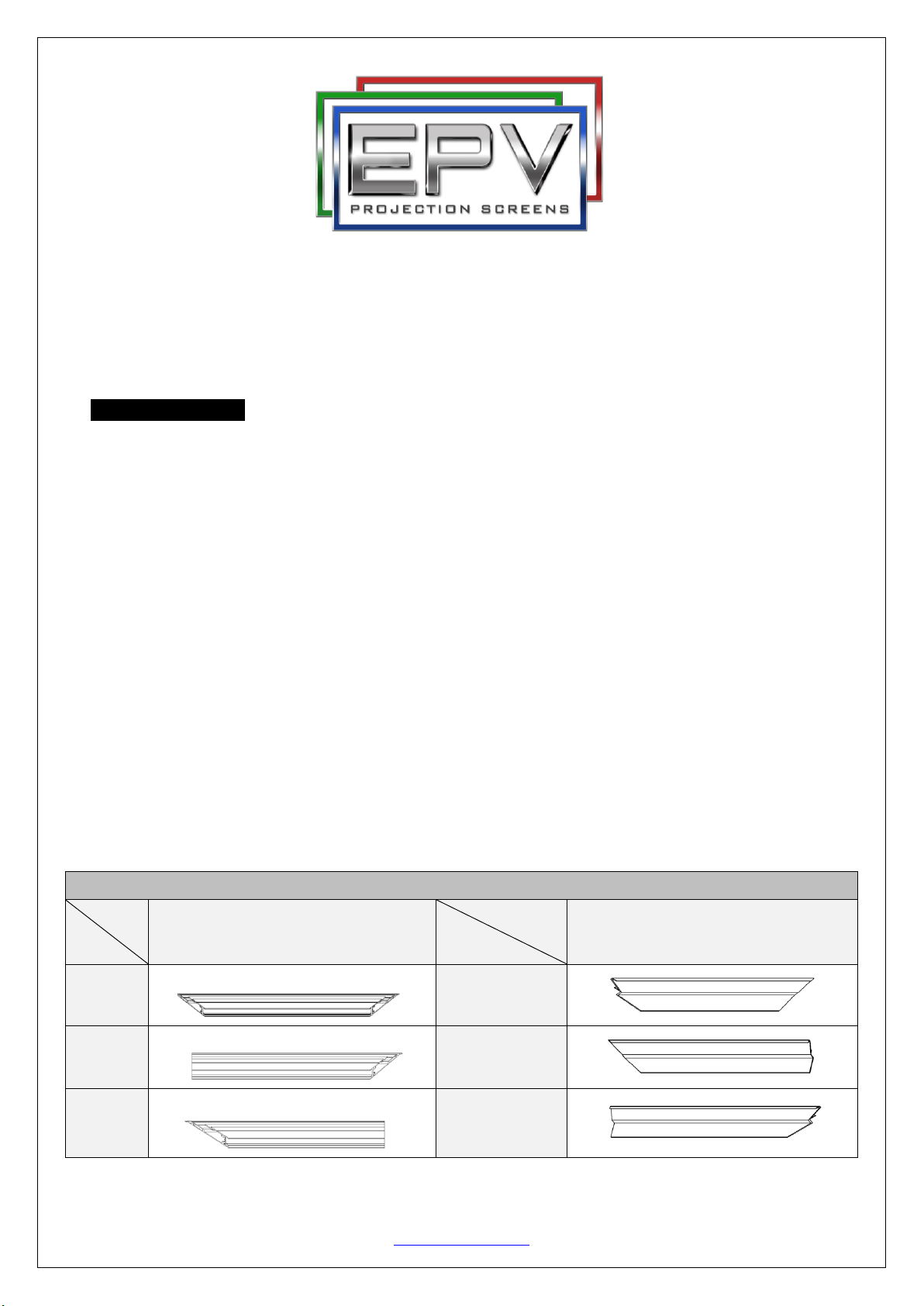
1. Frame and Edge TrimParts List
Qty
item
2 pcs
Main Frame Parts
Qty
item
2 pcs
Edge Trim Parts
Part
A.
vertical frame
Part
D.
Part
B.
½ horizontal frame
Part
E.
Part
C.
½ horizontal frame
Part
F.

12282021JA www.epvscreens.com 2
2. Hardware Parts List
a.
b.
C.
d.
e.
f.
g.
h.
i.
j.
k.
l.
m.
n.
Item
Parts List
EF
100H
EF
110H
EF
120H
EF
135H
EF
150H
a.
Center Joints (1)
4
4
4
4
4
b.
Elbow Joints (2)
8
8
8
8
8
c.
M4x6 Screws
60
60
60
60
60
d.
Spring Hook
2
2
2
2
2
e.
Spring (preloaded)
52
56
64
68
76
f.
Top wall brackets
2
2
2
2
2
g.
M5x50 Wall Screws
6
6
6
6
6
h.
Hollow Wall anchors
6
6
6
6
6
i.
Bottom wall brackets
2
2
2
2
2
j.
Angle cover
4
4
4
4
4
k.
LED light strip clip
24
24
24
24
24
l.
Center Support Bar
1
1
1
1
1
m.
White gloves
2
2
2
2
2
n.
Fiberglass rod
6
6
6
6
6
E.
E
.
F
.
F.
D.
D
.
A
.
A
.
B
.
B
.
C
.
C
.

12282021JA www.epvscreens.com 3
Frame Assembly
Step 1: Place the soft foam sheet on a
clean area on the ground where the
screen will be assembled.
Step 2: Position the pieces of the frame
on the foam sheet in the arrangement
Step 3: Remove the foam in all frame ends before assembling the frame
Step 4: Insert the center joint (a) connectors into one-half of the horizontal frame (b/c) and secure with the
M4x6 screws (c).
Step 5: Connect the elbow joints (b) to the top and bottom sections of the vertical frame. Once inserted,
connect the vertical sections of the horizontal frame sections. Make sure all holes are in alignment and the
frame pieces are flush (no gaps). They should form perfect right angles.
Step 6: Secure the elbow joints by fastening them with M4x6 screws (c), 4 at each corner.
2. Hardware Parts List
a.
b.
c.
d.
e.
f.
g.
h.
i
j.
k.
l.
m.
Remove the foam
Note: Springs are preloaded inside the frame’s grooves.
Please make sure to avoid the springs from falling out
when removing the foam.
Foam sheet
Foam sheet

12282021JA www.epvscreens.com 4
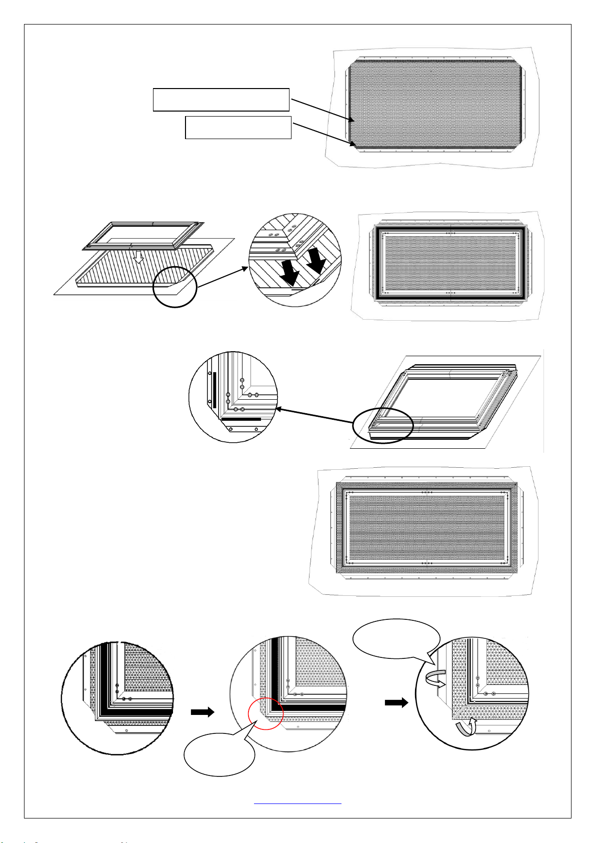
Screen Material
Velcro tape attachment
Step 7: Place the frame on a clean area and use the included velcro tape to adhere it on the back edge of the
frame as show in the illustration below.
Step 8: Put on the white gloves(m) and carefully unroll the screen material on a clean surface from the roller
to the other side as shown below. The back side of the screen material should be placed upwards.
Step 9: Insert the fiberglass rods (n) through the openings. The longer rods are used on the vertical edges of
the screen material, and the shorter rods are used on the horizontal edges, as shown below.
Back side
RFront
Fiberglass rods
Opening
12282021JA www.epvscreens.com 5
Step 10: Next, lay the black backing material on top of
the back side of the AcousticPro 4K material as shown
below. Make sure the black backing’s Velcro is facing up.
Step11: Carefully and gently place the assembled frame on top of the screen material. Make sure to not
allow the angle edge of the frame to come in direct contact with the screen material to avoid puncturing it.
Note: Make sure all the corners of the frame are aligned according to the markings on the back of the
material as indicated below.
Order of items from Top to Bottom:
Frame > Black backing > A4K material > Foam sheet.
Step 12: Make sure the black backing is aligned to edge of the frame, then fold it over to the attach to the
velcro on the frame.
Black backing
Velcro facing up
Fold over
black backing
Align to edge
of the frame

12282021JA www.epvscreens.com 6
Step 13: After attaching the entire black backing to the frame with the velcro, use the spring hook (d) to
attach the spring (e) to the hole located on the screen material’s outer edge in the following order.
Make sure the spring hook goes over the rod.
Attach the four corners first (1).
After those are secure, attach the vertical portions of the material, begin in the center, and move towards the
corners (2). Lastly, attach the horizontal sections of the material by connecting the center of the material
and make your way towards the corners (3).
Note (after all springs have been attached):
Correct material installation –Corners of the screen material are properly wrapped around the corner
edges of the frame and material is evenly tensioned and flat, creating a nicely taut surface.
Incorrect material installation –The corners of the screen material are not properly wrapped along the
edge of the frame leaving the material with unbalanced tension and an uneven finish. To correct, detach
springs from material at the corner(s) where material does not lie flat along the edge of the frame, reposition
the material so that it lies flat and wraps along the edge of the frame, and reattach springs to the material.
Center Support Bar
1
1
1
1
2
3
2
3
To avoid ripples forming in the material it is imperative that all of the corners are properly wrappedaround the
edges as illustrated in the check mark diagrams.
Attach springs to holes
Repeat on all corners
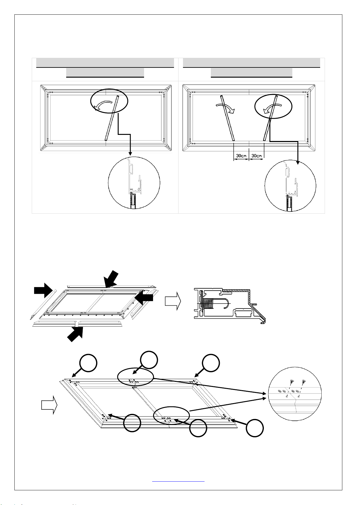
12282021JA www.epvscreens.com 7
Step 14: Insert the Center Support Bar (i)into the upper top groove on the back of the frame with the
bottom end near the approximate center point of the frame and rotate it in at an angle so that both ends of
the bar are in alignment with the groove.
Diagonal Models 150” and below use 1
x Center Support Bar
Diagonal Models above 150” require 2
x Center Support Bars
Attention: Do not proceed with the Edge Trim installation until making sure there are no ripples
in the material.
Edge Trim Installation
Step 15: Place the Edge Trim over each end of the frame and secure with M4x6screws (c).
Start with the center points first, then the rest of the corners as shown below.
1
1
2
2
2
2

12282021JA www.epvscreens.com 8
Step 16: Install the angle cover(j)on each corner of the frame and install the LED light strip to hold down
the angle cover. Then insert the LED light clip (l)to hold the LED light strip in place.
Wall Installation
Step 17: Measure the overall
length and height of the frame and
drill holes for the top brackets.
Line up the wall brackets with the
drilled holes on the installation
location and screw them in using a
Phillips screwdriver. If not
installing into a structural wood
stud, use a hollow wall anchor then
screw in the M5x50 wood screws
with a screwdriver. Make sure the brackets are leveled.
Step 18: Position the fixed frame screen onto the top wall brackets as shown below and push down at the
center of the top of the frame to secure.
Step 19: With the frame slightly tilted outward; connect the bottom brackets onto the bottom groove of the
frame. Then secure them by screwing onto the wall.
For Technical Support or an Elite Prime Vision contact in your area, visit
www.epvscreens.com
Table of contents
Other EPV Projector Accessories manuals


