EPV Polar Star Series User manual

JA12132021 www.epvscreens.com U-00222 1
Polar Star Special Edition Series
Ceiling/Ambient Light Rejecting (CLR®/ALR) Fixed Frame Screen
USER’S GUIDE
V 2.1
Product Description
The Polar Star® Special Edition Series is a fixed frame projection screen from EPV Screens. It has a
hand wrapped velvet covered frame and a tension system for attaching the material for improved flatness.
The screen material included is our award winning ISF Certified Polar Star® which is a front projection
material, precisely formulated forenvironments with minimal control over room lighting. It was designed
to enhance picture brightness, offer accurate color fidelity, and improve contrast levels. The Polar
Star® is best for family rooms, educational facilities, conference rooms, house of worship or any
applications in which incident light is a factor.
In order for the Polar Star® to maintain its projection qualities and optimum performance please refer to the list
below for proper maintenance and cleaning.
•Use a dry microfiber cloth to remove dust from the screen’s surface.
•When cleaning, use a damp microfiber cloth with warm water to remove any marks.
•Never rub or apply pressure when cleaning the surface.
•Never attempt to use any solutions, chemicals or abrasive cleaners on the screen surface.
•In order to avoid damaging the screen, avoid touching it directly with your fingers, pens/pencils or any
other sharp or abrasive objects.

JA12132021 www.epvscreens.com U-00222 2
Frame Parts List
A. Vertical Frame x 2pcs
B. ½ Horizontal Frame x2 pcs
C. ½ Horizontal Frame x 2 pcs
Hardware Parts List
a. M4*4
b. D5*4
c. M4*4
d. D5*4
g.
h.
i.
j.
k.
l.
o.
p.
r.
Item
Parts List
92”
100”
110”
120”
135”
150”
a.
Center Joints- M4 (bottom position)
2
2
2
2
2
2
b.
Center Joints-D5 (top position)
2
2
2
2
2
2
c.
Elbow Joints M4 (bottom position)
4
4
4
4
4
4
d.
Elbow Joints D5 (top position)
4
4
4
4
4
4
g.
M4x7 Screws
24
24
24
24
24
24
h.
Spring
56
60
66
72
80
88
i.
Pull Hook
2
2
2
2
2
2
j.
Wall brackets
4
4
4
4
4
4
k.
Wall Screws M5x50
8
8
8
8
8
8
l.
Hollow Wall anchors
8
8
8
8
8
8
o.
Center Support Bar
1
1
1
1
1
1
p.
White gloves
2
2
2
2
2
2
r.
Φ3 mm Long Iron (sides) rod /
Short rod (top/bottom)
2/4
2/4
2/4
2/4
2/4
2/4
8.
C+B
B+C
A
A
Red
Black
JA12132021 www.epvscreens.com U-00222 3
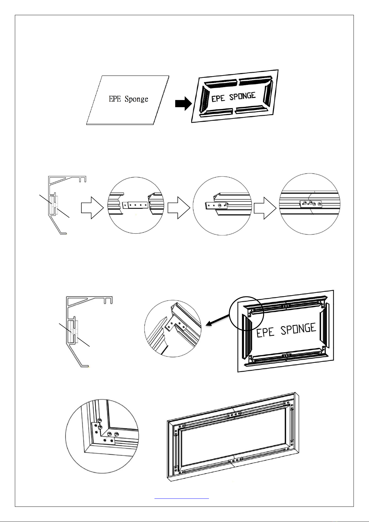
Frame Assembly
Step 1: Place the EPE sponge (foam) sheet on the ground of the area where the screen will be assembled.
Step 2: Position the pieces of the frame on the EPE sponge in the arrangement shown below.
Step 3: Insert center joint (a/b) connectors into one-half of the horizontal frame (B/C) and secure with the
M4x7 screws (g) as shown in the illustration below.
Tip: The center joint (b) with the larger diameter holes should be on top.
Step 4: Connect the elbow joints (c/d) to the top and bottom sections of the vertical frame. Once inserted,
connect the vertical sections to the horizontal frame sections. Make sure all holes are in alignment and the frame
pieces are flush (no gaps). They should form perfect right angles.
Tip: The elbow joint (d)with the larger diameter holes should be on top.
Step 5. Secure the elbow joints by fastening them with M4x7 screws
(g), 4 at each corner.
a.
b.
d.
c.

JA12132021 www.epvscreens.com U-00222 4
c
c
c
c
c
c
c
c
c
c
Screen Material
Step 6: Put on the white gloves (p) and carefully unroll the screen material on a clean surface from the roller to the
other side as shown below. The back
side of the screen material should be
placed upwards. Then place a bottom
grommet (r) on the screen material’s
eyelet and snap in the top grommet (s)
as shown below.
Repeat the process for all eyelets.
Step7: Carefully place the screen on top of the assembled frame as shown below.Make sure that the angular
edges of the frame are not allowed to come into direct contact with the screen material to avoid puncturing.
Step 8: Insert the rods (r) through the sleeves according to their corresponding lengths on each edge of the
screen as shown below. The short rods (top/bottom) will overlap to secure a firm grasp in the middle areas.
Front
Back Side
r. (Red tips)
Back Side
r. (Black tips)
Back Side
Back
Side
Go through the hole
from bottom to top

JA12132021 www.epvscreens.com U-00222 5
How to attach the springs
Step 9: Hook one end of the spring and secure inside the groove of the frame, use the spring hook (i)to attach
the spring to the hole located on the screen material’s outer edge in the following order.
First connect on four corners, steps 1-4. make sure all four corners are fixed before proceeding with next spring.
Continue to attach the remaining springs to the material in steps 5-12 in the follow order.
h.
i.
Spring must hook both
overlapping
short rods.
c
c
1
2
4
3
5
6
7
8
9
10
11
12

JA12132021 www.epvscreens.com U-00222 6
Step 10: Insert the Center Support Bar (o) into the upper top groove on the back of the frame with the bottom end
near the approximate center point of the frame and rotate it in at an angle so that both ends of the bar are in
alignment with the groove.
Notice to Installer:
Please use the following installation instructions to obtain superior optical performance from the Polar
Star Angular Reflective ALR (Ambient Light Rejecting) Screen
Make sure to follow these instructions in order for the CineGrey3D/ 5D to perform correctly.
1. Ambient Light must not come from the same direction as the projector’s light
2. Not compatible with Ultra/Short-Throw Projectors
Projector Ceiling Installation: Make sure the projector (light in) is angled (ϴ1) to reflect (ϴ2) at the mirror-
opposite angle (light out) to align with the viewer’s eye level.
Diagonal Models 150” and
below use 1 x Center Support
Bar
Diagonal Models above 150”
require 2 x Center Support Bars
Place a center support
bar 30 cm (11.8”) apart
from the center (red
line).

JA12132021 www.epvscreens.com U-00222 7
Projector Tabletop: Make sure the projector (light in) is angled (ϴ1) to reflect (ϴ2) at the mirror-opposite
angle (light out) to align with the viewer’s eye level.
Images are not up to scale and are for illustrations purposes only.
Note: Improper installation will result in light loss and produce a dark image. This is due to the projector’s light
reflecting in the wrong direction.
Installation
Step 11: Measure the overall length and height of the frame and drill holes for the top brackets. Line up the wall
brackets with the drilled holes on the installation location and screw them in using a Phillips screwdriver. If not
installing into a structural wood stud, use a hollow wall anchor then screw in the M5x50 wood screws with a
screwdriver. Make sure the brackets are leveled.
Model/Size
X = Wall bracket distance
X1 = Bracket hole distance
Y = Top/Bottom Wall Bracket Height
92”
1100mm (43.30”)
30mm (1.18”)
1180mm (46.46”)
100”
1170mm (46.06”)
30mm (1.18”)
1280mm (50.39”)
110”
1280mm (50.39”)
30mm (1.18”)
1410mm (55.51”)
120”
1390mm (54.72”)
30mm (1.18”)
1530mm (60.24”)
135”
1550mm (61.02”)
30mm (1.18”)
1720mm (67.72”)
150”
1720mm (67.72”)
30mm (1.18”)
1900mm (74.80”)
Don’t lock the screw for
bottom brackets to allow the
screen to move up/down.
j.
k.
Diagonal Sizes of 150” and below use 4 x wall brackets

Table of contents
Other EPV Projector Accessories manuals

EPV
EPV Peregrine HD 2 series User manual

EPV
EPV Twilight Manual User manual

EPV
EPV Polar Max Recessed Series User manual

EPV
EPV EDGE FREE Sonic AT8 ISF eFinity Series User manual

EPV
EPV Twilight Portable Series User manual

EPV
EPV DarkStar Max UST Series User manual

EPV
EPV EDGE FREE AcousticPro 4K eFinity Series User manual


