EPV DarkStar Max UST Series User manual
02142023JA 1 www.epvscreens.com
DarkStar®Max UST Series
Ceiling Ambient Light Rejecting Electric Wall/Ceiling
Projector Screen
(For tabletop ultra-short throw projectors)
User’s Guide –E/H Type (RC1)
V1
Visit www.epvscreens.com for the latest updated version
Important Safety & Warning Precautions
Make sure to read this user’s guide and follow the procedures below.
Caution: The screen’s Black Top Drop is already set to its maximum drop limit. There is NO extra black-matte drop
material on the roller. Please be aware that altering the vertical limit switch to drop the screen material off the roller
voids your warranty with EPV Screens. Unapproved changes or modifications (except for cutting the power cord for
hardwire installations) to this unit are prohibited and will likewise void your warranty.
•Please retain this user’s guide for future reference.
•To avoid damaging the unit, do not use with any unauthorized accessories not recommended by the
manufacturer.
•Handle the unit carefully during transportation to avoid any damages.
•To ensure safe and reliable operation, make sure the power connection is secure.
•The power source should be close to the unit and easily accessible.
•Do not install the unit on uneven, or inclined surfaces.
•To avoid electrical shock or product damage, do not install this device in a damp place.
•Do not place any heavy objects over the power cord.
•Position the power cord properly to avoid creating a trip hazard.
•Avoid electrical shock or fire, by not overloading the power cord.
•The internal & external parts of this unit are not end user serviceable. Do not attempt to disassemble this unit
by yourself. Consult an authorized technician instead.
•Make sure the power source that this unit is connected to has a continuous power flow.
•If there is need to use an extension cord, make sure said cord has a compatible power rating.
•Do not handle this or any other electrical device if you are wet or standing in water.
•Whenever the screen reaches its end of life, follow local environmental guidelines regarding its proper
disposal.
Do not use this unit under the following circumstances.
•Disconnect the power cord if exposed to moisture, rain, wind, electrical storms or snow.
•Avoid exposure to direct sunlight or any of the conditions stated in the previous bullet point.
•Keep away from fire or other high temperature heat sources.
•Cut off the power supply first before attempting maintenance or removal.
•Do not attempt to use this screen if there are obvious signs of damage.
•To avoid possible injury and/or an electric shock, do not attempt to use the screen if there is obvious damage
or if there are any evident broken parts.

02142023JA 2 www.epvscreens.com
NOTE: This equipment has been tested and found to comply with the limits for a Class B digital device, pursuant to
Part 15 of the FCC Rules. The product settings are designed to provide reasonable protection against any radio
interference within a residential installation.
Although radio interference affecting other household electronics is unlikely, the following steps can be taken should
RF interference occur.
✓Reorient or relocate the receiving antenna on the device that may be casing the interference.
✓Increase the distance between the screen and the interfering device’s receiver.
✓Connect the projection screen to another power source apart from the interfering device.
SCREEN MAINTAINANCE
Dust, dirt and scratches on the projection screen surface will affect the quality and performance of the projection
image. For optimal results we advise to pay attention to the following instructions.
1. The screen surface has a horizontal linear structure. DO NOT wipe the screen up and down or in a circular motion.
Wipe gently from left to right only.
2. Clean the dust on the screen surface with a soft brush or microfiber cloth. A rough/coarse towel or cloth may
damage the screen’s surface.
3. Gently wipe the screen with a lightly moistened white lint free cloth with water or with a neutral detergent
(1mL/0.33 oz) mixed with water (1000 mL/33.8 oz).
Notes: The following precautions should be followed to avoid damaging the material, which is not
covered under warranty.
•Don’t touch the screen material to avoid leaving oil from your fingerprints.
•Use gloves when handling the material.
•Don’t scratch the material, as it will leave permanent markings on the screen’s surface.
•Don’t point to the screen material with a fingertip or other sharp objects to prevent damage to the material.
•Don’t use acetone, benzene, alcohol and any other organic solvents to clean the screen material. Using such
chemicals will permanently damage the screen.
Pre-Installation
1. Carefully unpack the screen.
2. Always handle the screen upright on a clean, level surface.
3. Keep the screen out of contact with foreign particles such as dust, sawdust, and/or liquids.
4. Make sure to remove the shipping brackets before operating screen to avoid permanent damage.
5. Do not use this product in an outdoor environment. Avoid areas with wind blowing directly on the screen
as this can distort the projection image.
SHIPPING BRACKETS REMOVAL
WARNING!
PLEASE READ BEFORE INSTALLING!
Please note: Before fully
operating the screen. Remove the
shipping brackets from the weight
bar by loosening the 6 screws.
02142023JA 3 www.epvscreens.com
NOTE: Regardless of the mounting method, each screen should be securely installed so that vibrations or pulling
on the viewing surface will not cause the casing to become loose or fall. Included are complimentary mounting
screws that may or may not be appropriate for the installation you are attempting. Always use the correct anchors
to safely secure the screen. This product is for professional integrators only.
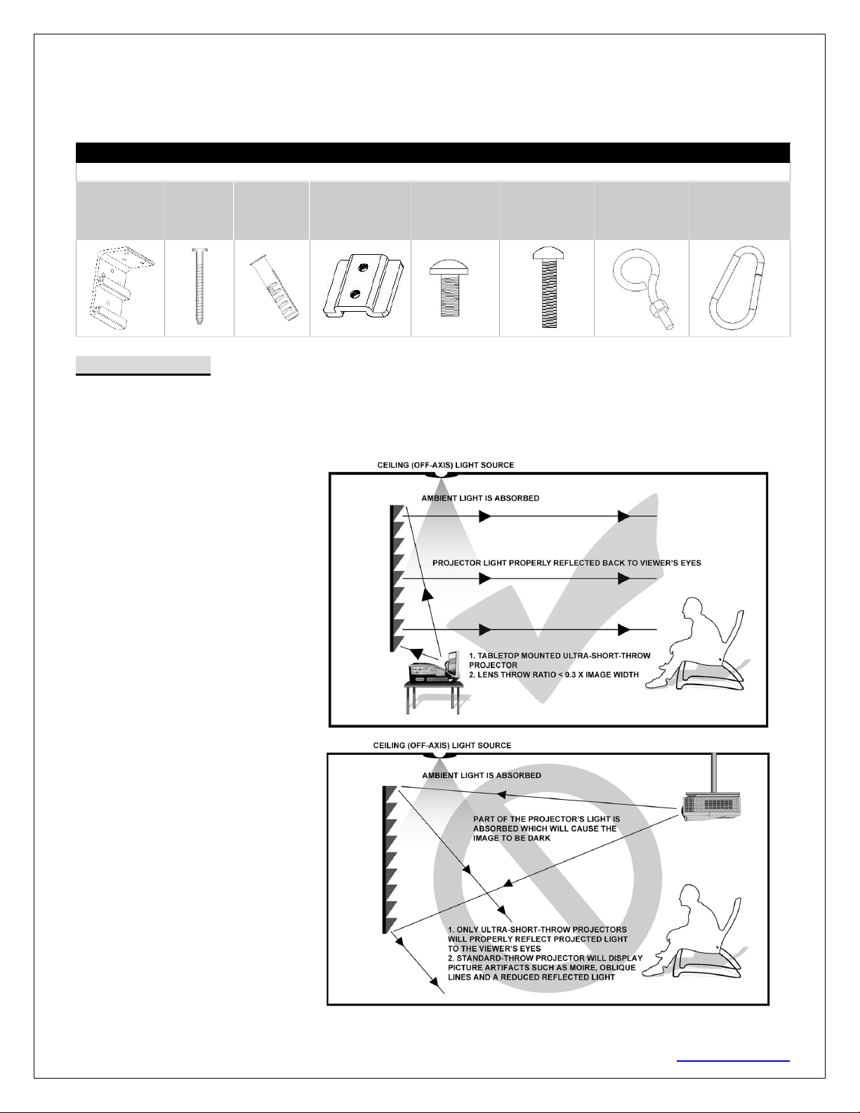
Hardware Parts List
Please make sure all parts listed below are included before proceeding with the installation.
A.
Wall/Ceiling
mount bracket
x2
B. M5x60
Screw x6
C. M12
Dry-wall
anchor x6
D. Bracket
connector x2
(Installed on the
housing)
E. M5x11
Bolt Screw x4
(Attached to
Part D)
F. M5x25MM
round head
cross screws x2
G. M5x30MM
eyebolt screw
& M5 nut x2
H. Carabiner x 2
Notice to Installer:
Proper Projector Placement for DarkStar® UST
The DarkStar® UST is exclusively for table-mounted ultra-short throw projectors as illustrated in example 1 below.
Overhead placement or a standard projector will make the image very dark, on account of the screen’s absorbent
layer deflecting light that is not aligned with its reflective angle.
Example 1: Proper Projector
Installation (Tabletop)
Example 2: Improper Projector
Installation(Ceiling Mounted)
Images are not up to scale and are
for illustrations purposes only.
02142023JA 4 www.epvscreens.com
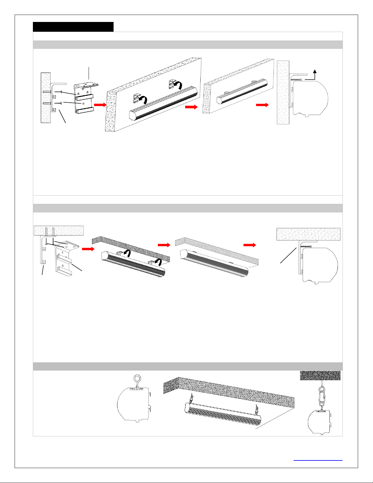
Installation Instructions
A. Wall Mount
Flush hidden mount (movable position)
This mount method allows the screen to slide horizontally.
1. Determine where the screen will be installed. Then, measure and mark the distance between the top and
bottom screw holes from each Wall/Ceiling mount bracket (A).
2. Drill a hole on all marked points and install the brackets with the dry-wall anchor(C), M5x60 screw (B),
Make sure both brackets are properly leveled.
3. Hang the screen by placing the lower “catch” located on the back over the brackets upper “catch”.
4. After making sure the screen is secured, you can slide it left / right to properly center it in position.
5. Lastly, screw the M5 screw (F) into the upper hole of the bracket to add additional support for the screen.
Two or more people are required while one holds the screen in place.
B. Ceiling Mount
I. Ceiling Mount (movable position)
This mount method allows the screen to slide horizontally.
1. Determine where the screen will be installed. Then, measure and mark the distance between the top and
bottom screw holes from each Wall/Ceiling mount bracket (A).
2. Drill a hole on all marked areas and install the brackets with the dry-wall anchor(C), M5x60 screw (B),
Make sure both brackets are properly leveled.
3. Hang the screen by placing the lower “catch” located on the back over the bracket’s upper “catch”.
4. After making sure the screen is secured, you can slide it left / right to properly center it in position.
5. Lastly, screw the M5 screw (F) into the upper hole of the bracket to add additional support for the screen
Two or more people are required while one holds the screen in place.
II. Suspended
1. Screw the eyebolt (G) on
the bracket connector (D).
2. Attach the snap link (H)
through the eyebolt (G) and
connect it to an eyebolt
screw (not included) rated
for the screen’s weight.
Front view
of bracket
(A)
Side view of
bracket (A)
M5x25MM
round head
cross screws (F)
Ceiling
Front view of bracket (A)
Side view of bracket (A)
Wall
M5x25MM round
head cross screws
(F)
Ceiling
02142023JA 5 www.epvscreens.com
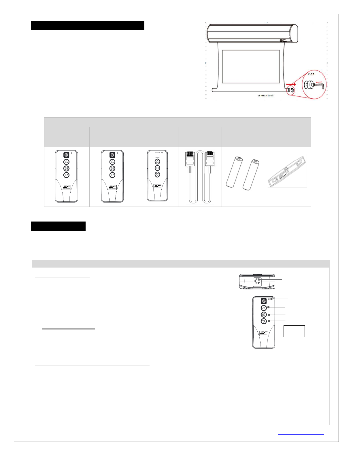
Screen material tension adjustment
(4mm Allen Wrench required and not included)
Remove the weight bar end cap to expose the adjustment tension
knob. This knob has a 4mm Allen port. Insert your 4mm Allen
Wrench and push in the adjustment tension knob, turn clockwise
and your screen will gain more tension. Turn the Allen Wrench
counterclockwise and the screen will lose tension. Please note this
adjustment is not necessary as the tension of the screen has been
pre-set to its factory drop setting. If you would like to adjust the
screen tension, please contact EPV Screens for assistance to avoid
damaging the screen and voiding your warranty.
Dark Star Max UST | Controls and Accessories
A. IR Remote
ZRC1-IR
B. RF Remote
ZRC1-RF
C. Wall box
controller
ZRC1-WB
D. RJ50 cable
ZRC1-RJ50
G. AAA
batteries
H. Bubble
leveler
Screen operation
Electric Current: 110v.
1. After ensuring the power outlet & screen are compatible (voltage), plug the power cord into the power outlet.
2. Once the screen has power, you’ll be able to control it using any of the 5 methods described below.
5 Ways to control the screen
1. IR Remote control (Item A, Fig 1): The Infrared functions by direct line of
sight contact using an effective beam range of 25 feet within a 30-degree angle.
Aim the IR remote directly at either the IR receiver on the Wall Box Controller
or on the screen to operate the screen.
Note: Assure there is no obstruction between the IR remote and IR receiver.
2. RF Remote Control (Item B): The radio waves eliminate the need for a
direct line of sight and has a longer distance control range.
The RF remote is already pre-synced/paired and ready to use. If synchronization/
pairing is needed, please follow the steps below.
How to synchronize/pair a new RF remote:
•Press & hold the “Programming Key”, then press the “Up Key” on the Wall box controller (wall-box
LED flashes). Reference the wall box controller section for programming key location.
•Then press the “Up Key” on the RF remote.
•The Wall box LED will flash 5 times, to indicate the RF remote has been properly synchronized/paired.
LED light
UP
STOP
DOWN
Fig.1
IR/RF remote
IR Lens
(IR remote only)
02142023JA 6 www.epvscreens.com
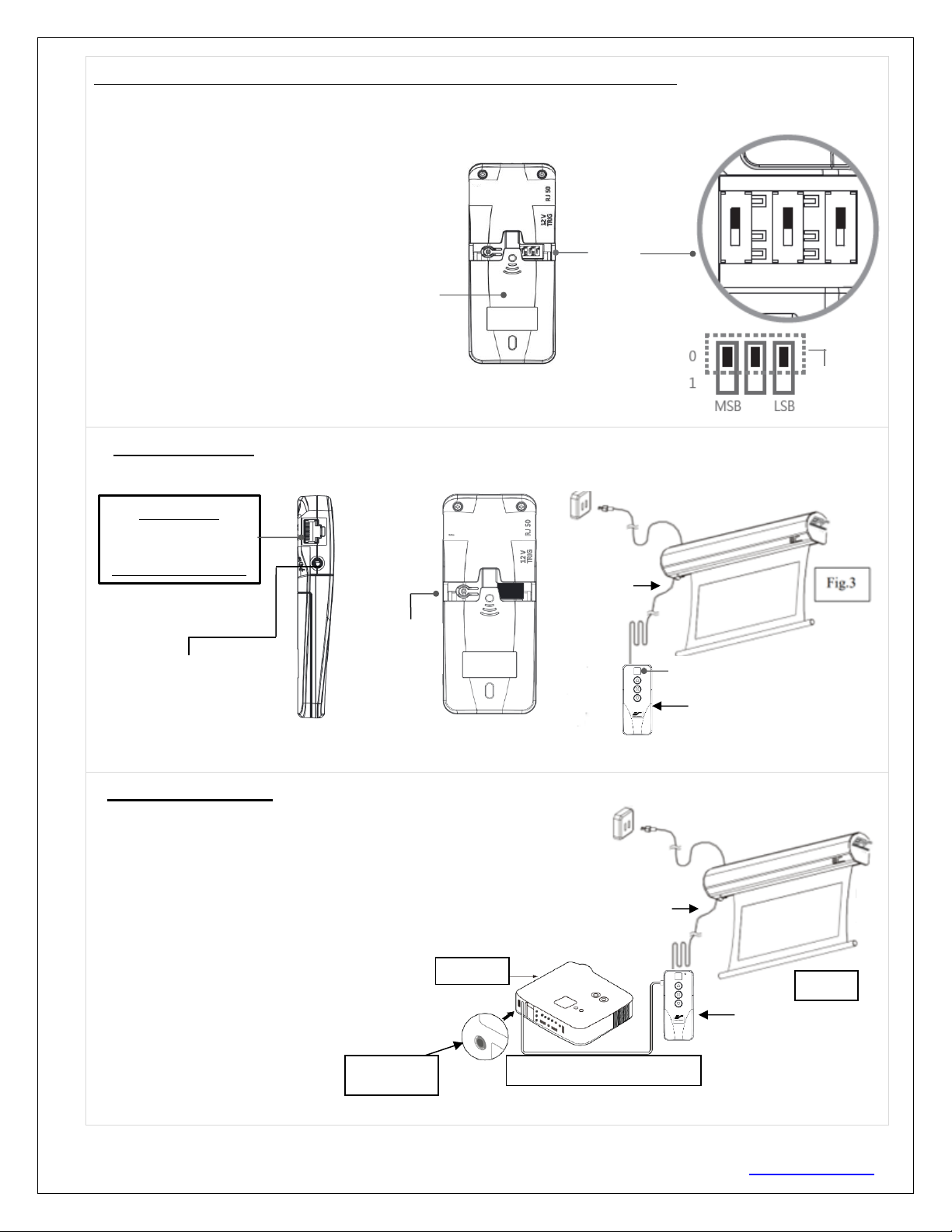
How to change the RF code (For use when multiple screens/RF remotes are owned)
Changing the RF code avoids controlling multiple screens at the same time and prevents electrical interference
leading to accidental control of the screen.
1. Remove the batteries
2. Change the RF code switch
3. Insert the batteries
4. Synchronize it with the wall box controller
3. Wall box controller (Item C, Fig 3): The wall box controller switch is a wall mounted control box with an
up/stop/down button. It plugs directly into the screen’s RJ50 port.
4.Wired 5-12 volt trigger: Requires a 3.5mm to 3.5mm mono cable (not included)
Step 1: Connect one end the RJ50 cable to the screen and the other end
to the Wall box controller.
Step 2: Then connect one end the 3.5mm mono cable to the wall box
controller and the other to the projector.
Once the two cables have been connected, the wired trigger feature is
ready to synchronize the screen’s up/down operation with the
projector’s power cycle.
•Projector on, screen drops
•Projector off, screen raises
Wall box controller
IR Receiver
RJ50 cable
Wall box controller
SIDE VIEW
RJ50 PORT:
Connects to the
Screen RJ50 PORT
(RJ50 CABLE ONLY)
3.5mm mono Projector
Trigger Port (if Projector
equipped)
3.5 mm port
DC 5-12V out
3.5mm to 3.5mm mono cable
Wall box controller
Fig. 4
RJ50 cable
Projector
Wall box controller
BACK VIEW
Programming
Key
Battery compartment
Default
“000”
RF Remote
BACK VIEW
Slide
Switches
for RF Code
change
02142023JA 7 www.epvscreens.com
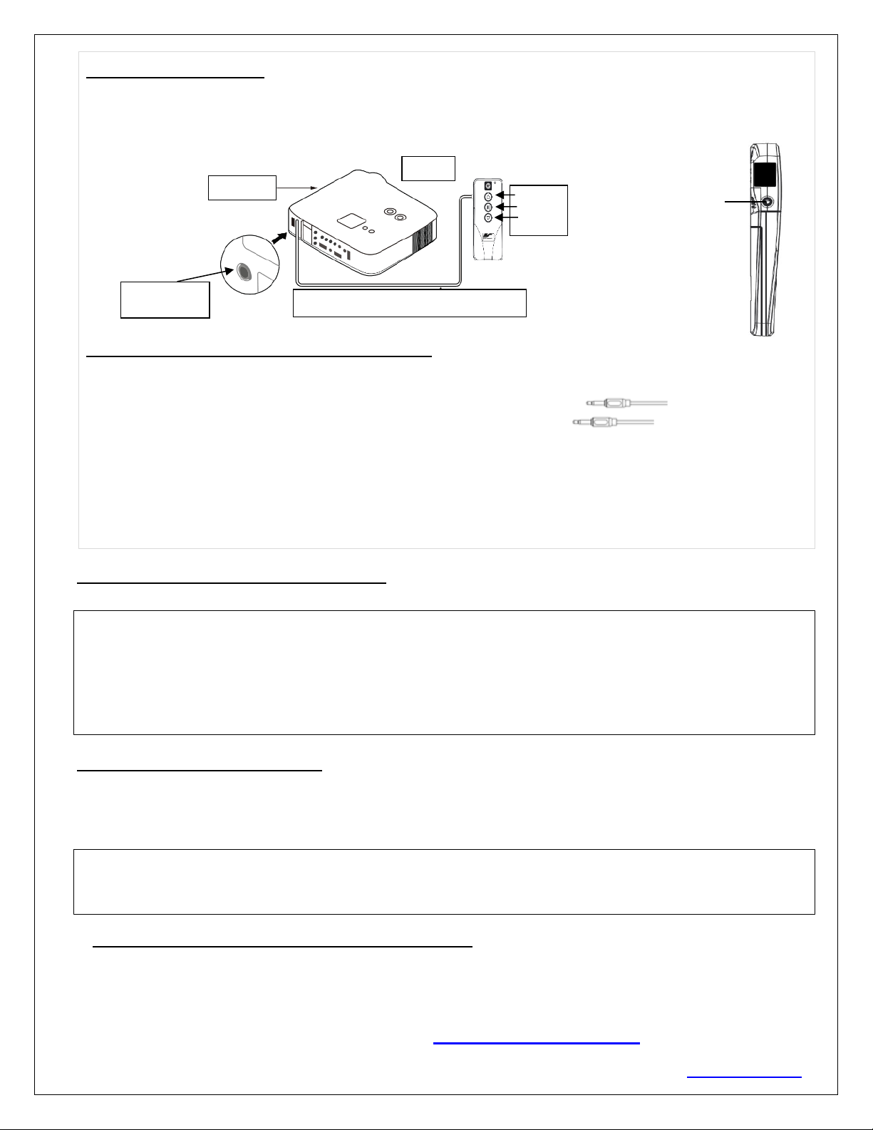
5. Wireless 5-12 volt trigger (Fig 5): Requires a 3.5mm to 3.5mm mono cable (not included).
The Radio Frequency (RF) remote control serves as a dual purpose, independently as a handheld remote control, or
as a Wireless 5-12 volt trigger. The radio frequency technology sends a wireless signal that synchronizes the
screen’s drop & rise with the projector’s power cycle.
Here’s how to set up your Wireless 5-12 volt trigger
The 5-12V wireless trigger should already be synced and ready to work.
Step1: Connect one end of the 3.5 mm mono trigger cable to the RF remote.
Step 2: Connect the other 3.5 mm mono end of the cable to your projector
Step 3: Turn on the projector and the screen should automatically deploy.
Step 4: Turn off your projector and the screen should automatically retract.
(Please be aware, the projector on/off cycle may take longer to fully activate. It usually takes around 20-
30seconds for full off and on cycle each time)
Note: If the wireless trigger feature does not work, please resync the RF remote to the Wall box controller per the
instructions in the Radio Frequency remote section.
ADVANCED Programming Key Instructions: (FOR ADVANCED USERS ONLY)
Wall box controller must be connected to the screen.
1. Preset the Screen’s Drop Position:
Use the RF/IR remote or Wall Box Controller to Drop the screen to the desired position you want to set it at.
Press & hold the “Programming Key”, then press the “Down key” on the Wall Box Controller. The LED will
flash 5 times to confirm new programmed drop position.
2. Clear/Reset the Screen’s Drop Position to factory default:
Press & hold the “Programming Key + “Stop key” on the wall box controller.
For more information, technical support or your local EPV Screens
contact, please visit www.epvscreens.com
Fig 5
3.5 mm port
DC 5-12V out
3.5mm to 3.5mm mono cable
UP
STOP
DOWN
Projector
Mono 3.5mm
Projector
Trigger Port
RF remote control
SIDE VIEW
PROGAMMING NOTE:
The programmed vertical drop position will have +/- 2" tolerance, which will depend on the temperature of the
installed screen environment.
ATTENTION: Reducing the factory’s full screen drop may produce waves/wrinkles on the projection surface
on tab-tension screens. The full drop is recommended to allow the screen to rely on the tab-tension system to
maintain the projection surface flat and taut on all sides.
The same applies on non-tensioned screens, although some level of waves may be present due to the nature
of the screen not being tensioned. If wrinkles/waves develop after making the adjustment to the desired drop
position, reset it to the factory’s default position per the instructions below.
This manual suits for next models
1
Table of contents
Other EPV Projector Accessories manuals

EPV
EPV Polar Star Series User manual

EPV
EPV EDGE FREE AcousticPro 4K eFinity Series User manual

EPV
EPV EDGE FREE Sonic AT8 ISF eFinity Series User manual

EPV
EPV Twilight Portable Series User manual

EPV
EPV Twilight Manual User manual

EPV
EPV Polar Max Recessed Series User manual

EPV
EPV Peregrine HD 2 series User manual
Popular Projector Accessories manuals by other brands


Mitsubishi Electric
Mitsubishi Electric 236CB Features

Burkhardt Leitner
Burkhardt Leitner constructiv telvis II Planning documents

peerless-AV
peerless-AV PRG-1 Installation and assembly manual

Crestron
Crestron AM-200 product manual

Crestron
Crestron IntelliClass IC-300-CSP-P quick start guide

Optoma
Optoma 3D-XL Specifications


