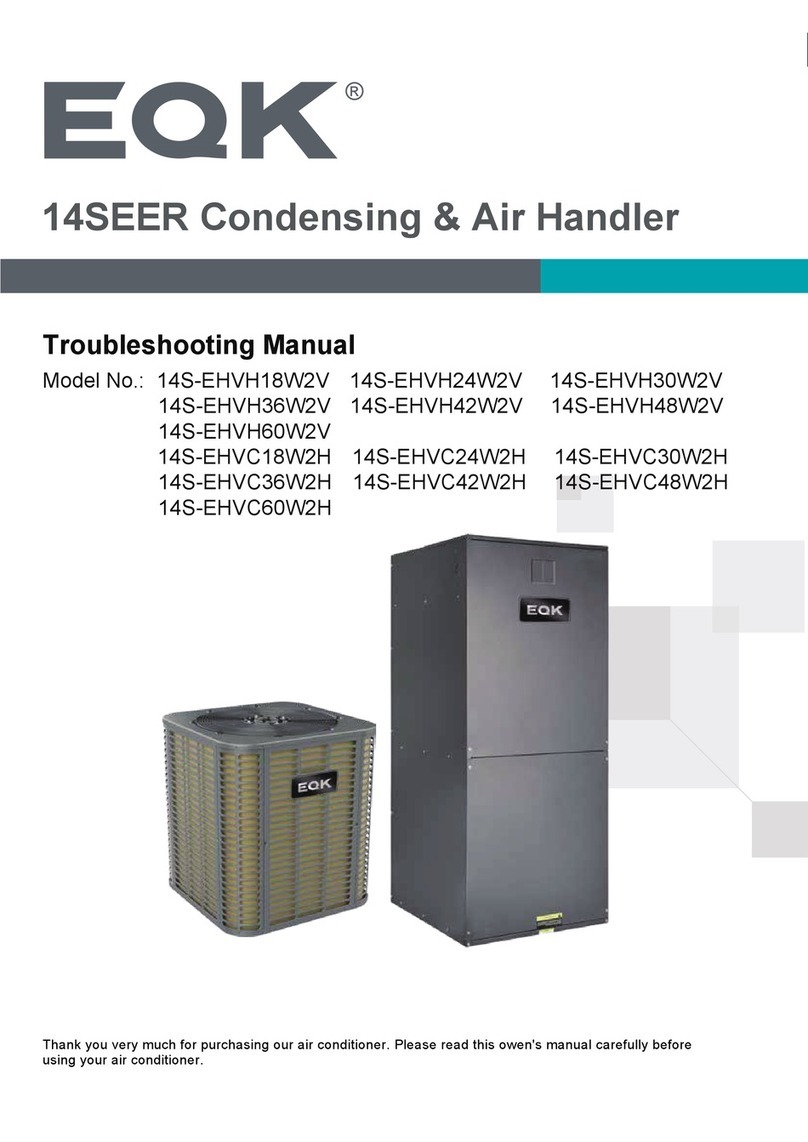
EQK 14S-EHVC18W2V User manual

Thank you very much for purchasing our air conditioner. Please read this owen's manual carefully before
using your air conditioner.
User Manual
14 SEER Condensing Units
Model No.: 14S-EHVC18W2V 14S-EHVC24W2V 14S-EHVC24W2VS
14S-EHVC30W2V 14S-EHVC30W2VS 14S-EHVC36W2V
14S-EHVC42W2V 14S-EHVC48W2V 14S-EHVC60W2V
14S-EHVH18W2V 14S-EHVH24W2V 14S-EHVH30W2V
14S-EHVH36W2V 14S-EHVH42W2V 14S-EHVH48W2V
14S-EHVH60W2V

THANK YOU
Congratulations on your purchase and welcome to the Family.
Your new Air Conditioner combines high-efficiency operation with portable convenience.
By following the operating and care instructions in this manual, your air conditioner will
provide you with many years of reliable service.
Please visit our website
www.eqkhvac.com
For any questions or Technical Support,
Dimensions
Service Space
Piping Diagrams
Wiring Diagrams
Electric Characteristics
Operation Limits
3
4
5
7
9
10

2
WARNING
These instructions are intended as an aid to qualified
licensed service personnel for proper installation, adjust-
ment and operation of this unit. Read these instructions
thoroughly before attempting installation or operation.
Failure to follow these instructions may result in improper
installation, adjustment, service or maintenance possibly
resulting in fire, electrical shock, property damage,
personal injury or death.
RECOGNIZE THIS SYMBOL AS AN INDICATION OF IMPORTANT SAFETY INFORMATION
DO NOT DESTROY THIS MANUAL
Please read carefully and keep in asafe place for future reference by aserviceman.
R
Unitary Small AC
210/240
Certification applies only When the complete system
is listed with AHRI.
R
Unitary Small HP
210/240
Certification applies only When the complete system
is listed with AHRI.

3
DIMENSIONS
Unit Model
Dimensions (Inches)Refrigerant Connection Service
Valve Size
"H" in [mm]"W" in [mm]"L" in [mm]Liquid in Vapor in
18K 25[633]21-4/5[554]3/8 3/4
21-4/5[554]3/8 3/4
21-4/5[554]
3/8 3/4
29-1/7[740]3/8 3/4
29-1/7[740]3/8 3/4
29-1/7[740]3/8 7/8
29-1/7[740]3/8 7/8
24K
30K
36K
42K
48K
60K
25[633]
25[633]
25[633]
32-7/8[835]
32-7/8[835]
32-7/8[835]
21-4/5[554]
21-4/5[554]
21-4/5[554]
29-1/7[740]
29-1/7[740]
29-1/7[740]
29-1/7[740]

4
SERVICE SPACE
1-1/8in
4-3/4in
1-1/8in
1-1/8in
1-1/8in

5
PIPING DIAGRAMS
Applicable for 18k, 24k, 30k, 36k cooling only type
INDOOR OUTDOOR
LIQUID SIDE
GAS SIDE
HEAT
EXCHANGE
(EVAPORATOR)
HEAT
EXCHANGE
(CONDENSER)
COMPRESSOR
Throttle device
High pressure
switch
T5 Discharge
temp. sensor
Applicable for 18k, 24k, 30k, 36k cooling & heating type
INDOOR OUTDOOR
LIQUID SIDE
GAS SIDE
HEAT
EXCHANGE
(EVAPORATOR)
HEAT
EXCHANGE
(CONDENSER)
COMPRESSOR
Throttle device
High pressure
switch
T5 Discharge
temp. sensor
T3 condenser
temp. sensor
4-way
valve

6
vapour-liquid
seporator
Applicable for 42k, 48k, 60k cooling & heating type
T3 condenser
temp. sensor
Low pressure
4-way
valve
INDOOR OUTDOOR
LIQUID SIDE
GAS SIDE
HEAT
EXCHANGE
(EVAPORATOR)
HEAT
EXCHANGE
(CONDENSER)
COMPRESSOR
Throttle device
High pressure
switch
T5 Discharge
temp. sensor
INDOOR OUTDOOR
LIQUID SIDE
GAS SIDE
HEAT
EXCHANGE
(EVAPORATOR)HEAT
EXCHANGE
(CONDENSER)
COMPRESSOR
Throttle device
T5 Discharge
temp. sensor
High pressure
switch
Low pressure
switch
Applicable for 42k, 48k, 60k cooling only type

7
WIRING DIAGRAMS
WIRE INFORMATION
COMPONENT
CODE
WIRE COLOR CODE
NOTES
FACTORY
CONNECTION
PROJECT
CONNECTION
PRACTICALITY
EXTERIOR
DASHED
CIRCLE
YE YELLOW
BR BROWN
OR ORANGE
GN GREEN
BL BLUE
BK BLACK
RD RED
GY GREY
PR PURPLE
WH WHITE
CIRCUIT
DIAGRAM
M
FM
COMPRESSOR
FAN
MOTOR
TB TERMINAL
BLOCK
CAPACITOR
C
KM CONTACTOR
FT EXHAUST
SWITCH
C
RS
L2
L1
Y
C
BL RD BK
YE/GN
C1
GY
BK
BL
24VAC TO POWER
A1
BK
C3
BL
BR
FM
M
WH
A2
YE
/
GN
HP HIGH
PRESSURE
SWITCH
1. The units should use the unattached power switch, stated-cross-section
wires and matching-spec. breaker.
2. Use the fuse within the specified scope, it can not replaced by iron
wires or brass wires.
3. The units should install the stated-cross-section earth wire and keep it
grounding unfailingly.
~
KM
BK
BK
BL
BR
BL
BK
4
1
5
6
KA
WH
FT
802032890091
HP
BL RD
YE
/
GN
KM
C
R
S
BL
RD
BK
YE
/
GN
C
A1
BL
M
PL PH
A2
4- WV
OUTDOOR PIPE SENSOR
KM
CN11
/
T3
2
ON
SW1
1
PROT
-
O
1 2 3 4
4
-
WAY
-
ICOMP
-
I
N1
OUT FAN
4- WAY
COMP
L
N
N
N
N
LP
BL
RD
PCB
CIRCUIT DIAGRAM
~
KM
BK
BK
CN14
/
T5
EXHAUST PIPE SENSOR
BK
C
BR BL
FM YE/ GN
HEATER
HE
BR
TRANS
_
IN
TRANS
_
11V
L1
L2
BK
BL
TO POWER
YE
/
GN
C
Y
B
W
BK
WH
TO
INDOOR
YE
CN20
CN21
BL
HP
43
OR
STATE
ON
OFF
Cold
and
heat
Single
cooling
THREE
PHASE
SINGLE
-
PHASE Showing
the
part
chosen
in
the
actual
installation
SWITCH
SETTING
1 2
SWITCH 34
/
/
THREE
PHASE
380V
SINGLE
-
PHASE
220V
WIRE INFORMATION
COMPONENT
CODE
WIRE COLOR CODE
NOTES
FACTORY
CONNECTION
PROJECT
CONNECTION
PRACTICALITY
EXTERIOR
DASHED
CIRCLE
YE YELLOW
BR BROWN
OR ORANGE
GN GREEN
BL BLUE
BK BLACK
RD RED
GY GREY
PR PURPLE
WH WHITE
M
FM
COMPRESSOR
FAN MOTOR
TB TERMINAL BLOCK
CAPACITOR
C
KM CONTACTOR
FT
EXHAUST
SWITCH
HP HIGH PRESSURE SWITCH
1. The units should use the unattached power switch, stated-cross-section
wires and matching-spec. breaker.
2. Use the fuse within the specified scope, it can not replaced by iron
wires or brass wires.
3. The units should install the stated-cross-section earth wire and keep it
grounding unfailingly.
802033290003
Scheme 1:Applicable for 18k, 24k, 30k, 36k, 42k, 48k, 60k cooling only type
Scheme 1:Applicable for 18k, 24k, 30k, 36k, 42k, 48k, 60k cooling & heating type

8
C
R
S
BL
RD BK
YE/GN
C
M
PH PL
4-WV
OUTDOOR PIPE SENSOR
CN11/T3
2
ON
SW1
1
RC
OUT
FAN
4
-
WAY
COMP
L
N
N
N
N
LP
PCB
~
CN14
/
T5
EXHAUST PIPE SENSOR
Y
R
B
W
RD
YE
BL
HP
43
PR
L1
L2
T1
T2
A1 A2
KM
BL
BK
C
BR BL
FM YE/GN
W B Y
BL
L1
L2
C
HEATER
RD
BK
RD
BK
BL
BK
BK
BK
BR
BK
TRANS
_
IN
CN20
TRANS
_
11V
CN21
TO THERMOSTAT
TO POWER
BK
BR
GROUNG
STATE
ON
OFF
Cold
and
heat
Single
cooling
THREE
PHASE
SINGLE
-
PHASE Showing
the
part
chosen
in
the
actual
installation
SWITCH
SETTING
1 2
SWITCH 34
/
/
THREE
PHASE
380V
SINGLE
-
PHASE
220V
WIRE INFORMATION
COMPONENT
CODE
WIRE COLOR CODE
NOTES
FACTORY
CONNECTION
PROJECT
CONNECTION
PRACTICALITY
EXTERIOR
DASHED
CIRCLE
YE YELLOW
BR BROWN
OR ORANGE
GN GREEN
BL BLUE
BK BLACK
RD RED
GY GREY
PR PURPLE
WH WHITE
M
FM
COMPRESSOR
FAN MOTOR
TB TERMINAL BLOCK
CAPACITOR
C
KM CONTACTOR
FT
EXHAUST
SWITCH
HP HIGH PRESSURE SWITCH
1. The units should use the unattached power switch, stated-cross-section
wires and matching-spec. breaker.
2. Use the fuse within the specified scope, it can not replaced by iron
wires or brass wires.
3. The units should install the stated-cross-section earth wire and keep it
grounding unfailingly.
802032490059
WIRE
INFORMATION
COMPONENT CODE
WIRE
COLOR
CODE
NOTES
YE
YELLOW
BR
BROWN
OR
ORANGE
GN
GREEN
BL
BLUE
BK
BLACK
RD
RED
GY
GREY
PR
PURPLE
WH
WHITE
CIRCUIT
DIAGRAM
M
FM
COMPRESSOR
FAN MOTOR
TB TERMINAL BLOCK
CAPACITOR
C
KM CONTACTOR
FT EXHAUST SWITCH
CR
S
BL
RD
BK
YE
/
GN
C
TO THERMOSTAT TO POWER
C
BL
BR
FM
M
YE
/
GN
HP HIGH PRESSURE SWITCH
1. Gounded and all wiring to conform to I.E.C.
2. Replacement wire must be the same gauge and insulation type as original wire.
3. The units should install the stated-cross-section earth wire and keep it
grounding unfailingly.
4.According to the actual connection of low-voltage switch or short wiring.
~
802032490064
BL
BR
BL
BK
L1
L2
T1
T2
A1 A2
FT
HP
RD
BK
BK
YE
KM
L1
L2
BL
BK
BL
BL
BL
C
Y
FACTORY
STANDARD
FIELD
INSTALLED
FACTORY
OPTIONAL
GROUNG
LP
NOTE 4
Scheme 2:Applicable for 18k, 24k, 30k, 36k, 42k, 48k, 60k cooling only type
Scheme 2:Applicable for 18k, 24k, 30k, 36k, 42k, 48k, 60k cooling & heating type

ELECTRIC CHARACTERISTICS
9
Model Power Supply
Hz Phase Voltage
60 1 198V 242V
60 1 198V 242V
60 1 198V 242V
18K
24K
30K
36K
42K
48K
60K
60 1 198V 242V
60 1 198V 242V
60 1 198V 242V
60 1 198V 242V
Min. Max.
220-230V
220-230V
220-230V
220-230V
220-230V
220-230V
220-230V

OPERATION LIMITS
10
Temperature
Mode Cooling operation
Room temperature 63℉~86℉
Outdoor temperature
64℉~109℉
Cooling
Heating operation
63℉~86℉
19℉~75℉
Heating
Outdoor temperature(
℉
DB)
Outdoor temperature(
℉
DB)
indoor temperature(℉ WB)
50 59 68 77 86 95
59
68
77
86
95
104
113
STD
indoor temperature(℉ WB)
50 59 68 77 86 95
23
32
41
50
59
68
77
STD

Installation Procedure
Location Selection
Outdoor Unit Installation (Top Discharge Unit)
Refrigerant Pipe Installation
Vacuum Drying And Leakage Checking
Additional Refrigerant Charge
12
13
14
16
18
19
Engineering Of Insulation
Engineering Of Electrical Wiring
Test Operation
Trouble Code Table
20
21
23
24
11

INSTALLATION PROCEDURE
12
Vacuum drying and leakage checking
Additional refrigerant charge
Insulation the joint part of refrigerant pipe
Wiring connection and electric safety checking
Test operation
Refrigerant pipe
installation and insulation
Drainage pipe installation
and insulation
Indoor unit installation
location selection
Outdoor unit installation
location selection
Indoor unit installation Outdoor unit installation
Refrigerant pipe
installation and insulation
Drainage pipe installation
and insulation

LOCATION SELECTION
13
1.Indoor unit location selection
The place shall easily support the indoor unit’sweight.
The place can ensure the indoor unit installation and inspection.
The place can ensure the indoor unit horizontally installed.
The place shall allow easy water drainage.
The place shall easily connect with the outdoor unit.
The place where air circulation in the room should be good.
There should not be any heat source or steam near the unit.
There should not be any oil gas near the unit
There should not be any corrosive gas near the unit
There should not be any salty air neat the unit
There should not be strongelectromagnetic wave near the unit
There should not be inflammable materials or gas near the unit
There should not be strong voltage vibration.
2.Outdoor unit location selection
The place shall easily support theoutdoor unit’s weight.
Locate the outdoor unit as close to indoor unit as possible
The piping length and height drop can not exceed theallowable value.
The place where the noise, vibration and outlet air do not disturb theneighbors.
There is enough room for installation and maintenance.
The air outlet and the air inlet are not impeded, and not face the strong wind.
It is easy to install the connecting pipesand cables.
There is no danger of fire due to leakage of inflammablegas.
It should be adry and well ventilation place
Thesupport should be flat andhorizontal
Do not install the outdoor unit in a dirty or severely polluted place, so as to avoid blockage of the heat
exchanger in the outdoor unit.
If is built over the unit to prevent direct sunlight, rain exposure, direct strong wend, snow and other scraps
accumulation, make sure that heat radiation from thecondenser is not restricted.

OUTDOOR UNIT INSTALLATION (Top Discharge Unit)
14
1.Location selection
Before starting the installation, select and check the suitability of the location for both the indoor and outdoor
unit. Observe all limitations and clearance requirements. The outdoor unit must have sufficient clearance for
air entrance to the condenser coil, for air discharge and for service access.
Note:For multiple unit installations, units must bespaced aminimum of 18 inches apart. (Coil face to coil
face.)
If the unit is to be installed on ahot sun exposed roof or a black-topped ground area, the unit should be
raised sufficiently above the roof or ground to avoid taking the accumulated layer of hot air into the outdoor
unit.
Provide an adequate structural support.
2.Service space for outdoor unit
3.Install the Unit
On ground installation
The unit may be installed at ground level on asolid base that will not shift or settle, causing strain on the
refrigerant lines and possible leaks. Maintain the clearances shown in Fig.5and install the unit in alevel
position.
1-1/8in
4-3/4in
1-1/8in
1-1/8in
1-1/8in

15
Normal operating sound levels may be objectionable if the unit is placed directly under windows of certain
rooms (bedrooms, study, etc.).
Top of unit discharge area must be unrestricted for at least 6 feet above the unit.
Warning:The outdoor unit should not be installed in an area where mud or ice could cause personal injury.
Elevate the unit sufficiently to prevent any blockage of the air entrances by snow in areas where there will be
snow accumulation. Check the local weather bureau for the expected snow accumulation in your area.
Isolate the unit from rain gutters to avoid any possible wash out of the foundation.
On roof installation
When installing units on a roof, the structure must be capable of supporting the total weight of the unit,
including apadded frame unit, rails, etc., which should be used to minimize the transmission of sound or
vibration into the conditioned space.

REFRIGERANT PIPE INSTALLATION
16
1.Maximum pipe length and height drop
Considering theallowable pipe length and height drop to decide the installation position. Make sure the
distance and height drop between indoor and outdoor unit not exceeded the date in the following table.
Model
Max. Length FT[M]
Max. Elevation FT[M]
≤36,000Btu/h 50[15] 26[8]
>36,000Btu/h
66[20]
33[10]
2.The procedure of connecting pipes
2.1 Choose the pipe size according to the specification table.
2.2 Confirm the cross way of the pipes.
2.3 Measure the necessary pipe length.
2.4 Cut the selected pipe with pipe cutter
Make the section flat and smooth.
90
Lean Crude Burr
o
2.5 Insulate the copper pipe
Before test operation, the joint parts should not be heat insulated.
Max elbow(pcs)
5
5
2.6 Drill holes if the pipes need to pass the wall.
2.7 According to the field condition to bend the pipes so that it can pass the wall smoothly.
2.8 Bind and wrap the wire together with the insulated pipe if necessary.
2.9 Set the wall conduit
2.10 Set the supporter for the pipe.
2.11 Locate the pipe and fix it by supporter
For horizontal refrigerant pipe, the distance between supporters should not be exceed 1m.
For vertical refrigerant pipe, the distance between supporters should not be exceed 1.5m.
2.12 Connect the pipe to indoor unit and outdoor unit by brazing (Top discharge outdoor unit and
Air Handler indoor units)
Top discharge outdoor unit and air handler indoor units connections are copper-to-copper and should
be brazed with aphosphorous-copper alloy material such as Silfos -5or equivalent. DO NOT use soft
solder. The outdoor units have reusable service valves on both the liquid and vapor connections. The
total system refrigerant charge is retained within the outdoor unit during shipping and installation. The
reusable service valves are provided to evacuate and charge per this instruction.
Serious service problems can be avoided by taking adequate precautions to assure an internally clean
and dry system.
CAUTION: Dry nitrogen should always be supplied through the tubing while it is being brazed, because the
temperature required is high enough to cause oxidation of the copper unless an inert atmosphere is provide.
The flow of dry nitrogen should continue until the joint has cooled. Always use apressure regulator and
safety valve to insure that only low pressure dry nitrogen is introduced into the tubing.Only a small flow is
necessary to displace air and prevent oxidation.

17
Precautions should be taken to prevent heat damage to service valve by wrapping a wet rag around it
as shown in following picture. Also, protect all painted surfaces, insulation, during brazing. After brazing
cool joint with wet rag.
Valve can be opened by removing the plunger cap and fully inserting ahex wrench into the stem and
backing out counter-clockwise until valve stem just touches the chamfered retaining wall.

VACUUM DRYING AND LEAKAGE CHECKING
18
1.Purpose of vacuum drying
Eliminating moisture in system to preventthe phenomena of ice-blockage and copper oxidation.
Ice-
blockage shall cause abnormal operation of system, while copper oxide shall damage compressor.
Eliminating the non-condensable gas (air) in system to prevent the components oxidizing, pressure
fluctuation and bad heatexchange during the operation of system.
2.Selection of vacuum pump
The ultimate vacuum degree of vacuum pump shall be-756mmHg or above.
Precision of vacuum pump shall reach 0.02mmHg or above.
3.Operation procedure for vacuum drying
Due to different construction environment, two kinds of vacuum drying ways could be chosen, namely
ordinary vacuum drying and special vacuum drying.
3.1 Ordinary vacuum drying
1. When conduct first vacuum drying, connect pressure gauge to the infusing mouth of gas pipe and liquid
pipe, and keep vacuum pump running for1hour (vacuum degree of vacuum pump shall bereached
-
755mmHg).
2If the vacuum degree of vacuum pump could not reach -755mmHg after 1hour of drying, it indicates
that there is moisture or leakage in pipeline system and need to go on with drying for half an hour.
3If the vacuum degree of vacuum pumpstill could not reach -755mmHg after 1.5 hours of drying, check
whether there is leakage source.
4Leakage test : After the vacuum degree reaches-755mmHg, stop vacuum drying and keep the pressure
for 1hour. If the indicator of vacuum gauge does not go up, it is qualified. If going up, it indicates that
there is moisture or leak source.
3.2 Special vacuum drying
The special vacuum drying method shall be adopted when:
1. Finding moisture during flushing refrigerant pipe.
2. Conducting construction on rainy day, because rain water might penetrated into pi peline.
3. Construction period is long, and rain water might penetrated into pipeline.
4. Rain water might penetrate into pipeline during construction.
Procedures of special vacuum drying are as follows:
1.V acuumdrying for 1hour.
2.V acuum damage, filling nitrogen to reach 0.5Kgf/cm2.
Because nitrogen is dry gas, vacuum damage could achieve the effect of vacuum drying, but this
method could not achieve drying thoroughly when there is too much moisture. Therefore, special
attention shall be drawn to prevent the entering of water and the formation of condensate water.
3.V acuum drying again for half an hour.
If the pressure reached-755mmHg, start to pressure leakage test. If it can not reached the value,
repeat vacuum damage and vacuum drying again for 1hour.
4Leakage test : After the vacuum degree reaches-755mmHg, stop vacuum drying and keep the pressure
for 1hour. If the indicator of vacuum gauge does not go up, it is qualified. If going up, it indicates that
there is moisture or leak source.

ADDITIONAL REFRIGERANT CHARGE
19
After the vacuum drying process is carried out, the additional refrigerant charge process need to be
performed.
The outdoor unit is factory charged with refrigerant. The additional refrigerant charge volume is decided
by the diameter and length of the liquid pipebetween indoor and outdoor unit. Refer the following
formula to calculate the charge volume.
Diameter of liquid pipe (IN[mm])1/4 [6.35] 3/8[9.52] 1 12.7]/4[
Formula V=0.22oz×(L-16)V=0.43oz (L×
-16)
V=0.64oz×(L-
16)
V:Additional refrigerant charge volume (oz).
L: The length of the liquid pipe (ft).
Note:
Refrigerant may only be charged after performed the vacuum drying process.
Always use gloves and glasses to protect your hands and eyes during the charge work.
Use electronic scale or fluid infusion apparatus to weight refrigerant to berecharged. Be sure to avoid
extra refrigerant charged, it may cause liquid hammer of the compressor or protections.
Use
supplementing flexible pipe to connect refrigerant cylinder, pressure gauge and outdoor unit. And
The refrigerant should be charged inliquid state. Before recharging, The air in the flexible pipe and
manifold gauge should be exhausted.
After finished refrigerant recharge process, check whether there is refrigerant leakageat the connection
joint part.(Using gas leakage detector or soap water to detect).
This manual suits for next models
15
Table of contents
Other EQK Air Handler manuals
Popular Air Handler manuals by other brands

BLAUBERG
BLAUBERG KOMFORT LE350-3 user manual

BLAUBERG Ventilatoren
BLAUBERG Ventilatoren KOMFORT ERV D150 user manual

Carrier
Carrier 39T Installation, Start-Up and Service Instructions

Allied
Allied A93UH1E Service manual

SIC
SIC UHP Series operating instructions

RDZ
RDZ RNW 214-I Technical installation manual